Introduction to the IPC Module
The IPC (Inter-Processor Communication) module enables communication between multiple cores, supporting both homogeneous and heterogeneous core communication. On the software side, it manages shared memory based on a buffer-ring mechanism; on the hardware side, it implements inter-core interrupts using MailBox. IPCF features multiple channels, supports large data transfers, and is adaptable across various platforms. RPMSG is built upon an open-source protocol framework and supports inter-core communication between Acore and VDSP.
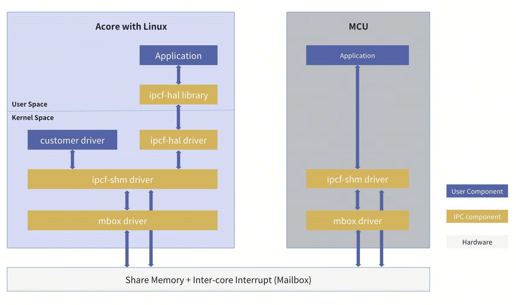
IPCF Software-Hardware Component Block Diagram
Inter-core communication between Acore and MCU primarily uses IPCFHAL on the Acore side and IPCF on the MCU side. IPCFHAL is a wrapper layer based on IPCF, designed to facilitate data transfer between user space and kernel space.
Typical IPC Usage Scenarios
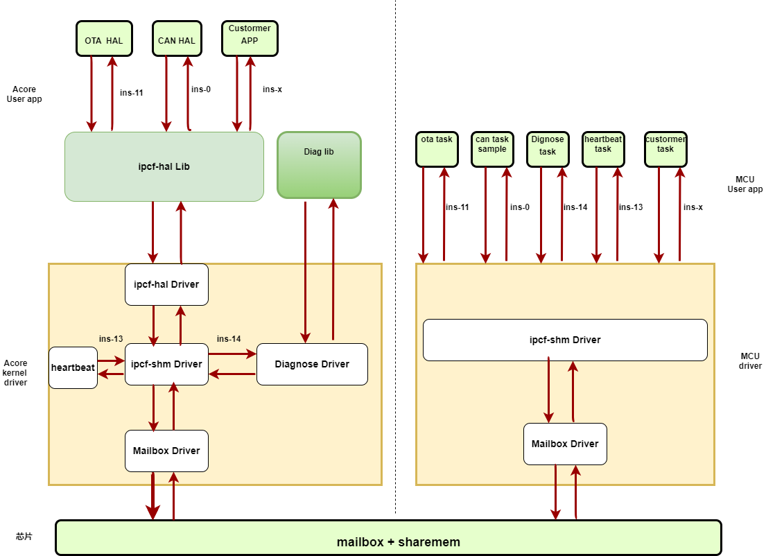
Typical IPC application scenarios include OTA modules, diagnostic modules, planning & control, CANHAL, etc.
IPC Instance Allocation Scheme
On the Acore side, IPC instance IDs range from [0–34], allocated as follows:
- Instances [0–14] for Acore–MCU communication,
- Instances [22–24] for Acore–VDSP communication,
- Instances [32–34] for Acore–BPU communication,
- Remaining instances are reserved for other private purposes.
For Acore–MCU communication, instances [0–8] can be used. By default, instances [4–6] are reserved for customers. If users do not require services like CANHAL or planning & control, they may modify the configuration files accordingly. For details on IPC communication between Acore and MCU in the S100 platform, refer to the "IPC Usage Overview" section in the MCU IPC User Guide.
Method for Configuring Instances on the Acore Side
Instances on the Acore side can be configured via the device tree files, located at:
source/hobot-drivers/kernel-dts/drobot-s100-ipc.dtsi
source/hobot-drivers/kernel-dts/include/drobot_s100_ipc.h
Example device tree configuration (for reference only):
ipcfhal_cfg: ipcfhal_cfg {
    status = "okay"; # Node status, no modification needed
    compatible = "hobot,hobot-ipcfhal";  # Node compatibility property, must not be changed

    /****************instance--num_chans--num_bufs--buf_size****************/
    ipc-ins = <&ipc_instance0	8	8	0x2000>, #(Acore&MCU) for CANHAL
            <&ipc_instance1	8	8	0x1000>, #(Acore&MCU) for planning & control
            <&ipc_instance2	2	8	0x800>, #(Acore&MCU) for planning & control
            <&ipc_instance3	8	8	0x1000>, #(Acore&MCU) for crypto
            <&ipc_instance4	8	8	0x1000>, #(Acore&MCU) free, configurable by user
            <&ipc_instance5	8	8	0x1000>, #(Acore&MCU) free, configurable by user
            <&ipc_instance6	8	8	0x1000>, #(Acore&MCU) free, configurable by user
            <&ipc_instance7	8	8	0x1000>, #(Acore&MCU) for transparent transmission of peripherals such as UART, SPI, I2C, and running MCU-side cmd applications
            <&ipc_instance8	8	8	0x1000>, #(Acore&MCU) partially free, configurable by user
            <&ipc_instance9	2	5	0x400>,  #(Acore&MCU) private instance, internally reserved
            <&ipc_instance10	1	5	0x200>, #(Acore&MCU) private instance, internally reserved
            <&ipc_instance22	8	8	0x1000>, #(Acore&VDSP) reserved for VDSP, not yet open to customers
            <&ipc_instance23	8	8	0x1000>, #(Acore&VDSP) reserved for VDSP, not yet open to customers
            <&ipc_instance24	8	8	0x1000>; #(Acore&VDSP) reserved for VDSP, not yet open to customers
};
Device Tree Configuration Notes
The ipcfhal_cfg node in the device tree includes default configurations for several instances:
- The first column specifies the instance ID, which must be unique and within the valid range.
- The second column defines the number of channels allocated to the instance; users may configure this value, with a maximum of 32 channels.
- The third column indicates the number of buffer buffers per channel; users may configure this value, with a maximum of 1024 buffers, though limited by available control space.
- The fourth column specifies the buffer size in bytes; users may configure this value. The product of (number of channels × number of buffers per channel × buffer size) must be ≤ 0.5 MB (each instance currently pre-allocates 1 MB of data space, which is not expandable).
An example device tree node for a single instance is shown below:
#Not used, User can apply for it
ipc_instance3: ipc_instance3 {
        status = "okay"; # Node status, no modification needed
        compatible = "hobot,hobot-ipc"; # Node compatibility property, must not be changed
        mbox-names = "mbox-chan"; # Mailbox name property, must not be changed
        mboxes = <&mailbox0 3 19 3>; # Mailbox communication direction; only instances 5 and 6 need modification, others remain unchanged
        instance = <3>; # Instance ID, no modification needed
        data_local_addr = /bits/ 64 <IPC_INS3_DATA_LOCAL>; # Acore data segment; only instances 5 and 6 need modification
        data_remote_addr = /bits/ 64 <IPC_INS3_DATA_REMOTE>; # MCU data segment; only instances 5 and 6 need modification
        data_size = <IPC_SINGLE_DATA_SIZE>; # Data segment size, must not be changed (in bytes)
        ctrl_local_addr = /bits/ 64 <IPC_INS3_CTRL_LOCAL>; # Acore control segment; only instances 5 and 6 need modification
        ctrl_remote_addr = /bits/ 64 <IPC_INS3_CTRL_REMOTE>; # MCU control segment; only instances 5 and 6 need modification
        ctrl_size = <IPC_SINGLE_CTRL_SIZE>; # Control segment size, must not be changed (in bytes)
};
Since instances 5 and 6 are internally used for testing, external customers who wish to use them must configure them manually as shown below (no further changes needed):
ipc_instance5: ipc_instance5 {
        status = "okay";
        compatible = "hobot,hobot-ipc";
        mbox-names = "mbox-chan";
        mboxes = <&mailbox0 5 21 5>;
        instance = <5>;
        data_local_addr = /bits/ 64 <IPC_INS5_DATA_LOCAL>;
        data_remote_addr = /bits/ 64 <IPC_INS5_DATA_REMOTE>;
        data_size = <IPC_SINGLE_DATA_SIZE>;
        ctrl_local_addr = /bits/ 64 <IPC_INS5_CTRL_LOCAL>;
        ctrl_remote_addr = /bits/ 64 <IPC_INS5_CTRL_REMOTE>;
        ctrl_size = <IPC_SINGLE_CTRL_SIZE>;
};

ipc_instance6: ipc_instance6 {
        status = "okay";
        compatible = "hobot,hobot-ipc";
        mbox-names = "mbox-chan";
        mboxes = <&mailbox0 6 22 6>;
        instance = <6>;
        data_local_addr = /bits/ 64 <IPC_INS6_DATA_LOCAL>;
        data_remote_addr = /bits/ 64 <IPC_INS6_DATA_REMOTE>;
        data_size = <IPC_SINGLE_DATA_SIZE>;
        ctrl_local_addr = /bits/ 64 <IPC_INS6_CTRL_LOCAL>;
        ctrl_remote_addr = /bits/ 64 <IPC_INS6_CTRL_REMOTE>;
        ctrl_size = <IPC_SINGLE_CTRL_SIZE>;
};
Important Notes for Device Tree Configuration:
- Instances 3–8 have 1 MB of data space pre-allocated by default: 0.5 MB for Acore and 0.5 MB for MCU. Therefore, (number of channels × number of buffers per channel × buffer size) must be ≤ 0.5 MB.
- Instances 3–8 have 5 KB of control space pre-allocated: 2.5 KB for Acore and 2.5 KB for MCU, used to store ring buffer control and status information. Thus, ((number of buffers + 2) × 16 × number of channels + 8) must be ≤ 2.5 KB.
- Instances 5–6 are used internally by D-Robotics for testing; users may adopt the above configuration and modify the device tree nodes accordingly. // TODO: Consider fully opening these to customers.
- The number of channels per instance must be �≤ 32, and the number of buffers per channel must be ≤ 1024, while also satisfying the two constraints above.
- Using different channels within the same instance or using different instances has minimal impact on transmission performance. The main considerations are whether
buf_size/buf_numare appropriate and whether the design facilitates development and maintenance. - Mailbox interrupt allocation at the hardware level is not configurable.
- The number of channels, number of buffers, and buffer size must be identical on both Acore and MCU sides. Additionally, the
localandremoteaddresses for data and control segments must be opposite between the two sides. - The first address of an instance’s control segment stores the initialization status, which can be used to determine whether the instance has been initialized. By default, Acore completes initialization during kernel boot.
- If users need to allocate custom data and address segments, they must modify the Acore device tree file, Uboot device tree file, and MCU configuration file.
- Within the same channel, sending (push) and receiving (pop) operations use independent ring buffers and interrupt mechanisms, ensuring that transmit and receive operations are fully independent and do not interfere with each other.
Usage of User-Space IPC Applications and Configuration Files
The IPC Sample demonstrates bidirectional IPC communication between Acore and MCU, showcasing multi-instance, multi-channel, and multi-threaded usage of IPC.
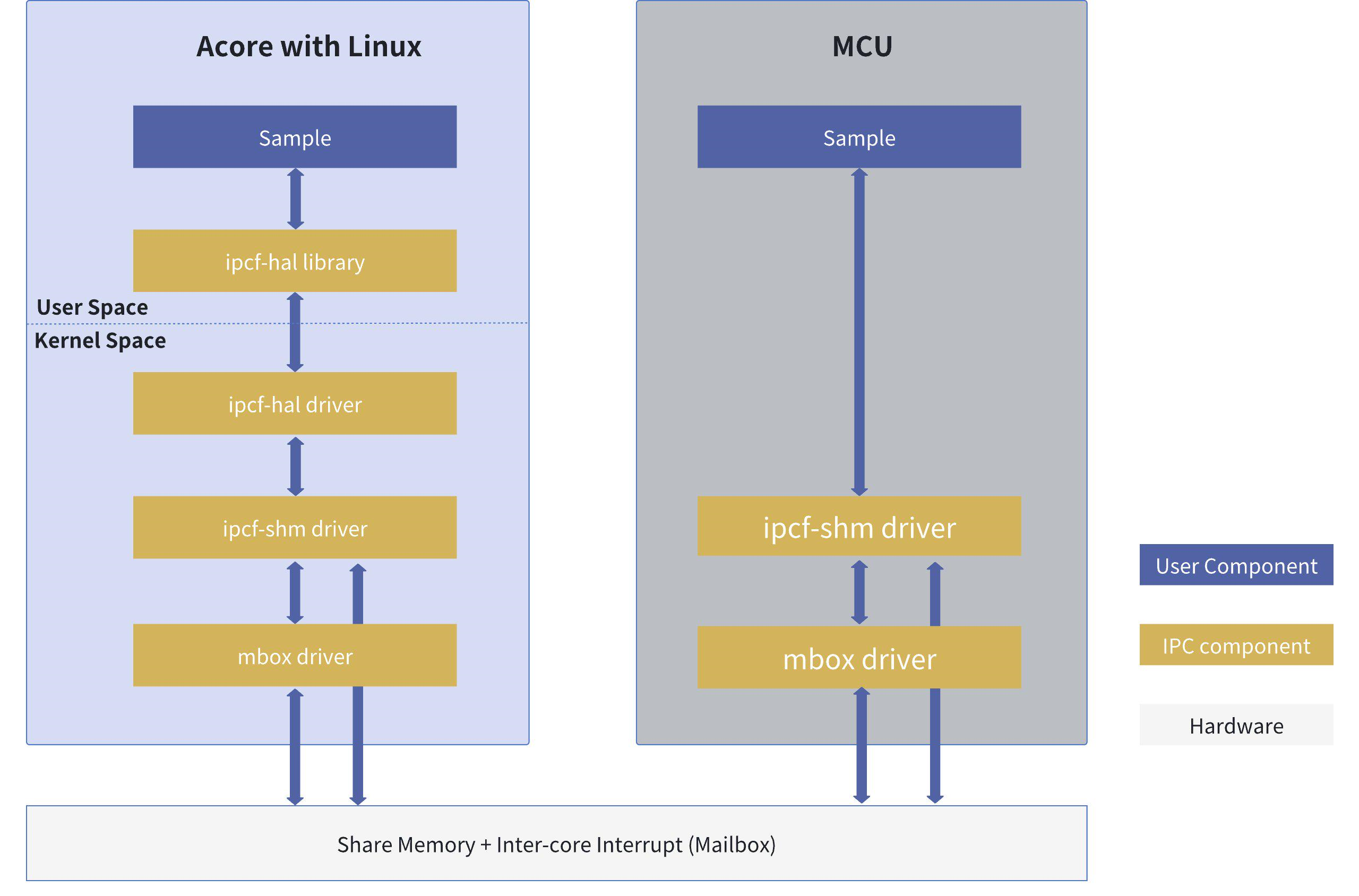
In the Sample software architecture diagram, Acore uses the libipcfhal interface for data transmission and reception, with the underlying implementation based on the IPCF driver. MCU directly uses the IPCF interface for communication. Since Acore provides multiple IPC interfaces for clarity, they are referred to as IPCFHAL, RPMSG, and IPCF respectively. MCU, however, has only one IPC interface, so IPCF is uniformly referred to as IPC in MCU-side documentation.
Hardware Data Flow Description
Shared memory data flow and interrupt signal flow in the Sample
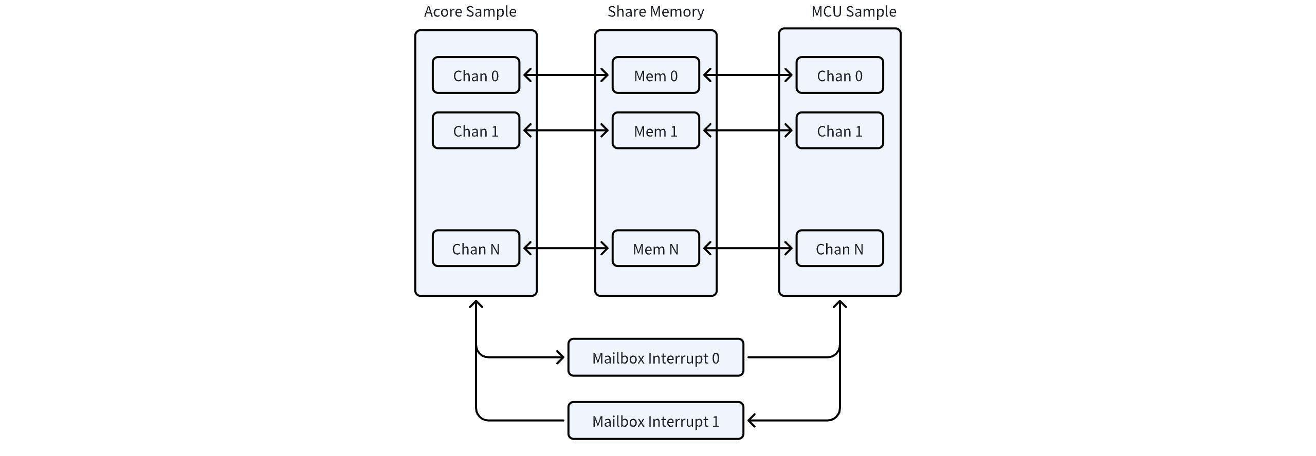
In the Sample, Acore and MCU exchange data via shared memory and notify each other through mailbox interrupts.
Sample Code Location and Directory Structure on the Acore Side
Code Paths:
# Sample source code paths
${SDK}/source/hobot-io-samples/debian/app/ipcbox_sample  # IPC C++ Sample
${SDK}/source/hobot-io-samples/debian/app/pyhbipchal_sample # IPC Python Sample
${SDK}/source/hobot-io/debian/app/pyhbipchal # Source code for converting the IPC C++ library into a Python library


# Source code is packaged with firmware and can be compiled directly on S100 at the following paths:
${S100}/app/ipcbox_sample
${S100}/app/pyhbipchal_sample
Directory Structure:
root@ubuntu:/app/ipcbox_sample# tree .
.
├── ipcbox_runcmd # Sample for running MCU-side cmd commands
│   ├── Makefile # Sample build framework
│   ├── ipcbox_runcmd.cpp # Sample source code
│   └── ipcfhal_sample_config.json # Sample configuration file
└── ipcbox_uart # IPC UART transparent transmission Sample
    ├── Makefile # Sample build framework
    ├── ipcbox_uart.cpp # Sample source code
    └── ipcfhal_sample_config.json # Sample configuration file
IPC Real-Time Performance Optimization Settings
If real-time performance of IPC communication needs to be improved in specific scenarios, follow the steps below, using ipc_instance5 as an example.
- First, locate the interrupt number and interrupt thread PID corresponding to ipc_instance5
# Find interrupt number:
root@ubuntu:~# cat /proc/interrupts | grep "mailbox"
 14:          0          0          0          0          0          0     GICv3 293 Level     29f00000.mailbox0
 15:          0          0          0          0          0          0     GICv3 294 Level     29f00000.mailbox0
 16:          0          0          0          0          0          0     GICv3 295 Level     29f00000.mailbox0
 17:          0          0          0          0          0          0     GICv3 296 Level     29f00000.mailbox0
 18:          0          0          0          0          0          0     GICv3 297 Level     29f00000.mailbox0
 19:          0          0          0          0          0          0     GICv3 298 Level     29f00000.mailbox0
 20:          0          0          0          0          0          0     GICv3 299 Level     29f00000.mailbox0
 21:          0          0          0          0          0          0     GICv3 300 Level     29f00000.mailbox0
 22:          0          0          0          0          0          0     GICv3 301 Level     29f00000.mailbox0
 23:          0          0          0          0          0          0     GICv3 302 Level     29f00000.mailbox0
 24:          0          0          0          0          0          0     GICv3 303 Level     29f00000.mailbox0
 25:          1          0          1          0          1          1     GICv3 304 Level     29f00000.mailbox0
 26:          0          0          0          0          0          0     GICv3 305 Level     29f00000.mailbox0
 27:          0          0          0          0          0          0     GICv3 306 Level     29f00000.mailbox0
 28:          0          0          0          0          0          0     GICv3 307 Level     29f00000.mailbox0
 29:          0          0          0          0          0          0     GICv3 280 Level     29f01000.mailbox1
 30:          0          0          0          0          0          0     GICv3 281 Level     29f01000.mailbox1
 31:          0          0          0          0          0          0     GICv3 282 Level     29f01000.mailbox1
 32:          0          0          0          0          0          0     GICv3 283 Level     29f01000.mailbox1
 33:          0          0          0          0          0          0     GICv3 284 Level     29f01000.mailbox1
 34:          0          0          0          0          0          0     GICv3 285 Level     29f01000.mailbox1
 35:          0          0          0          0          0          0     GICv3 286 Level     29f01000.mailbox1
 36:          0          0          0          0          0          0     GICv3 287 Level     29f01000.mailbox1
 37:          0          0          0          0          0          0     GICv3 288 Level     29f01000.mailbox1
 38:          0          0          0          0          0          0     GICv3 289 Level     29f01000.mailbox1
 39:          0          0          0          0          0          0     GICv3 290 Level     29f01000.mailbox1
 40:          0          0          0          0          0          0     GICv3 291 Level     29f01000.mailbox1
 41:          0          0          0          0          0          0     GICv3 292 Level     29f01000.mailbox1
 42:          0          0          0          0          0          0     GICv3  50 Level     28109000.mailbox2
 43:          0          0          0          0          0          0     GICv3  52 Level     2810d000.mailbox3
 44:          0          0          0          0          0          0     GICv3  54 Level     28105000.mailbox4
# Find interrupt thread PID:
root@ubuntu:~# ps aux | grep "mailbox"
root          70  0.0  0.0      0     0 ?        S    22:17   0:00 [irq/14-29f00000.mailbox0]
root          71  0.0  0.0      0     0 ?        S    22:17   0:00 [irq/15-29f00000.mailbox0]
root          72  0.0  0.0      0     0 ?        S    22:17   0:00 [irq/16-29f00000.mailbox0]
root          73  0.0  0.0      0     0 ?        S    22:17   0:00 [irq/17-29f00000.mailbox0]
root          74  0.0  0.0      0     0 ?        S    22:17   0:00 [irq/18-29f00000.mailbox0]
root          75  0.0  0.0      0     0 ?        S    22:17   0:00 [irq/19-29f00000.mailbox0]
root          76  0.0  0.0      0     0 ?        S    22:17   0:00 [irq/20-29f00000.mailbox0]
root          77  0.0  0.0      0     0 ?        S    22:17   0:00 [irq/21-29f00000.mailbox0]
root          78  0.0  0.0      0     0 ?        S    22:17   0:00 [irq/22-29f00000.mailbox0]
root          79  0.0  0.0      0     0 ?        S    22:17   0:00 [irq/23-29f00000.mailbox0]
root          80  0.0  0.0      0     0 ?        S    22:17   0:00 [irq/24-29f00000.mailbox0]
root          81  0.0  0.0      0     0 ?        S    22:17   0:00 [irq/25-29f00000.mailbox0]
root          82  0.0  0.0      0     0 ?        S    22:17   0:00 [irq/26-29f00000.mailbox0]
root          83  0.0  0.0      0     0 ?        S    22:17   0:00 [irq/27-29f00000.mailbox0]
root          84  0.0  0.0      0     0 ?        S    22:17   0:00 [irq/28-29f00000.mailbox0]
root          85  0.0  0.0      0     0 ?        S    22:17   0:00 [irq/29-29f01000.mailbox1]
root          86  0.0  0.0      0     0 ?        S    22:17   0:00 [irq/30-29f01000.mailbox1]
root          87  0.0  0.0      0     0 ?        S    22:17   0:00 [irq/31-29f01000.mailbox1]
root          88  0.0  0.0      0     0 ?        S    22:17   0:00 [irq/32-29f01000.mailbox1]
root          89  0.0  0.0      0     0 ?        S    22:17   0:00 [irq/33-29f01000.mailbox1]
root          90  0.0  0.0      0     0 ?        S    22:17   0:00 [irq/34-29f01000.mailbox1]
root          91  0.0  0.0      0     0 ?        S    22:17   0:00 [irq/35-29f01000.mailbox1]
root          92  0.0  0.0      0     0 ?        S    22:17   0:00 [irq/36-29f01000.mailbox1]
root          93  0.0  0.0      0     0 ?        S    22:17   0:00 [irq/37-29f01000.mailbox1]
root          94  0.0  0.0      0     0 ?        S    22:17   0:00 [irq/38-29f01000.mailbox1]
root          95  0.0  0.0      0     0 ?        S    22:17   0:00 [irq/39-29f01000.mailbox1]
root          96  0.0  0.0      0     0 ?        S    22:17   0:00 [irq/40-29f01000.mailbox1]
root          97  0.0  0.0      0     0 ?        S    22:17   0:00 [irq/41-29f01000.mailbox1]
root          98  0.0  0.0      0     0 ?        S    22:17   0:00 [irq/42-28109000.mailbox2]
root          99  0.0  0.0      0     0 ?        S    22:17   0:00 [irq/43-2810d000.mailbox3]
root         100  0.0  0.0      0     0 ?        S    22:17   0:00 [irq/44-28105000.mailbox4]
# According to the device tree, ipc_instance5 corresponds to mailbox with mboxes = <&mailbox0 5 21 5>; therefore, the interrupt number is 19, and the interrupt thread PID is 75.
- Bind interrupt to CPU cores to reduce migration overhead
# Bind IRQ 19 to CPU2:
root@ubuntu:/# echo 4 > /proc/irq/19/smp_affinity
- Bind interrupt thread to CPU cores to reduce migration overhead
# Bind PID 75 to CPU2:
root@ubuntu:/# taskset -p 0x04 75
pid 75's current affinity mask: 3f
pid 75's new affinity mask: 4
- Set interrupt thread priority to prevent interruption by high-priority tasks
# Increase PID 75's priority to 99
root@ubuntu:/# chrt -f -p 99 75
root@ubuntu:/# chrt -p 75
pid 75's current scheduling policy: SCHED_FIFO
pid 75's current scheduling priority: 99
- Isolate interrupt CPU cores to ensure dedicated CPU for real-time tasks
# Isolate CPU2 by configuring in uboot mode
Hobot$ printenv bootargs
bootargs=earlycon=uart8250,mmio32,0x394B0000 no_console_suspend root=/dev/ram0 rdinit=/init rootwait net.ifnames=0
Hobot$ setenv bootargs "${bootargs} isolcpus=2 nohz_full=2 rcu_nocbs=2"
Hobot$ saveenv
Saving Environment to MMC... Writing to MMC(0)... OK
Hobot$ reset
# Verify after system startup
root@ubuntu:/# cat /sys/devices/system/cpu/isolated
2
- Configure RT kernel scheduler status to prevent RT tasks from being forcibly yielded
root@ubuntu:/# echo -1 > /proc/sys/kernel/sched_rt_runtime_us
This setting allows all RT tasks to occupy CPU without limitation, thereby improving system real-time performance. However, it may also cause regular tasks to be starved as they cannot obtain scheduling opportunities. Therefore, use -1 with caution. For debugging RT thread scheduling, please refer to the kernel official documentation
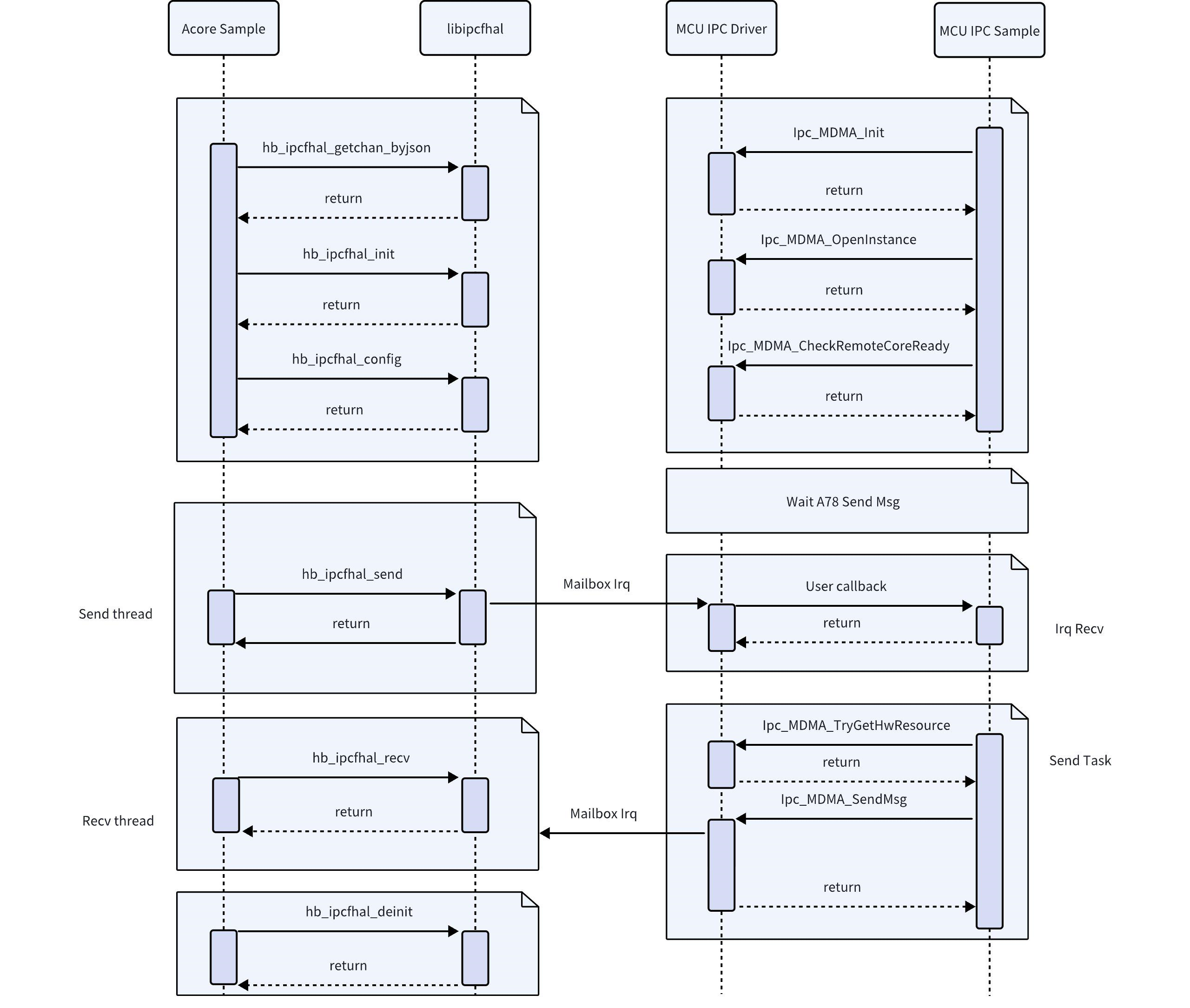
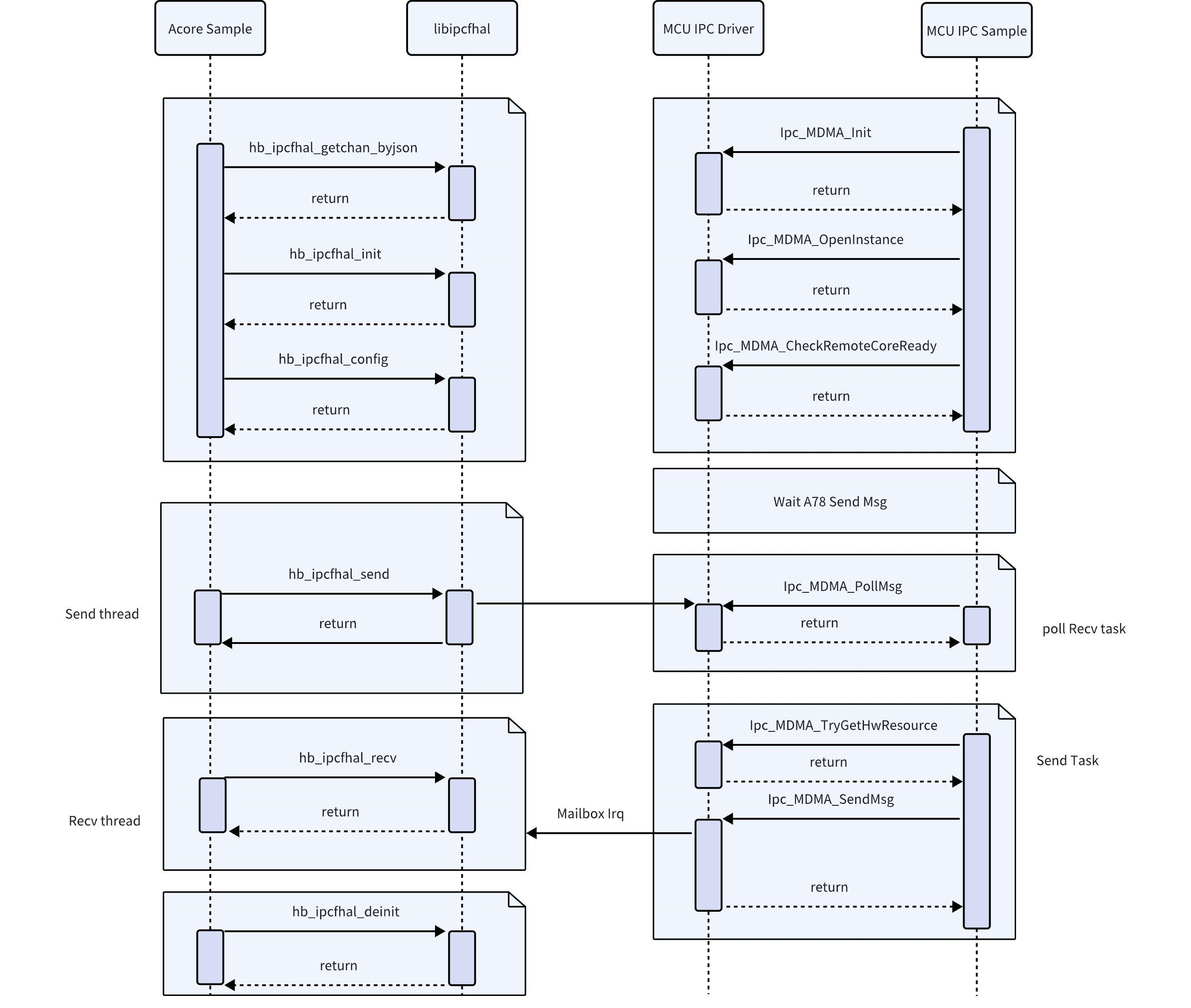
API Workflow Description
API Sample workflow diagram for Acore–MCU communication (IRQ mode)
API Sample workflow diagram for Acore–MCU communication (POLL mode)
Channel Configuration
The number of channels (config_num) can be increased in the JSON file, along with corresponding channel information. This Sample does not support dynamic channel addition; to add channels, users must modify configuration files on both Acore and MCU sides.
{
        "log_level": 0, # Log level (optional)
        "config_num": 4, # Number of configured channels
        "config_num_max":256, # Maximum number of configurable channels
        "config_0": { # Configuration channel
                "name": "cpu2mcu_ins7ch0", # Channel name
                "instance": 7, # Instance ID
                "channel": 0, # Channel ID
                "pkg_size_max": 4096, # Maximum packet size in bytes; recommended to be ≤ 4096 bytes
                "fifo_size": 64000, # FIFO buffer size, determined by the number of items to be buffered
                "fifo_type": 0, # FIFO buffer type; only type 0 is supported
                "ipcf_dev_path":"/dev/ipcdrv", # Character device driver; only "/dev/ipcdrv" is supported
                "ipcf_dev_name":"ipcdrv" # Character device driver name; only "ipcdrv" is supported
        },
        "config_1": {
                "name": "cpu2mcu_ins7ch1",
                "instance": 7,
                "channel": 1,
                "pkg_size_max": 4096,
                "fifo_size": 64000,
                "fifo_type": 0,
                "ipcf_dev_path":"/dev/ipcdrv",
                "ipcf_dev_name":"ipcdrv"
        },
        "config_2": {
                "name": "cpu2mcu_ins8ch0",
                "instance": 8,
                "channel": 0,
                "pkg_size_max": 4096,
                "fifo_size": 64000,
                "fifo_type": 0,
                "ipcf_dev_path":"/dev/ipcdrv",
                "ipcf_dev_name":"ipcdrv"
        },
        "config_3": {
                "name": "cpu2mcu_ins8ch1",
                "instance": 8,
                "channel": 1,
                "pkg_size_max": 4096,
                "fifo_size": 64000,
                "fifo_type": 0,
                "ipcf_dev_path":"/dev/ipcdrv",
                "ipcf_dev_name":"ipcdrv"
        }
}
Instance Description
Error Code Definitions
| Error Code Macro | Error Code Value | Description |
|---|---|---|
IPCF_HAL_E_OK | 0 | Operation succeeded |
IPCF_HAL_E_NOK | 1 | Operation failed |
IPCF_HAL_E_CONFIG_FAIL | 2 | Configuration failed |
IPCF_HAL_E_WRONG_CONFIGURATION | 3 | Invalid configuration |
IPCF_HAL_E_NULL_POINTER | 4 | Null pointer passed as argument |
IPCF_HAL_E_PARAM_INVALID | 5 | Invalid parameter |
IPCF_HAL_E_LENGTH_TOO_SMALL | 6 | Length too small |
IPCF_HAL_E_INIT_FAILED | 7 | Initialization failed |
IPCF_HAL_E_UNINIT | 8 | Called before initialization |
IPCF_HAL_E_BUFFER_OVERFLOW | 9 | Buffer overflow at source or destination address |
IPCF_HAL_E_ALLOC_FAIL | 10 | Resource allocation failed |
IPCF_HAL_E_TIMEOUT | 11 | Operation timed out |
IPCF_HAL_E_REINIT | 12 | Re-initialization attempted |
IPCF_HAL_E_BUSY | 13 | System busy |
IPCF_HAL_E_CHANNEL_INVALID | 14 | Data write channel status abnormal: kernel-space RingBuffer has reached its capacity limit, causing the write operation to fail. It is recommended to wait 1–2 ms and retry the operation. Data read channel status abnormal: kernel-space RingBuffer is empty, causing the read operation to fail. It is recommended to wait 1–2 ms and retry the operation. |
C++ Application
The Acore side implements multiple applications for operating the peripherals on the MCU side. These applications are located in the /app/ipcbox_sample directory:
root@ubuntu:/app/ipcbox_sample# tree -L 1
.
├── common                # Common files, implementing data packetization, unpacking, data validation, etc.
├── ipcbox_i2c             # Sample for operating the I2C peripheral on the MCU side
├── ipcbox_runcmd          # Sample for running cmd commands on the MCU side
├── ipcbox_spi             # Sample for operating the SPI peripheral on the MCU side
└── ipcbox_uart            # Sample for operating the UART peripheral on the MCU side
- These applications actually operate the peripherals on the MCU side. Before using them, please ensure that MCU1 is started. For information on starting MCU1, please refer to MCU1 Startup
- When operating these peripherals, you need to confirm whether the MCU side has configured these peripherals for passthrough. Please refer to MCU Side IPCBOX Configuration
RunCmd Application
This sample implements reading the voltage from an ADC channel.
- After booting into S100, navigate to the application directory:
/app/ipcbox_sample/ipcbox_runcmd - Compile:
make - Run:
./ipcbox_runcmd - If the log message
Extracted adc data:{"adc_ch":1,"adc_result":2411,"adc_mv":1059}appears, the test passes.
Here, adc_ch indicates the corresponding ADC pin, and adc_mv represents the measured voltage value.
root@ubuntu:/app/ipcbox_sample/ipcbox_runcmd# ./ipcbox_runcmd
[INFO][hb_ipcf_hal.cpp:282] [channel] cpu2mcu_ins7ch0 [ins] 7 [id] 0 init success.
[INFO][hb_ipcf_hal.cpp:333] [channel] cpu2mcu_ins7ch0 [ins] 7 [id] 0 config success.
[INFO][hb_ipcf_hal.cpp:282] [channel] cpu2mcu_ins7ch1 [ins] 7 [id] 1 init success.
[INFO][hb_ipcf_hal.cpp:333] [channel] cpu2mcu_ins7ch1 [ins] 7 [id] 1 config success.
Extracted adc data:{"adc_ch":1,"adc_result":2411,"adc_mv":1059}
TxCmdItem(96)
44 2D 49 50 43 42 4F 58 01 00 00 00 55 07 00 00
69 70 63 73 65 6E 64 5F 61 64 63 20 31 00 00 00
00 00 00 00 00 00 00 00 00 00 00 00 00 00 00 00
00 00 00 00 00 00 00 00 00 00 00 00 00 00 00 00
00 00 00 00 00 00 00 00 00 00 00 00 00 00 00 00
60 00 00 00 00 00 00 00 00 00 00 00 00 00 00 00

rx_packet(160):D-IPCBOX
44 2D 49 50 43 42 4F 58 01 00 00 00 4B 10 00 00
00 00 00 00 00 00 00 00 00 00 00 00 00 00 00 00
00 00 00 00 00 00 00 00 00 00 00 00 00 00 00 00
00 00 00 00 00 00 00 00 00 00 00 00 00 00 00 00
00 00 00 00 00 00 00 00 00 00 00 00 00 00 00 00
A0 00 00 00 00 00 00 00 00 00 00 00 00 00 00 00
7B 22 61 64 63 5F 63 68 22 3A 31 2C 22 61 64 63
5F 72 65 73 75 6C 74 22 3A 32 34 31 31 2C 22 61
64 63 5F 6D 76 22 3A 31 30 35 39 7D 00 00 00 00
00 00 00 00 00 00 00 00 00 00 00 00 00 00 00 00
00 C9 F5 5A 58 13 C3 E8 F0 1C E7 DE FF FF 00 00
CC 74 22 8A FF FF 00 00 74 47 67 8A FF FF 00 00
A4 0F 1F D4 AA AA 00 00 06 00 00 00 01 00 00 00
58 1D E7 DE FF FF 00 00 58 1D E7 DE FF FF 00 00
01 00 00 00 00 00 00 00 D8 1C 20 D4 AA AA 00 00
40 C0 69 8A FF FF 00 00 A4 0F 1F D4 AA AA 00 00

[INFO][hb_ipcf_hal.cpp:553] [channel] cpu2mcu_ins7ch0 [ins] 7 [id] 0 deinit success.
[INFO][hb_ipcf_hal.cpp:553] [channel] cpu2mcu_ins7ch1 [ins] 7 [id] 1 deinit success.
SPI Read/Write Test
This sample implements a loopback test for SPI. During the test, the MOSI and MISO pins of SPI3 need to be shorted together.
- After booting and entering S100, open the application directory:
cd /app/ipcbox_sample/ipcbox_spi - Compile:
make - Run:
./ipcbox_spi - The test passes when you see the log message
SPI write successful, 128 bytes. Reference log output:root@ubuntu:/app/ipcbox_sample/ipcbox_spi# ./ipcbox_spi -b 3
[INFO][hb_ipcf_hal.cpp:282] [channel] cpu2mcu_ins7ch2 [ins] 7 [id] 2 init success.
[INFO][hb_ipcf_hal.cpp:333] [channel] cpu2mcu_ins7ch2 [ins] 7 [id] 2 config success.
SPI write successful, 128 bytes
tx_data(128)
00 01 02 03 04 05 06 07 08 09 0A 0B 0C 0D 0E 0F
10 11 12 13 14 15 16 17 18 19 1A 1B 1C 1D 1E 1F
20 21 22 23 24 25 26 27 28 29 2A 2B 2C 2D 2E 2F
30 31 32 33 34 35 36 37 38 39 3A 3B 3C 3D 3E 3F
40 41 42 43 44 45 46 47 48 49 4A 4B 4C 4D 4E 4F
50 51 52 53 54 55 56 57 58 59 5A 5B 5C 5D 5E 5F
60 61 62 63 64 65 66 67 68 69 6A 6B 6C 6D 6E 6F
70 71 72 73 74 75 76 77 78 79 7A 7B 7C 7D 7E 7F
rx_packet(128)
00 01 02 03 04 05 06 07 08 09 0A 0B 0C 0D 0E 0F
10 11 12 13 14 15 16 17 18 19 1A 1B 1C 1D 1E 1F
20 21 22 23 24 25 26 27 28 29 2A 2B 2C 2D 2E 2F
30 31 32 33 34 35 36 37 38 39 3A 3B 3C 3D 3E 3F
40 41 42 43 44 45 46 47 48 49 4A 4B 4C 4D 4E 4F
50 51 52 53 54 55 56 57 58 59 5A 5B 5C 5D 5E 5F
60 61 62 63 64 65 66 67 68 69 6A 6B 6C 6D 6E 6F
70 71 72 73 74 75 76 77 78 79 7A 7B 7C 7D 7E 7F
[INFO][hb_ipcf_hal.cpp:553] [channel] cpu2mcu_ins7ch2 [ins] 7 [id] 2 deinit success.
IpcBox only implements control for SPI Master, with the following limitations:
- Slave mode is not supported
- The MCU side底层 defaults to interrupt + asynchronous mode, with synchronous mode supported
- Application layer control of frame length is not supported
UART Passthrough
Test Prerequisites
Before testing, you need to short-circuit the TX and RX of the Uart to be used. The default Uart used by S100 is as follows:
| Platform | Uart id |
|---|---|
| S100 | Uart5 |
The test sample implements transparent transmission of Uart. The operation steps are as follows:
- After booting into S100, navigate to the application directory:
cd /app/ipcbox_sample/ipcbox_uart - Compile:
make - Run:
./ipcbox_uart - If the message
tx_data and rx_data are identical.appears, the test passes. Sample log output is as follows:
# ./ipcbox_uart
[INFO][hb_ipcf_hal.cpp:282] [channel] cpu2mcu_ins7ch4 [ins] 7 [id] 4 init success.
[INFO][hb_ipcf_hal.cpp:333] [channel] cpu2mcu_ins7ch4 [ins] 7 [id] 4 config success.
tx_data(64)
69 70 63 5F 72 75 6E 63 6D 64 5F 73 65 6E 64 20
37 20 30 20 31 32 33 34 35 36 37 38 39 20 31 30
00 00 00 00 00 00 00 00 00 00 00 00 00 00 00 00
00 00 00 00 00 00 00 00 00 00 00 00 00 00 00 00

rx_data(64)
69 70 63 5F 72 75 6E 63 6D 64 5F 73 65 6E 64 20
37 20 30 20 31 32 33 34 35 36 37 38 39 20 31 30
00 00 00 00 00 00 00 00 00 00 00 00 00 00 00 00
00 00 00 00 00 00 00 00 00 00 00 00 00 00 00 00

tx_data and rx_data are identical.
[INFO][hb_ipcf_hal.cpp:553] [channel] cpu2mcu_ins7ch4 [ins] 7 [id] 4 deinit success.
Python Application
Test Prerequisites
Since the Python application calls the Uart in IpcBox, similar to the C++ use cases, the TX and RX of the Uart need to be shorted before testing. The default Uart used by S100 is as follows:
| Platform | Uart id |
|---|---|
| S100 | Uart5 |
- The application actually operates on the MCU-side peripherals. Before use, confirm whether MCU1 has started. For MCU1 startup, please refer to MCU1 Startup
- When operating these peripherals, you need to confirm whether the MCU side has configured them for transparent transmission. For reference, see MCU-side IPCBOX Configuration
S100 provides Python library files for using Ipc. The principle is to call the C++ interface through pybind11, with function names and macro definitions remaining consistent on both ends.
- Importing packages
import pyhbipchal as pyipc
import pyhbipchal_utils as ipc_utils
from ipcbox_packet import ipcbox_packet
- Source code directory structure
├── ipcbox_packet.py // Encapsulation of ipcbox_packet object
├── ipcfhal_sample_config.json // Configuration file used for IPC initialization
├── pyhbipchal_test.py // Basic Python application test case using the pyhbipchal library
├── pyhbipchal_utils.py // Source code of pyhbipchal_utils, which provides a Pythonic wrapper over pyhbipchal
└── pyhbipchal_utils_test.py // Test cases for pyhbipchal_utils
- Example
Testing whether the Python library behaves consistently with the C++ interfaces:
root@ubuntu:/app/pyhbipchal_sample# python pyhbipchal_test.py
Library version: 1.0.0
====================test error code==================

IPCF_HAL_E_OK (0): General OK

IPCF_HAL_E_NOK (-1): General Not OK

IPCF_HAL_E_CONFIG_FAIL (-2): Config fail

IPCF_HAL_E_WRONG_CONFIGURATION (-3): Wrong configuration

IPCF_HAL_E_NULL_POINTER (-4): A null pointer was passed as an argument

IPCF_HAL_E_PARAM_INVALID (-5): A parameter was invalid

IPCF_HAL_E_LENGTH_TOO_SMALL (-6): Length too small

IPCF_HAL_E_INIT_FAILED (-7): Initialization failed

IPCF_HAL_E_UNINIT (-8): Called before initialization

IPCF_HAL_E_BUFFER_OVERFLOW (-9): Source address or destination address Buffer overflow

IPCF_HAL_E_ALLOC_FAIL (-10): Source alloc fail

IPCF_HAL_E_TIMEOUT (-11): Expired the time out

IPCF_HAL_E_REINIT (-12): Re initilize

IPCF_HAL_E_BUSY (-13): Busy

IPCF_HAL_E_CHANNEL_INVALID (-14): Channel is invalid

=====================test OK=======================

[INFO][hb_ipcf_hal.cpp:282] [channel] cpu2mcu_ins7ch1 [ins] 7 [id] 1 init success.
[INFO][hb_ipcf_hal.cpp:333] [channel] cpu2mcu_ins7ch1 [ins] 7 [id] 1 config success.
=== Sending Packet ===
Original message: This is the PYIPC UART test
Original data length: 27 bytes
Fixed data length: 32 bytes
Fixed data content (hex):
54 68 69 73 20 69 73 20 74 68 65 20 50 59 49 50
43 20 55 41 52 54 20 74 65 73 74 00 00 00 00 00

IPCBox packet length: 160
Full packet content (hex):
44 49 50 43 01 00 00 00 97 0A 00 00 A0 00 00 00
00 00 00 00 00 00 00 00 00 00 00 00 00 00 00 00
00 00 00 00 00 00 00 00 00 00 00 00 00 00 00 00
00 00 00 00 00 00 00 00 00 00 00 00 00 00 00 00
00 00 00 00 00 00 00 00 00 00 00 00 00 00 00 00
00 00 00 00 00 00 00 00 00 00 00 00 00 00 00 00
00 00 00 00 00 00 00 00 00 00 00 00 00 00 00 00
00 00 00 00 00 00 00 00 00 00 00 00 00 00 00 00
54 68 69 73 20 69 73 20 74 68 65 20 50 59 49 50
43 20 55 41 52 54 20 74 65 73 74 00 00 00 00 00

=== Received Packet ===
Raw received data length: 160
Raw received data (hex):
44 49 50 43 01 00 00 00 97 0A 00 00 A0 00 00 00
00 00 00 00 00 00 00 00 00 00 00 00 00 00 00 00
00 00 00 00 00 00 00 00 00 00 00 00 00 00 00 00
00 00 00 00 00 00 00 00 00 00 00 00 00 00 00 00
00 00 00 00 00 00 00 00 00 00 00 00 00 00 00 00
00 00 00 00 00 00 00 00 00 00 00 00 00 00 00 00
00 00 00 00 00 00 00 00 00 00 00 00 00 00 00 00
00 00 00 00 00 00 00 00 00 00 00 00 00 00 00 00
54 68 69 73 20 69 73 20 74 68 65 20 50 59 49 50
43 20 55 41 52 54 20 74 65 73 74 00 00 00 00 00

tx_data(32)
54 68 69 73 20 69 73 20 74 68 65 20 50 59 49 50
43 20 55 41 52 54 20 74 65 73 74 00 00 00 00 00

rx_data(32)
54 68 69 73 20 69 73 20 74 68 65 20 50 59 49 50
43 20 55 41 52 54 20 74 65 73 74 00 00 00 00 00

[SUCCESS]: tx_data and rx_data are identical.
[INFO][hb_ipcf_hal.cpp:553] [channel] cpu2mcu_ins7ch1 [ins] 7 [id] 1 deinit success.
Test whether the IPC communication functionality of the pyhbipchal_utils package works properly.
root@ubuntu:/app/pyhbipchal_sample# python pyhbipchal_utils_test.py
root@ubuntu:/app/pyhbipchal_sample# python pyhbipchal_utils_test.py
[INFO][hb_ipcf_hal.cpp:282] [channel] cpu2mcu_ins7ch1 [ins] 7 [id] 1 init success.
[INFO][hb_ipcf_hal.cpp:333] [channel] cpu2mcu_ins7ch1 [ins] 7 [id] 1 config success.
Sending IPCBox packet:
Original message: ipc_runcmd_send 7 0 123456789 10
Fixed data length: 32 bytes
IPCBox packet length: 160 bytes
IPCBox packet content (hex):
44 49 50 43 01 00 00 00 13 0B 00 00 A0 00 00 00
00 00 00 00 00 00 00 00 00 00 00 00 00 00 00 00
00 00 00 00 00 00 00 00 00 00 00 00 00 00 00 00
00 00 00 00 00 00 00 00 00 00 00 00 00 00 00 00
00 00 00 00 00 00 00 00 00 00 00 00 00 00 00 00
00 00 00 00 00 00 00 00 00 00 00 00 00 00 00 00
00 00 00 00 00 00 00 00 00 00 00 00 00 00 00 00
00 00 00 00 00 00 00 00 00 00 00 00 00 00 00 00
69 70 63 5F 72 75 6E 63 6D 64 5F 73 65 6E 64 20
37 20 30 20 31 32 33 34 35 36 37 38 39 20 31 30

Received data (hex):
44 49 50 43 01 00 00 00 13 0B 00 00 A0 00 00 00
00 00 00 00 00 00 00 00 00 00 00 00 00 00 00 00
00 00 00 00 00 00 00 00 00 00 00 00 00 00 00 00
00 00 00 00 00 00 00 00 00 00 00 00 00 00 00 00
00 00 00 00 00 00 00 00 00 00 00 00 00 00 00 00
00 00 00 00 00 00 00 00 00 00 00 00 00 00 00 00
00 00 00 00 00 00 00 00 00 00 00 00 00 00 00 00
00 00 00 00 00 00 00 00 00 00 00 00 00 00 00 00
69 70 63 5F 72 75 6E 63 6D 64 5F 73 65 6E 64 20
37 20 30 20 31 32 33 34 35 36 37 38 39 20 31 30

Extracted data length: 32 bytes
Extracted data content (hex):
69 70 63 5F 72 75 6E 63 6D 64 5F 73 65 6E 64 20
37 20 30 20 31 32 33 34 35 36 37 38 39 20 31 30
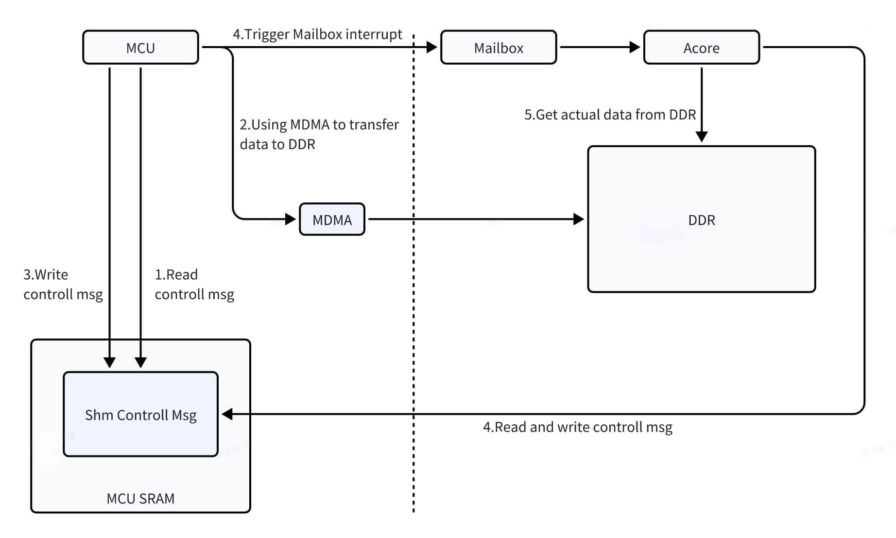
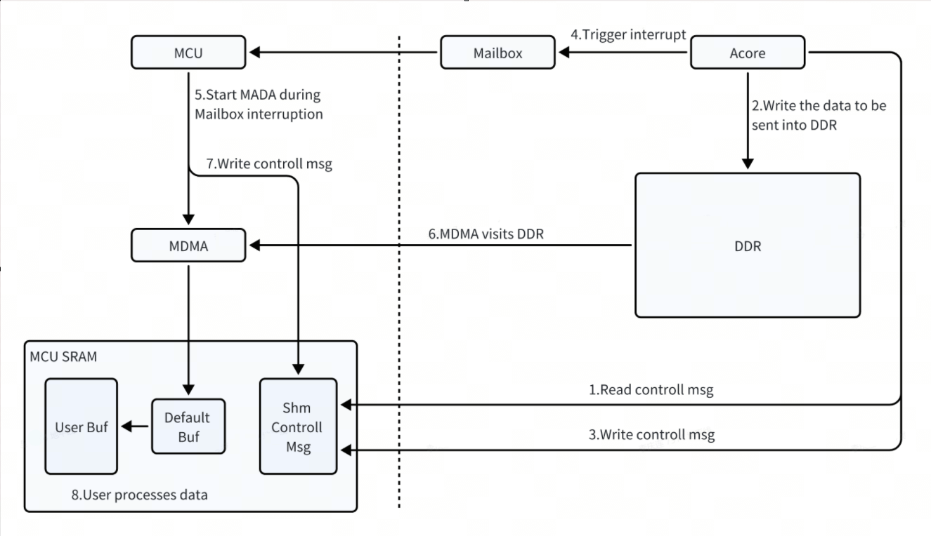
Data Transfer Flow Between Acore and MCU
Acore and MCU IPC communication uses MCU MDMA to transfer data between DDR and MCU SRAM. In the process where the MCU sends data to Acore, the MCU first uses MDMA to move data from SRAM to DDR, then sends an interrupt notification. In the process where Acore sends data to the MCU, upon receiving the interrupt notification, the MCU uses MDMA to move data from DDR to SRAM.
MCU Sending Data to Acore
Acore Sending Data to MCU
IPCFHAL API Usage Sequence
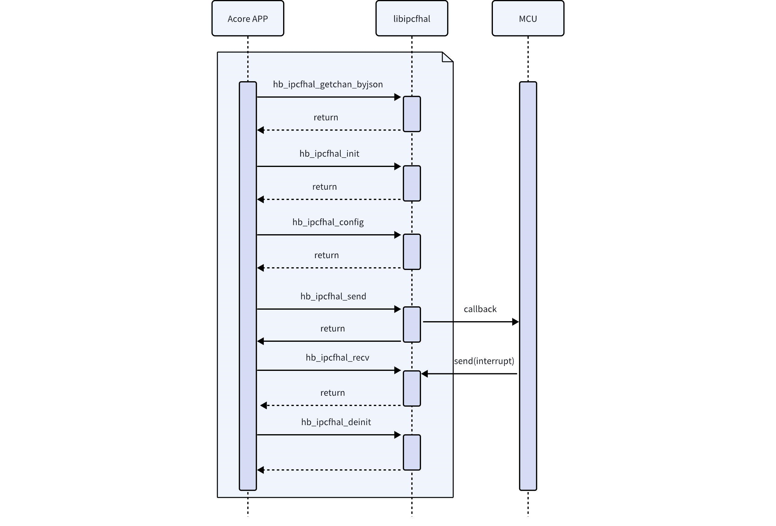
During Acore–MCU communication, IPCFHAL uses the IPCF interface on the MCU side.
IPCFHAL Usage Notes
- IPCFHAL does not support multiple processes on the same channel; if multi-threaded transmission/reception is used, the user must ensure proper sequencing and logic.
- The MCU-side SRAM FIFO is too small and intended only for internal use. To conserve SRAM, customers may opt to use a DDR-based solution.
- Interrupt priorities for each instance on the Acore side are not configurable, whereas they are configurable on the MCU side.
- If the application is sensitive to fluctuations in system scheduling latency, the application’s scheduling policy can be adjusted to SCHED_FIFO.
IPCFHAL Debugging Methods
Debug Logs
IPCFHAL, along with the underlying IPCF and Mailbox drivers, provides comprehensive log information. If debugging issues arise, check the log output to help identify problems.
Error Codes (API Return Values)
IPCFHAL defines several error codes covering common error types. The function hb_ipcfhal_trans_err can be used to convert an error code into a human-readable error description.
sysfs Debug Nodes (Acore Side)
Statistic Debug Node
Prints communication statistics, including pkg, pkg_len, err_acq, err_shm_tx, and err_cb.
[Node Path]
// ins-X denotes the instance ID; e.g., if insid is 5, the path is ins-5
/sys/kernel/debug/ipcdrv-ins-5/statistic
[Node Function]
// Statistics per instance, counting all channels' TX/RX operations
struct ipc_statistic_t {
        uint32_t acq_cnt;/**< tx: acquire buf count*/
        uint32_t shm_tx_cnt;/**< tx: send count*/
        uint32_t cb_cnt;/**< rx: callback count*/
        uint32_t err_acq;/**< tx: error acquire buf count*/
        uint32_t err_shm_tx;/**< tx: error send count*/
        uint32_t err_cb;/**< rx: error callback count*/

        uint32_t packages;/**< tx/rx: packages count*/
        uint64_t datalen;/**< tx/rx: datalen*/
};
[Node Usage]
// Method 1: Direct sysfs node operation
// After channel initialization but before any TX/RX, enable statistics
echo 0 > /sys/kernel/debug/ipcdrv-ins-5/statistic
// After completing TX/RX but before deinitialization, retrieve statistics
cat /sys/kernel/debug/ipcdrv-ins-5/statistic


// Method 2: Using open/write/read/close
fd = open("/sys/kernel/debug/ipcdrv-ins-5/statistic", O_RDWR);
write(fd, buf, 1024);
// Perform TX/RX operations
read(fd, buf, 1024);
close(fd);
[Log Output]
DataLink:
                                pkg              pkg_len    err_acq err_shm_tx     err_cb
        INS5CH0 TX:              1                   32          0          0          0
        INS5CH0 RX:              1                   32          0          0          0
        INS5CH1 TX:              0                    0          0          0          0
        INS5CH1 RX:              0                    0          0          0          0
        INS5CH2 TX:              0                    0          0          0          0
        INS5CH2 RX:              0                    0          0          0          0
        INS5CH3 TX:              0                    0          0          0          0
        INS5CH3 RX:              0                    0          0          0          0
        INS5CH4 TX:              0                    0          0          0          0
        INS5CH4 RX:              0                    0          0          0          0
        INS5CH5 TX:              0                    0          0          0          0
        INS5CH5 RX:              0                    0          0          0          0
        INS5CH6 TX:              0                    0          0          0          0
        INS5CH6 RX:              0                    0          0          0          0
        INS5CH7 TX:              0                    0          0          0          0
        INS5CH7 RX:              0                    0          0          0          0
tsdump Debug Node
Prints timestamps per channel during data transmission and reception.
[Node Path]
// ins-X denotes the instance ID; e.g., if insid is 5, the path is ins-5
/sys/kernel/debug/ipcdrv-ins-5/tsdump
[Node Function]
// Enables timestamp logging per channel during TX/RX
int32_t tsdump;/**< >=0: enable timestamp logging for specified channel; <0: disable timestamp logging */
[Node Usage]
// Method 1: Direct sysfs node operation
// After channel initialization but before TX/RX, enable timestamp logging
echo 0 > /sys/kernel/debug/ipcdrv-ins-5/tsdump
// Timestamp logs will be printed during TX/RX
// After TX/RX completes but before deinitialization, retrieve current setting
cat /sys/kernel/debug/ipcdrv-ins-5/tsdump


// Method 2: Using open/write/read/close
fd = open("/sys/kernel/debug/ipcdrv-ins-5/tsdump", O_RDWR);
write(fd, buf, 1024);
// TX/RX operations will trigger timestamp logs
read(fd, buf, 1024);
close(fd);
[Log Output]
[ 1173.246630] ipc-shm-hal: dev_print_timestamp()[515]: [5][0] tx wt sta: 1717558158.887241446
[ 1173.246642] ipc-shm-hal: dev_print_timestamp()[515]: [5][0] tx wt end: 1717558158.887253646
[ 1173.246717] ipc-shm-hal: dev_print_timestamp()[515]: [5][0] rx cb sta: 1717558158.887327971
[ 1173.246723] ipc-shm-hal: dev_print_timestamp()[515]: [5][0] rx cb end: 1717558158.887334796
[ 1173.246725] ipc-shm-hal: dev_print_timestamp()[515]: [5][0] rx rd sta: 1717558158.887336446
[ 1173.246727] ipc-shm-hal: dev_print_timestamp()[515]: [5][0] rx sm sta: 1717558158.887338496
[ 1173.246729] ipc-shm-hal: dev_print_timestamp()[515]: [5][0] rx sm end: 1717558158.887340121
[ 1173.246730] ipc-shm-hal: dev_print_timestamp()[515]: [5][0] rx rd end: 1717558158.887341646
libipcfhal-test: TestBody() [2328] info :
tsdump: 0

libipcfhal-test: TestBody() [2329] info :
tsdump: 0
wdump Debug Node
Prints transmitted data per channel.
[Node Path]
// ins-X denotes the instance ID; e.g., if insid is 5, the path is ins-5
/sys/kernel/debug/ipcdrv-ins-5/wdump
[Node Function]
// Enables data dump for transmitted data per channel
// Dump length depends on 'dumplen'; if 'dumplen' is not configured, all data is printed by default
int32_t wdump;/**< =chan_id: enable TX dump for this channel; otherwise, disable TX dump */
[Node Usage]
// Method 1: Direct sysfs node operation
// After channel initialization but before sending data, enable dump
echo 0 > /sys/kernel/debug/ipcdrv-ins-5/wdump
// During data transmission, the transmitted data will be printed
// After data transmission/reception ends and the channel has not been de-initialized, get
cat /sys/kernel/debug/ipcdrv-ins-5/wdump


// Method 2: Use open/write/read/close operations
fd = open(/sys/kernel/debug/ipcdrv-ins-5/wdump, O_RDWR);
write(fd, buf, 1024);
// tx/rx, print transmitted data
read(fd, buf, 1024);
close(fd);
【log】
[ 1022.271650] ipc-shm-hal: hal_ipc_shm_write()[926]: [5][0] tx size 32
[ 1022.271666] ipc-shm-hal: ipcf_dump_data()[519]: dump info: tx data len[32] mul[1] remain[0]
[ 1022.271700] ipc-shm-hal: ipcf_dump_data()[522]: 0x0000: 00 01 02 03 04 05 06 07 00 00 00 00 00 00 00 00 00 00 00 00 00 00 00 00 00 00 00 00 00 00 00 00
[ 1022.273489] ipc-shm-hal: hal_ipc_shm_write()[926]: [6][0] tx size 32
[ 1022.273505] ipc-shm-hal: ipcf_dump_data()[519]: dump info: tx data len[32] mul[1] remain[0]
[ 1022.273733] ipc-shm-hal: ipcf_dump_data()[522]: 0x0000: 00 01 02 03 04 05 06 07 00 00 00 00 00 00 00 00 00 00 00 00 00 00 00 00 00 00 00 00 00 00 00 00
libipcfhal-test: TestBody() [2403] info :
wdump: 0

libipcfhal-test: TestBody() [2404] info :
wdump: 0
rdump debug node
Prints received data per channel.
【Node Path】
// ins-X represents insid; if insid is 5, it becomes ins-5
/sys/kernel/debug/ipcdrv-ins-5/rdump
【Node Function】
// Enable receive data dumping per channel, printing received data
// The printed length depends on dumplen; if dumplen is not configured, all data will be printed by default
uint32_t rdump; /**< =chan_id, enables receive dump; otherwise, disables receive dump */
【Node Usage】
// Method 1: Directly operate sysfs node
// After channel initialization completes but before any data transmission/reception, enable
echo 0 > /sys/kernel/debug/ipcdrv-ins-5/rdump
// During data transmission, received data will be printed
// After data transmission/reception ends and the channel has not been de-initialized, get
cat /sys/kernel/debug/ipcdrv-ins-5/rdump


// Method 2: Use open/write/read/close operations
fd = open(/sys/kernel/debug/ipcdrv-ins-5/rdump, O_RDWR);
write(fd, buf, DEV_README_BUFSIZE);
// tx/rx, print received data
read(fd, buf, DEV_README_BUFSIZE);
close(fd);
【log】
[  983.730497] ipc-shm-hal: data_callback()[803]: [6][0] callback size 32
[  983.730524] ipc-shm-hal: ipcf_dump_data()[519]: dump info: callback rx len[32] mul[1] remain[0]
[  983.730540] ipc-shm-hal: ipcf_dump_data()[522]: 0x0000: 00 01 02 03 04 05 06 07 00 00 00 00 00 00 00 00 00 00 00 00 00 00 00 00 00 00 00 00 00 00 00 00
[  983.731415] ipc-shm-hal: data_callback()[803]: [5][0] callback size 32
[  983.731431] ipc-shm-hal: ipcf_dump_data()[519]: dump info: callback rx len[32] mul[1] remain[0]
[  983.731443] ipc-shm-hal: ipcf_dump_data()[522]: 0x0000: 00 01 02 03 04 05 06 07 00 00 00 00 00 00 00 00 00 00 00 00 00 00 00 00 00 00 00 00 00 00 00 00
libipcfhal-test: TestBody() [2478] info :
rdump: 0

libipcfhal-test: TestBody() [2479] info :
rdump: 0
dumplen debug node
Configures dump data length per channel.
【Node Path】
// ins-X represents insid; if insid is 5, it becomes ins-5
/sys/kernel/debug/ipcdrv-ins-5/dumplen
【Node Function】
// Configures dump data length per channel
// Effective only when dumplen > 0 and dumplen < data_len
// Prerequisite: wdump or rdump must be enabled
uint32_t dumplen; /**< Number of bytes to print when dumping data */
【Node Usage】
// Method 1: Directly operate sysfs node
// After channel initialization completes but before sending data, enable
echo 0 > /sys/kernel/debug/ipcdrv-ins-5/dumplen
// During data transmission, transmitted data will be printed
// After data transmission/reception ends and the channel has not been de-initialized, get
cat /sys/kernel/debug/ipcdrv-ins-5/dumplen


// Method 2: Use open/write/read/close operations
fd = open(/sys/kernel/debug/ipcdrv-ins-5/dumplen, O_RDWR);
write(fd, buf, DEV_README_BUFSIZE);
// tx/rx, print transmitted data
read(fd, buf, DEV_README_BUFSIZE);
close(fd);
【log】
[  852.898250] ipc-shm-hal: hal_ipc_shm_write()[926]: [5][0] tx size 32
[  852.898283] ipc-shm-hal: ipcf_dump_data()[519]: dump info: tx data len[16] mul[0] remain[16]
[  852.898315] ipc-shm-hal: ipcf_dump_data()[539]: 0x0000: 00 01 02 03 04 05 06 07 00 00 00 00 00 00 00 00
[  852.898519] ipc-shm-hal: data_callback()[803]: [6][0] callback size 32
[  852.898542] ipc-shm-hal: ipcf_dump_data()[519]: dump info: callback rx len[16] mul[0] remain[16]
[  852.898571] ipc-shm-hal: ipcf_dump_data()[539]: 0x0000: 00 01 02 03 04 05 06 07 00 00 00 00 00 00 00 00
[  853.900076] ipc-shm-hal: hal_ipc_shm_write()[926]: [6][0] tx size 32
[  853.900112] ipc-shm-hal: ipcf_dump_data()[519]: dump info: tx data len[16] mul[0] remain[16]
[  853.900143] ipc-shm-hal: ipcf_dump_data()[539]: 0x0000: 00 01 02 03 04 05 06 07 00 00 00 00 00 00 00 00
[  853.900359] ipc-shm-hal: data_callback()[803]: [5][0] callback size 32
[  853.900373] ipc-shm-hal: ipcf_dump_data()[519]: dump info: callback rx len[16] mul[0] remain[16]
[  853.900401] ipc-shm-hal: ipcf_dump_data()[539]: 0x0000: 00 01 02 03 04 05 06 07 00 00 00 00 00 00 00 00
libipcfhal-test: TestBody() [2576] info :
dumplen: 16

libipcfhal-test: TestBody() [2577] info :
dumplen: 16

libipcfhal-test: TestBody() [2584] info :
rdump: 0

libipcfhal-test: TestBody() [2585] info :
rdump: 0

libipcfhal-test: TestBody() [2592] info :
wdump: 0

libipcfhal-test: TestBody() [2593] info :
wdump: 0