Time Synchronization Solutions
Abbreviations and Explanations
| Abbreviation | Explanation |
|---|---|
| GPS | Global Positioning System |
| RTC | Real_Time Clock |
| PHC | PTP hardware clock |
| PTP | Precision Time Protocol |
| gPTP | Generalized Precision Time Protocol, an extension of the PTP protocol |
| MCU | Microcontroller Unit |
| UART | Universal Asynchronous Receiver/Transmitter |
| CAN | Controller Area Network |
| PPS | Pulse Per Second |
| NMEA | National Marine Electronics Association |
| NTP | Network Time Protocol |
| NIC | Network Interface Card |
PTP Time Synchronization
Functionality
This software package includes two programs: ptp4l and phc2sys. When used together, they enable synchronization of the S100's PHC time and Linux system time by obtaining time from a master clock.
Usage of ptp4l
Command-line Arguments
ptp4l supports gPTP functionality and can operate either as a master or a slave. When configured as a slave, it can acquire time from a master and synchronize both the S100's PHC time and RTC time.
You can view help information by running ptp4l -h:
  root@ubuntu:/userdata# ptp4l -h

  usage: ptp4l [options]

  Delay Mechanism

  -A Auto, starting with E2E
  -E E2E, delay request-response (default)
  -P P2P, peer delay mechanism

  Network Transport

  -2 IEEE 802.3
  -4 UDP IPV4 (default)
  -6 UDP IPV6

  Time Stamping

  -H HARDWARE (default)
  -S SOFTWARE
  -L LEGACY HW

  Other Options

  -f [file] read configuration from 'file'
  -i [dev] interface device to use, for example 'eth0'
  (may be specified multiple times)
  -p [dev] Clock device to use, default auto
  (ignored for SOFTWARE/LEGACY HW time stamping)
  -s slave only mode (overrides configuration file)
  -l [num] set the logging level to 'num'
  -m print messages to stdout
  -q do not print messages to the syslog
  -v prints the software version and exits
  -h prints this message and exits
Using Configuration Files
ptp4l can use a configuration file specified via the -f parameter.
Configuration files are divided into sections. Blank lines and lines starting with # are ignored.
There are three types of sections:
- The
[global]section configures program options, clock options, and default port options. - Port sections are named after the network interface they configure (e.g.,
[eth0]). Options in these sections override the default port settings in the[global]section. A port section may be empty—it simply designates the interface, eliminating the need to specify-ion the command line. - The
[unicast_master_table]section configures the unicast master table.
For detailed configuration file documentation, refer to: https://linuxptp.nwtime.org/documentation/ptp4l/
Automotive Configuration Examples
automotive-master.cfg:
#
# Automotive Profile example configuration for master containing those
# attributes which differ from the defaults.  See the file, default.cfg, for
# the complete list of available options.
#
[global]
# Options carried over from gPTP.
gmCapable       1
priority1       248
priority2       248
logSyncInterval     -3
syncReceiptTimeout  3
neighborPropDelayThresh 800
min_neighbor_prop_delay -20000000
assume_two_step     1
path_trace_enabled  1
follow_up_info      1
transportSpecific   0x1
ptp_dst_mac     01:80:C2:00:00:0E
network_transport   L2
delay_mechanism     P2P
#
# Automotive Profile specific options
#
BMCA            noop
masterOnly      1
inhibit_announce    1
asCapable               true
inhibit_delay_req       1
automotive-slave.cfg:
#
# Automotive Profile example configuration for slaves containing those
# attributes which differ from the defaults.  See the file, default.cfg, for
# the complete list of available options.
#
[global]
#
# Options carried over from gPTP.
#
gmCapable       1
priority1       248
priority2       248
logSyncInterval     -3
syncReceiptTimeout  3
neighborPropDelayThresh 800
min_neighbor_prop_delay -20000000
assume_two_step     1
path_trace_enabled  1
follow_up_info      1
transportSpecific   0x1
ptp_dst_mac     01:80:C2:00:00:0E
network_transport   L2
delay_mechanism     P2P
#
# Automotive Profile specific options
#
BMCA            noop
slaveOnly       1
inhibit_announce    1
asCapable               true
ignore_source_id    1
# Required to quickly correct Time Jumps in master
step_threshold          1
operLogSyncInterval     0
operLogPdelayReqInterval 2
msg_interval_request     1
servo_offset_threshold   30
servo_num_offset_values  10
Usage of phc2sys
phc2sys is used to synchronize Linux system time with PHC time, or PHC time with Linux system time.
You can view usage instructions by running phc2sys -h:
  root@ubuntu:/userdata# phc2sys -h

  usage: phc2sys [options]


  automatic configuration:
  -a turn on autoconfiguration
  -r synchronize system (realtime) clock
  repeat -r to consider it also as a time source
  manual configuration:
  -c [dev|name] slave clock (CLOCK_REALTIME)
  -d [dev] master PPS device
  -s [dev|name] master clock
  -O [offset] slave-master time offset (0)
  -w wait for ptp4l
  common options:
  -f [file] configuration file
  -E [pi|linreg] clock servo (pi)
  -P [kp] proportional constant (0.7)
  -I [ki] integration constant (0.3)
  -S [step] step threshold (disabled)
  -F [step] step threshold only on start (0.00002)
  -R [rate] slave clock update rate in HZ (1.0)
  -N [num] number of master clock readings per update (5)
  -L [limit] sanity frequency limit in ppb (200000000)
  -M [num] NTP SHM segment number (0)
  -u [num] number of clock updates in summary stats (0)
  -n [num] domain number (0)
  -x apply leap seconds by servo instead of kernel
  -z [path] server address for UDS (/var/run/ptp4l)
  -l [num] set the logging level to 'num' (6)
  -t [tag] add tag to log messages
  -m print messages to stdout
  -q do not print messages to the syslog
  -v prints the software version and exits
  -h prints this message and exits
Comprehensive Example
Command-line Arguments
The following demonstrates how to use ptp4l and phc2sys to synchronize the master NIC's time to both the slave NIC's time and the system time. Users must ensure network connectivity between the master and slave devices.
Run the following command on the master:
ptp4l -i eth0 -f /usr/hobot/lib/pkgconfig/automotive-master.cfg -m -l 7
Run the following commands on the slave:
  ptp4l -i eth0 -f /usr/hobot/lib/pkgconfig/automotive-slave.cfg -m -l 7 > ptp4l.log &
  phc2sys -s eth0 -c CLOCK_REALTIME --transportSpecific=1 -m --step_threshold=1000 -w > phc2sys.log &
Log Example
Slave-side log:
  ptp4l[8330.884]: PI servo: sync interval 1.000 kp 0.700 ki 0.300000
  ptp4l[8330.885]: master offset 21 s3 freq -391 path delay 690
  ptp4l[8330.998]: port 1: delay timeout
  ptp4l[8330.999]: delay filtered 689 raw 687
  ptp4l[8331.884]: master offset 35 s3 freq -371 path delay 689
  ptp4l[8332.885]: master offset 47 s3 freq -349 path delay 689
  ptp4l[8333.885]: master offset 50 s3 freq -332 path delay 689
  ptp4l[8334.885]: master offset 22 s3 freq -345 path delay 689
Master-side log:
  ptp4l[3469.136]: config item /var/run/ptp4l.inhibit_delay_req is 1
  ptp4l[3469.136]: config item (null).uds_address is '/var/run/ptp4l'
  ptp4l[3469.136]: port 0: INITIALIZING to LISTENING on INIT_COMPLETE
  ptp4l[3469.136]: config item (null).slaveOnly is 0
  ptp4l[3469.136]: port 1: received link status notification
  ptp4l[3469.136]: interface index 2 is up
  ptp4l[3469.261]: port 1: master sync timeout
  ptp4l[3469.386]: port 1: master sync timeout
  ptp4l[3469.511]: port 1: master sync timeout
  ptp4l[3469.636]: port 1: master sync timeout
  ptp4l[3469.761]: port 1: master sync timeout
  ptp4l[3469.886]: port 1: master sync timeout
Global Time Source Configuration
Since multiple timelines exist in the current system—such as systime, PHC, and RTC—and different modules may use different timelines for timestamping their logs, an hb_systime module has been introduced to unify the timeline selection across all system modules. The specific functionalities implemented by this module are as follows:
Parse the default timeline configuration from the device tree source (DTS), as shown below:
  globaltime: globaltime {
    compatible = "hobot,globaltime";
    globaltime = <2>; /* 0-systime, 1-phc, 2-rtc */
    phc-index = <0>; /* phc index */
    status = "okay";
  };
In the DTS, the globaltime property specifies the system’s default global timeline. By default, the S100 uses RTC time. The mapping is as follows:
  0: systime
  1: phc
  2: rtc
If the PHC timeline of a NIC is selected, the phc-index property further specifies which NIC’s PHC time is used. The mapping is as follows:
  0: phc0
  1: phc1
A /sys interface is provided to user-space applications to get or set the current global timeline selection. Commands are as follows:
To view the current global timeline configuration:
cat /sys/devices/platform/soc/soc:globaltime/globaltime
To set the global timeline:
  echo 0 >/sys/devices/platform/soc/soc:globaltime/globaltime
  or
  echo 1 >/sys/devices/platform/soc/soc:globaltime/globaltime
  or
  echo 2 >/sys/devices/platform/soc/soc:globaltime/globaltime
A /sys interface is also provided to get or set the currently selected PHC index.
To view the current PHC index:
cat /sys/devices/platform/soc/soc:globaltime/phcindex
To set the PHC index:
  echo 0 >/sys/devices/platform/soc/soc:globaltime/phcindex
  or
  echo 1 >/sys/devices/platform/soc/soc:globaltime/phcindex
📍 Note: The phcindex setting must not exceed the actual number of NICs.
Interfaces are provided to other kernel modules to query the currently used timeline and PHC index, as follows:
  int32_t hobot_get_global_time_type(uint32_t *global_time_type);
  int32_t hobot_get_phc_index(uint32_t *phc_index);
MCU Time Synchronization Description
Time Types Supported by the MCU
- PHC time: A timer internal to the NIC.
- RTC time: A real-time clock on the S100 MCU side, which does not support backup power via a coin-cell battery.
Time Synchronization Methods Supported by the MCU
The MCU supports the following time synchronization method:
- PPS-based Timesync: Captures snapshots of two time sources at the rising edge of the PPS (pulse-per-second) signal, calculates the time offset from these snapshots, and performs time synchronization based on this offset.
PPS-based Timesync
Code directory: mcu/Service/TimeSync/src/
Supported Time Sources
- RTC
- PHC
Configuration Method
The synchronization method is determined by modifying the configuration in the file ./Service/TimeSync/src/Hobot_TimeSync.c. Currently, only the following synchronization mode is supported:
PHC synchronizes RTC
  /*TimeSync Config Begin*/
  uint8 ConfigSource[] = {
    TIMEKEEPER_NONE, //TimeKeeperRTC Source
    TIMEKEEPER_NONE, //TimeKeeperGPS Source
    TIMEKEEPER_NONE, //TimeKeeperStbmPhc Source //Not Used in S100
    TIMEKEEPER_NONE, //TimeKeeperSpi Source
    TIMEKEEPER_NONE, //TimeKeeperIPC Source
    TIMEKEEPER_NONE, //TimeKeeperPHC Source
    TIMEKEEPER_NONE //TimeKeeperGpt Source //Not Used in S100
  };

  _Bool EnableTimeKeeper[] = {
    FALSE,//TimeKeeperRTC
    FALSE,//TimeKeeperGPS
    FALSE,//TimeKeeperStbmPhc //Not Used in S100
    FALSE,//TimeKeeperSpi
    FALSE,//TimeKeeperIPC
    FALSE,//TimeKeeperPHC
    FALSE//TimeKeeperGpt //Not Used in S100
  };

  _Bool Enable_TimeSync_RTC_Once= FALSE;

  _Bool Enable_HobotTimesync_Debug = FALSE;
  _Bool EthTsync_Master_Use_Phc = TRUE;
  uint8 TimeSync_PPS_Index = TIMESYNC_MCU_ETH0_PPS;

  /*TimeSync Config End*/
ConfigSource: Configures the time source for each timekeeper. If a timekeeper does not need to synchronize with others, its source should be set to TIMEKEEPER_NONE.
Available time sources include:
  typedef enum TimeKeeperIndexEnum {
    TIMEKEEPER_RTC_INDEX,
    TIMEKEEPER_GPS_INDEX,
    TIMEKEEPER_STBMPHC_INDEX, //Not Used in S100
    TIMEKEEPER_SPI_INDEX,
    TIMEKEEPER_IPC_INDEX,
    TIMEKEEPER_PHC_INDEX,
    TIMEKEEPER_STBMGPT_INDEX, //Not Used in S100
    TIMEKEEPER_NONE,
    TIMEKEEPER_NUM_MAX,
  } TimeKeeperIndex;
EnableTimeKeeper: Configure whether timekeeping is enabled;
Enable_HobotTimesync_Debug: Configure whether debug printing is enabled;
TimeSync_PPS_Index: Configure which PPS to use for time synchronization. The available PPS options are as follows:
  #define TIMESYNC_AON_RTC_PPS 0
  #define TIMESYNC_PPS0 2
  #define TIMESYNC_PPS1 3
  #define TIMESYNC_PPS2 4
  #define TIMESYNC_PCIE0_PTM_PPS 6
  #define TIMESYNC_PCIE1_PTM_PPS 7
  #define TIMESYNC_ACORE_ETH0_PPS 8
  #define TIMESYNC_ACORE_ETH1_PPS 9
  #define TIMESYNC_MCU_ETH0_PPS 10
  #define TIMESYNC_PPS_DISABLE 11
Configuration Example
If you want to configure RTC and GPS for time synchronization, the configuration is as follows:
  /*TimeSync Config Begin*/
  uint8 ConfigSource[] = {
    TIMEKEEPER_GPS_INDEX, //TimeKeeperRTC Source
    TIMEKEEPER_NONE, //TimeKeeperGPS Source
    TIMEKEEPER_NONE, //TimeKeeperStbmPhc Source //Not Used in S100
    TIMEKEEPER_NONE, //TimeKeeperSpi Source
    TIMEKEEPER_NONE, //TimeKeeperIPC Source
    TIMEKEEPER_NONE, //TimeKeeperPHC Source
    TIMEKEEPER_NONE //TimeKeeperGpt Source //Not Used in S100
  };

  _Bool EnableTimeKeeper[] = {
    TRUE,//TimeKeeperRTC
    TRUE,//TimeKeeperGPS
    FALSE,//TimeKeeperStbmPhc //Not Used in S100
    FALSE,//TimeKeeperSpi
    FALSE,//TimeKeeperIPC
    FALSE,//TimeKeeperPHC
    FALSE//TimeKeeperGpt //Not Used in S100
  };

  _Bool Enable_TimeSync_RTC_Once= FALSE;

  _Bool Enable_HobotTimesync_Debug = FALSE;
  /*TimeSync Config End*/
PPS Description
S100 PPS Introduction
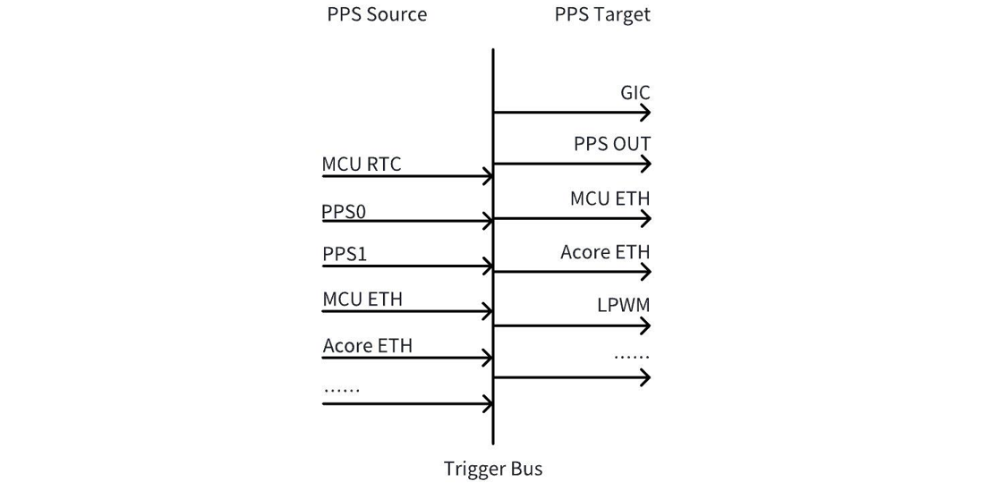
As shown in the figure above, PPS on the S100 can be divided into PPS Source and PPS Target. The PPS Source generates PPS signals, which are transmitted via the internal Trigger Bus to the PPS Target. The PPS Target uses the incoming PPS to generate snapshots or LPWM waveforms.
PPS Target
PPS Target refers to the entity triggered by PPS, used to generate snapshots or LPWM waveforms. On the S100, the main PPS-triggered targets include:
PPS OUT: The PPS2 pin is multiplexed as PPS OUT by default in the current software version, meaning the internal PPS signal can be output externally through this pad.
GIC: In the current software version, interrupts from MCU RTC, PPS0, PPS1, PPS2, and MCU ETH PPS are routed to the GIC by default.
Acore ETH: Acore ETH can accept a PPS source and use it to timestamp its own hardware (generate a snapshot).
LPWM: LPWM can accept a PPS source input and generate corresponding LPWM waveforms based on the PPS.
PPS Source
The S100 offers multiple PPS sources, among which the commonly used ones are listed below (others are reserved):
Index 0: MCU RTC PPS – PPS output from the MCU-side RTC. Enabled by default in the current software version, with a period of 1 pulse per second.
Index 2: PPS0 – a PPS pad that can be used to input external PPS signals (e.g., from GPS) into the chip.
Index 3: PPS1 – a PPS pad that can be used to input external PPS signals (e.g., from GPS) into the chip.
Index 4: PPS2 – a PPS pad that can either input external PPS signals (e.g., from GPS) or output internal PPS signals externally.
Index 8: Acore Eth0 PPS – PPS generated by Acore Eth0, supporting flexible periods (e.g., 1 pulse per second, 1 pulse every 400 ms, etc.).
Index 9: Acore Eth1 PPS – PPS generated by Acore Eth1, supporting flexible periods (e.g., 1 pulse per second, 1 pulse every 400 ms, etc.).
Index 10: MCU Eth PPS – PPS output from the MCU-side Ethernet. Enabled by default in the current software version, with a period of 1 pulse per second.
PPS PAD Configuration
In the current software version, PPS0 and PPS1 are configured by default as PPS inputs (PPS IN) to receive external PPS signals (e.g., from GPS). PPS2 is configured by default as a PPS output (PPS OUT) to export the S100’s internal PPS signal externally. These configurations are handled by the Port module on the MCU side. To modify them, changes must be made within the Port module.
Acore Eth PPS Introduction
Acore Eth PPS supports two output modes: flex mode and fix mode. By default, the system boots into fix mode. You can switch to flex mode using the ethtool command described below. To revert to fix mode, restart the network interface or reboot the system.
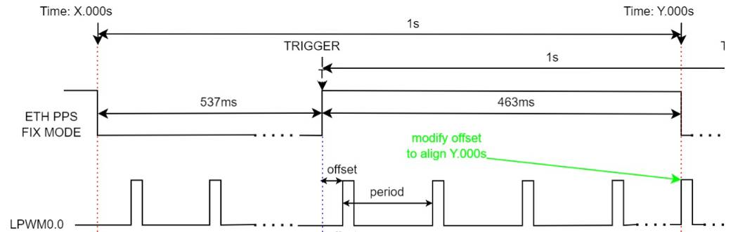
Flex mode: A flexible PPS mode where start/end time, period, and duty cycle can be freely configured. Its rising edge aligns with whole-second timestamps, and PPS output does not change with PHC time adjustments. In the current software version, the duty cycle is fixed at 1%, while the period can be flexibly configured (common values include 1s and 400ms).
Fixed mode: A fixed PPS mode with a fixed period and a fixed duty cycle of 46.3129%. PPS output changes along with PHC time adjustments. In the current software version, it supports a 1-second period, with the whole-second timestamp aligned to the falling edge. After a 536.871ms low-level period, it outputs a 463.129ms high-level pulse.
Configuration for whole-second PPS output:
- In flex mode, if you require PPS output precisely at whole-second timestamps, configure PPS output only after gPTP time synchronization is complete.
- In fixed mode, note that the whole-second timestamp occurs at the falling edge of the ETH PPS signal, while LPWM is synchronized to the ETH PPS rising edge. Therefore, as illustrated in the figure below, you must adjust the LPWM offset accordingly. For example, if the camera runs at 30 FPS (frame interval ≈ 33.333ms), and the PPS rising edge occurs at 536.871ms while the falling edge aligns with the whole second (1s), then to output a frame exactly at the whole-second mark, the required offset is:
offset = 463.129 mod 33.333 ≈ 29.8ms.
Acore Eth PPS Output Configuration Method
Acore Eth PPS output can be configured using the ethtool utility with the following command syntax:
Configure Eth0 PPS output with a 1-second period:
ethtool hobot_gmac --set-flex-pps eth0 index 0 fpps on interval 1000000000;
Configure Eth1 PPS output with a 1-second period:
ethtool hobot_gmac --set-flex-pps eth1 index 0 fpps on interval 1000000000;
To change the output period, modify the last parameter <1000000000>, which is in nanoseconds. For a 400ms period, change it to <400000000>.
When configuring ETH PPS output, note the following two points. The example below illustrates how to modify ETH PPS0 and configure the PPS_INOUT pin as a PPS_OUT function. Adjust configurations according to your specific requirements.
- Modify the default
pps_sourcein the Port configuration:
 static const Port_Lld_PpsConfigType PpsConfig =
 {
     (boolean)TRUE,
-    PPS_SOURCE_AON_RTC,
+    PPS_SOURCE_ETH0_PTP,
 };
- Configure the pin function as PPS_OUT:
-    {(uint8)2, "PPS_OUT", (boolean)TRUE, {(boolean)TRUE, (boolean)FALSE, (boolean)TRUE, (boolean)TRUE, (boolean)TRUE, GPIO, PORT_PIN_CONFIG_TYPE0, PORT_PULL_NONE, PORT_DRIVE_DEFAULT, PORT_PIN_DIR_OUT, PORT_PIN_LEVEL_HIGH}},
+    {(uint8)2, "PPS_OUT", (boolean)TRUE, {(boolean)TRUE, (boolean)FALSE, (boolean)TRUE, (boolean)TRUE, (boolean)TRUE, PPS_OUT, PORT_PIN_CONFIG_TYPE0, PORT_PULL_NONE, PORT_DRIVE_DEFAULT, PORT_PIN_DIR_OUT, PORT_PIN_LEVEL_HIGH}},
These changes are implemented by editing McalCdd/gen_s100_sip_B/Port/src/Port_PBcfg.c. After modification, update the MCU firmware.
MCU Eth PPS Configuration Method
The signal period and pulse width of MCU Eth PPS are set by default in the configuration file Config/McalCdd/gen_s100_sip_B_mcu1/Ethernet/src/Mac_Ip_PBcfg.c, where PpsInterval defaults to 1000 ms and PpsWidth defaults to 10 ms.
Constraints:
- The configuration item
EthGlobalTimeSupportmust be enabled (enabled by default). - The value of
PpsWidthmust be less thanPpsInterval.
After enabling the configuration, verify whether the PPS settings take effect by monitoring changes in the sysfs assert node:
cat /sys/class/pps/pps[4]/assert
Multiple PPS devices appear under /sys/class/pps/. Use the name file to identify which PPS corresponds to the MCU PPS:
cat /sys/class/pps/pps[*]/name
Overall Time Synchronization Solution
Functional Overview
This document uses the S100 as an example to introduce the time synchronization solution. Currently, the MCU mainline supports a single time domain architecture where the time source is connected to the S100 Acore.
Software Architecture Description
Single Time Domain Architecture with Time Source Connected to Acore
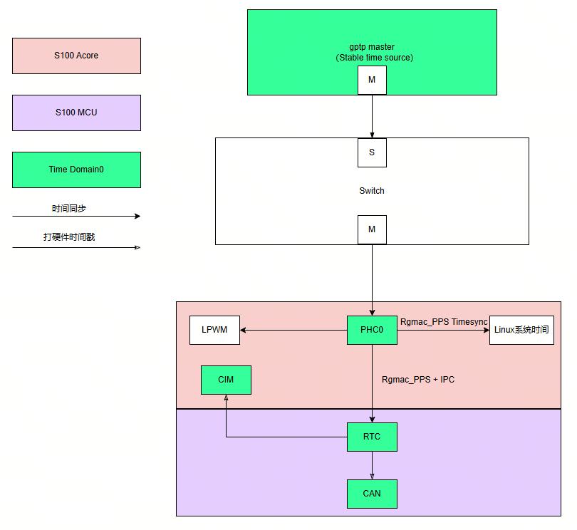
The time synchronization workflow illustrated above can be summarized as follows:
- An external gPTP master device serves as the time source for the entire S100 system.
- First, the
ptp4lsoftware synchronizes the gPTP master’s time to the Acore-side network interface. Then,phc2syscontinuously synchronizes the NIC time to the Linux system time. - Next, the Acore
timesync_sampleapplication synchronizes the NIC time to the MCU-side RTC.
Feature Notes:
- The RTC supports hardware timestamping for CIM and CAN modules shown in the diagram.
- The Acore NIC can generate PPS to trigger LPWM for exposure synchronization.
Code Location and Directory Structure
The Acore-side timesync sample code is located in the project directory:
{sdk_dir}/source/hobot-sp-samples/debian/app/timesync_demo
The MCU-side timesync sample code is located in the project directory:
{mcu_dir}/mcu/Service/TimeSync
Acore Compilation
Compilation Environment
After installing the hobot-sp-samples_*.deb package on the board, the codec_demo source code will be included.
Compilation Instructions
This sample primarily depends on API header files provided by ipcfhal and timesync:
#include "hb_ipcf_hal.h"
#include "hobot_clock_hal.h"
The libraries required for compilation are as follows:
LIBS := -lhbipcfhal -lhbtimesynchal -lpthread -lalog
Compilation command:
On the board, navigate to the /app/timesync_demo/sample_timesync directory and execute:
make
MCU Compilation
Compilation Environment
The MCU-side sample uses the build tools from the MCU codebase. Please refer to: MCU编译.
Build the FreeRTOS image version. Note:
  # Enter the Build/FreeRtos directory
  python build_freertos.py lite matrix B s100 gcc debug # Hardware board or project name
Execution
Supported Platforms
S100
Board Deployment and Configuration
The following preparations are required:
Flash an MCU firmware that supports the time synchronization service on the MCU side.
If running gPTP time synchronization, ensure network connectivity.
To prevent interference from the Linux OS's built-in time synchronization service, disable it by executing the following command:
systemctl stop systemd-timesyncd
Running Guide
Single Time Domain Solution with Time Source Connected to Acore
On the MCU side, modify the configuration in ./Service/TimeSync/src/Hobot_TimeSync.c as follows:
/* Timesync Config Begin */
uint8_t ConfigSource[] = {
    TIMEKEEPER_IPC_INDEX,   // TimeKeeperRTC Source
    TIMEKEEPER_NONE,        // TimeKeeperGPS Source
    TIMEKEEPER_IPC_INDEX,   // TimeKeeperStbmPhc Source
    TIMEKEEPER_NONE,        // TimeKeeperSpi Source
    TIMEKEEPER_NONE,        // TimeKeeperIPC Source
    TIMEKEEPER_NONE,        // TimeKeeperPHC Source
    TIMEKEEPER_NONE         // TimeKeeperGpt Source
};

_Bool EnableTimeKeeper[] = {
    TRUE,
    FALSE,
    FALSE,
    FALSE,
    TRUE,
    FALSE,
    FALSE
};

_Bool Enable_TimeSync_RTC_Once = FALSE;

_Bool Enable_HobotTimesync_Debug = TRUE;
Note that modifications on the MCU side are affected by the PRODUCT_IMAGE macro. For details, please refer to the notes section above.
After flashing and booting, the MCU executes the following commands by default:
The first command sets the PPS trigger source to MCU ETH;
the second command starts the time synchronization service.
  TimeSyncCtrl 4 10
  TimeSyncCtrl 6
To enable MCU-side log printing, use the following command:
TimeSyncCtrl 1
By default, the MCU does not start the time synchronization service automatically. To configure automatic startup, in addition to modifying the configuration described above, you must also add initialization code, as shown below:
TASK(OsTask_SysCore_Startup)
{
  ......
  Timesync_Init();
  ......
}
After completing the above configuration, once the MCU1 firmware is loaded, the time synchronization service will start automatically, and there will be no need to manually execute the TimeSyncCtrl commands.
On the Acore side, execute the following commands:
The first command sets the log level to allow output to the console;
the second command starts PTP time synchronization, synchronizing the external PTP master time to the Acore NIC;
the third command synchronizes the NIC time to the Linux system time;
the fifth command starts the time synchronization program, synchronizing the Acore NIC time to the MCU-side RTC.
export LOGLEVEL=15
ptp4l -i eth0 -f /usr/hobot/lib/pkgconfig/automotive-slave.cfg -m -l 7 > ptp4l.log &
phc2sys -s eth0 -c CLOCK_REALTIME --transportSpecific=1 -m --step_threshold=1000 -w > phc2sys.log &
cd /app/timesync_demo/sample_timesync
./timesync_sample -p 0 -P 4 -r
Key parameter descriptions:
-p 1: Synchronize time of NIC 1; -p 0: Synchronize time of NIC 0 (default)
-r: Synchronize Acore NIC time to MCU RTC time
Acore time synchronization log example:
[INFO][][/app/timesync_demo/sample_timesync/timesync_sample.c:510] ************************************************
[INFO][][/app/timesync_demo/sample_timesync/timesync_sample.c:517] Monotonic_raw time: second = 222, nanosecond = 557846725
[INFO][][/app/timesync_demo/sample_timesync/timesync_sample.c:520] PPS fetch infobuf time: second = 1745925136, nanosecond = 454616475
[INFO][][/app/timesync_demo/sample_timesync/timesync_sample.c:531] rtc snapshot: sec = 1745925136, nsec = 455389596
[INFO][][/app/timesync_demo/sample_timesync/timesync_sample.c:538] ptp0 snapshot: sec = 1745925136, nsec = 455462040
[INFO][][/app/timesync_demo/sample_timesync/timesync_sample.c:582] Timesync Info: timesync ipc send data succeed
[INFO][][/app/timesync_demo/sample_timesync/timesync_sample.c:510] ************************************************
Acore log explanation:
- The "snapshot" field shows the hardware timestamps of various clocks when the MCU NIC emits the PPS pulse.
- The "PPS fetch infobuf time" field indicates the system time captured by the Acore PPS driver.
- The message "timesync ipc send data succeed" confirms that the Acore NIC timestamp was successfully sent to the MCU for time synchronization. The synchronization quality can be checked on the MCU side.
MCU time synchronization log example:
[0162.799758 0]*
[0162.802970 0]RTC snapshot time:1745925071.455114934
[0163.000408 0]Timesync_RecvCallback.
[0163.000661 0]Get Time From Acore success 1745925071 455188935
[0163.001958 0]TimeKeeperRTC and TimeKeeperIPC Offset : - 0s.74001ns
[0163.789774 0]*
MCU log explanation:
- "Get Time From Acore success" indicates that the MCU successfully retrieved time from Acore.
- "TimeKeeperRTC and TimeKeeperIPC Offset" shows the offset applied when synchronizing RTC using IPC time during synchronization.