GPIO Usage
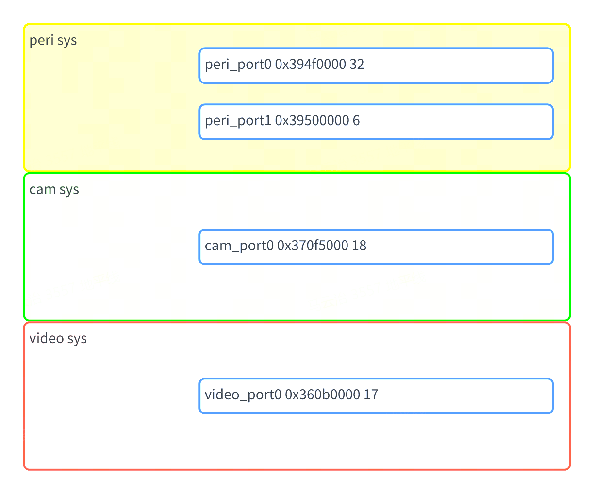
The S100 Acore chip contains three sys GPIO devices: peri, cam, and video. Each device supports up to 32 GPIO pins, and every GPIO pin supports interrupts.
Driver Code
kernel/drivers/gpio/gpio-dwapb.c # GPIO driver source file
Kernel Configuration
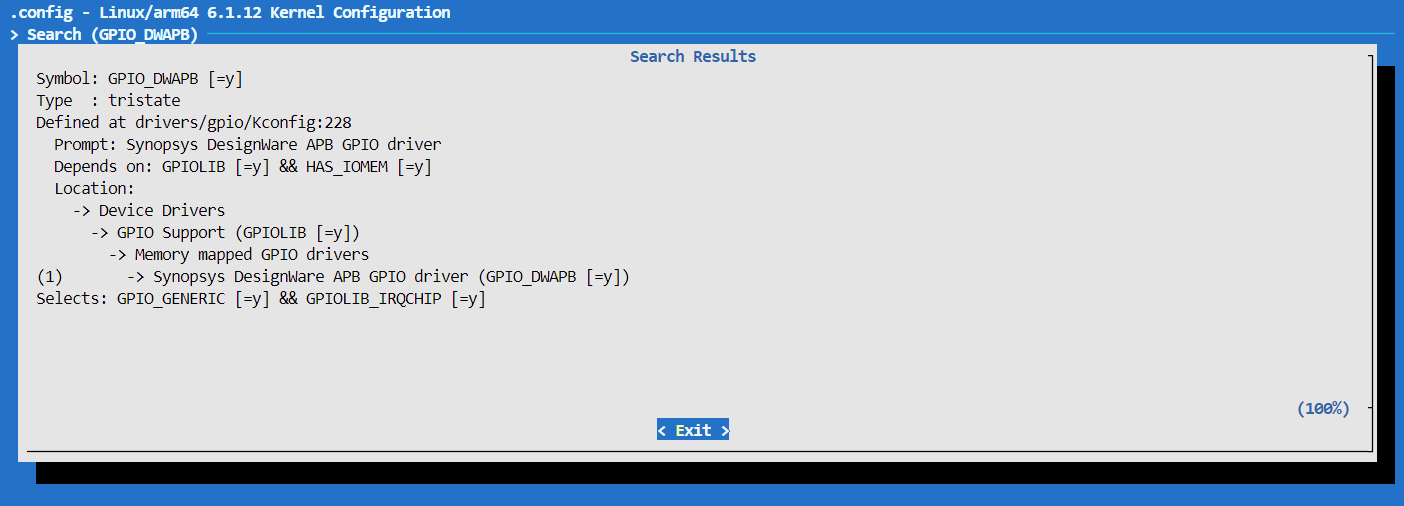
GPIO_DWAPB
Kernel DTS Configuration
The device tree definition for the S100 GPIO controller is located in the file arch/arm64/boot/dts/hobot/drobot-s100-soc.dtsi within the kernel folder of the SDK package.
Nodes in s100.dtsi primarily declare SoC-wide features and are independent of specific circuit boards. They generally do not require modification.
GPIO Usage
Kernel Space
DTS Configuration
GPIO configurations for all S100 pins are defined in the file arch/arm64/boot/dts/hobot/drobot-s100-soc.dtsi within the kernel folder of the SDK package.
When users need to configure a specific pin as a GPIO, they can directly reference the predefined GPIO configurations:
Device tree node properties for GPIO are typically named as <names>-gpios or <names>-gpio. For example:
/**
* peri_port0 represents the first GPIO device of the peri sys.
* The following device node defines four GPIO pins:
*       Pin 16 (0-based) of the first GPIO device in peri sys
*       Pin 17 (0-based) of the second GPIO device in peri sys
*       Pin 28 (0-based) of the first GPIO device in cam sys
*       Pin 18 (0-based) of the first GPIO device in video sys
* GPIO_ACTIVE_HIGH indicates active-high logic, typically set to GPIO_ACTIVE_HIGH.
*/
gpio-test {
        test-gpios = <&peri_port0 16 GPIO_ACTIVE_HIGH
                      &peri_port1 17 GPIO_ACTIVE_HIGH
                      &cam_port0 28 GPIO_ACTIVE_HIGH
                      &video_port0 18 GPIO_ACTIVE_HIGH>;
};
Driver Code APIs
/* include/linux/gpio.h */
/* Request a GPIO */
int gpio_request(unsigned gpio, const char *label);
/* Initialize GPIO as output and set its output level */
int gpio_direction_output(unsigned gpio, int value);
/* Initialize GPIO as input */
int gpio_direction_input(unsigned gpio);
/* Read the GPIO level */
int gpio_get_value(unsigned int gpio);
/* Set the GPIO level */
void gpio_set_value(unsigned int gpio, int value);
/* Release the GPIO */
void gpio_free(unsigned gpio);
/* Request a GPIO interrupt; the returned value can be passed to request_irq and free_irq */
int gpio_to_irq(unsigned int gpio);
User Space
Control Interface
In user space, GPIO operations can be performed via the /sys/class/gpio sysfs interface.
The following nodes exist under the sysfs directory:
# Request a GPIO
echo <gpio_num> > /sys/class/gpio/export
# Release a GPIO
echo <gpio_num> > /sys/class/gpio/unexport
# Set GPIO as output
# When direction is set to 'out', writing 1/0 to 'value' sets high/low level respectively.
echo out > /sys/class/gpio/gpio<gpio_num>/direction
# Set high level
echo 1 > /sys/class/gpio/gpio<gpio_num>/value
# Set low level
echo 0 > /sys/class/gpio/gpio<gpio_num>/value

# Set GPIO as input; when direction is 'in', reading 'value' returns the input level (0 = low, 1 = high).
echo in > /sys/class/gpio/gpio<gpio_num>/direction
# Read the external GPIO value
cat /sys/class/gpio/gpio<gpio_num>/value


# View GPIO debug information
cat /sys/kernel/debug/gpio

# View the relationship between GPIO and pinctrl
# Shows the mapping between system pins and GPIO numbers
cat /sys/kernel/debug/pinctrl/<pinctrl_dev>/gpio-ranges
sysfs Interface Overview
export & unexport
The nodes /sys/class/gpio/export and /sys/class/gpio/unexport are write-only.
User programs request kernel to export control of a specific GPIO to user space by writing the GPIO number, provided that no kernel code has already claimed this GPIO. For example, to request GPIO number 480:
echo 480 > export
This operation creates a directory named gpio480 under /sys/class/gpio.
/sys/class/gpio/unexport performs the opposite action. For example, to remove the gpio480 node:
echo 480 > unexport # This removes the gpio480 node and releases GPIO number 480.
direction
The direction file indicates the GPIO direction. Reading it returns either in or out. Writing out configures the GPIO as an output; writing in configures it as an input.
value
- When direction is set to
in, readingvaluereturns the input level (0 = low, 1 = high). - When direction is set to
out, writing1or0tovaluesets the output to high or low level, respectively.
edge
To configure interrupts from user space, set direction to in, then write an appropriate value to the edge file.
Value of edge | Meaning |
|---|---|
| none | Pin is configured as input but not as an interrupt pin |
| rising | Pin is an interrupt input triggered on rising edge |
| falling | Pin is an interrupt input triggered on falling edge |
| both | Pin is an interrupt input triggered on both edges |
Debugging
cat /sys/kernel/debug/gpio
Querying this node provides information about currently used GPIOs and their states (in, out, IRQ).
root@ubuntu:~# cat /sys/kernel/debug/gpio
gpiochip4: GPIOs 423-438, parent: i2c/3-0076, 3-0076, can sleep:
gpio-423 (                    |io-ser-reset0       ) out hi
gpio-424 (                    |io-ser-reset1       ) out hi
gpio-425 (                    |io-ser-reset2       ) out hi
gpio-426 (                    |io-ser-reset3       ) out hi

gpiochip3: GPIOs 439-455, parent: platform/360b0000.gpio, 360b0000.gpio:

gpiochip2: GPIOs 456-473, parent: platform/370f5000.gpio, 370f5000.gpio:

gpiochip1: GPIOs 474-479, parent: platform/39500000.gpio, 39500000.gpio:

gpiochip0: GPIOs 480-511, parent: platform/394f0000.gpio, 394f0000.gpio:
gpio-481 (                    |sysfs               ) out hi ACTIVE LOW
gpio-491 (                    |sysfs               ) in  hi
gpio-495 (                    |sysfs               ) in  hi
gpio-496 (                    |sysfs               ) in  hi
gpio-498 (                    |sysfs               ) in  hi
gpio-503 (                    |io-ext-reset        ) out lo
root@ubuntu:~#
Determining gpio-index
kernel_index = base + offset, where base is obtained from /sys/class/gpio or /sys/kernel/debug/gpio, and offset is obtained from the DTS.
Take pin sensor8_err as an example: by examining drobot-s100-pinctrl.dtsi, we find that sensor8_err corresponds to GPIO chip video_port0: gpio@360b0000 with an offset of 13.
Checking /sys/kernel/debug/gpio, we see that video_port0: gpio@360b0000 has a base of 439.
Thus, the kernel GPIO index for sensor8_err is: 439 + 13 = 452.
Check drobot-s100-pinctrl.dtsi to obtain offset and base
From the device tree below, we can see that sensor8_err corresponds to video_sensor8_err, and its associated GPIO chip is "video_port0: gpio@360b0000".The offset of video_gnss_int is 0, and offsets increment sequentially; therefore, the offset of video_sensor8_err is 13.
pinctrl_video: pinctrl@36090000 {
   compatible = "drobot,s100-pinctrl";
   reg = <0x0 0x36090000 0x0 0x1000>,
         <0x0 0x360a0000 0x0 0x1000>;
   pctldev-name = "video";
   status = "okay";

   video_gpio: video_gpio_func {
      pinmux {
         function = "video_gpio";
         pins = "video_gnss_int", "video_peri_rsto",
                  "video_cam_pint", "video_sd_1v8", "video_sd_bus_pow",
                  "video_sensor0_err", "video_sensor1_err",
                  "video_sensor2_err", "video_sensor3_err", "video_sensor4_err",
                  "video_sensor5_err", "video_sensor6_err",
                  "video_sensor7_err", "video_sensor8_err",
                  "video_sensor9_err", "video_sensor10_err", "video_sensor11_err";
      };
      pinconf {
         pins = "video_gnss_int", "video_peri_rsto",
                  "video_cam_pint", "video_sd_1v8", "video_sd_bus_pow",
                  "video_sensor0_err", "video_sensor1_err",
                  "video_sensor2_err", "video_sensor3_err", "video_sensor4_err",
                  "video_sensor5_err", "video_sensor6_err",
                  "video_sensor7_err", "video_sensor8_err",
                  "video_sensor9_err", "video_sensor10_err", "video_sensor11_err";
         drive-strength = <1>;
      };
   };
}
For example, in this line: gpiochip3: GPIOs 439-455, parent: platform/360b0000.gpio,
360b0000.gpio:"GPIOs 439-455" indicates that the base is 439.
cat /sys/kernel/debug/gpio
root@ubuntu:~# cat /sys/kernel/debug/gpio
gpiochip4: GPIOs 423-438, parent: i2c/3-0076, 3-0076, can sleep:
gpio-423 (                    |io-ser-reset0       ) out hi
gpio-424 (                    |io-ser-reset1       ) out hi
gpio-425 (                    |io-ser-reset2       ) out hi
gpio-426 (                    |io-ser-reset3       ) out hi

gpiochip3: GPIOs 439-455, parent: platform/360b0000.gpio, 360b0000.gpio:

gpiochip2: GPIOs 456-473, parent: platform/370f5000.gpio, 370f5000.gpio:
gpio-464 (                    |scl                 ) out lo
gpio-465 (                    |sda                 ) in  lo
gpio-466 (                    |scl                 ) out lo
gpio-467 (                    |sda                 ) in  lo
gpio-468 (                    |scl                 ) out lo
gpio-469 (                    |sda                 ) in  lo
gpio-470 (                    |scl                 ) out lo
gpio-471 (                    |sda                 ) in  lo
gpio-472 (                    |scl                 ) out lo
gpio-473 (                    |sda                 ) in  lo

gpiochip1: GPIOs 474-479, parent: platform/39500000.gpio, 39500000.gpio:

gpiochip0: GPIOs 480-511, parent: platform/394f0000.gpio, 394f0000.gpio:
gpio-495 (                    |scl                 ) out lo
gpio-496 (                    |sda                 ) in  lo
gpio-503 (                    |io-ext-reset        ) out lo