Audio Debugging Guide
This chapter mainly covers the basic features of S100 I2S, fundamental voice/audio knowledge, and instructions for adding a codec and debugging sound cards.
Overview
CPU DAI: Digital Audio Interface on the CPU side, typically an I2S interface, controlling bus transmission.
CODEC DAI: Refers to the codec itself. It manages the codec workflow and provides interfaces to the core layer.
DAI LINK: Binds CPU DAI and CODEC DAI, representing the hardware controller driver.
PLATFORM: Specifies the platform driver on the CPU side, usually a DMA driver used for data transmission.
DAPM: Dynamic Audio Power Management.
Audio Development Instructions
A complete sound card consists of CPU DAI, CODEC DAI, PLATFORM, and SOUND CARD.
- CPU DAI driver: Typically an I2S interface driver.
- CODEC DAI driver: Refers to the external codec driver.
- PLATFORM driver: Usually a DMA driver responsible for managing audio data.
- SOUND CARD driver: Responsible for connecting CPU DAI and CODEC DAI, e.g.,
sound/soc/hobot/hobot-snd-s100-ac-fdx-host.c.
I2S Parameter Specifications
Capabilities supported by the S100 I2S module:
- Channel support: 1/2/4/8/16 channels.
- Sample rate support: 8k/16k/32k/48k/44.1k/96k/192k.
- Sample precision support: 8bit/16bit/24bit/32bit.
- Transmission protocol support: I2S/DSP (TDM).
- I2S mode: Supports configuration as either master or slave mode.
- SYSCLK requirement: The I2S module’s SYSCLK must be at least 6 times the BCLK frequency.
- Full-duplex support: In full-duplex mode, SDIO0 is input and SDIO1 is output; this cannot be changed.
- BCLK limit: BCLK output must not exceed 25 MHz.
Adding a New Codec
Add Codec Driver
Place the newly added codec driver file under the sound/soc/codecs/ directory.
Add Build Configuration
- Modify
sound/soc/codecs/KconfigandMakefileto include the codec driver in the build configuration.
Example addition to Kconfig:
config SND_SOC_ES7210
        tristate "ES7210 Audio Codec"
        depends on I2C
Example addition to Makefile:
obj-$(CONFIG_SND_SOC_ES7210) += snd-soc-es7210.o
- Enable the codec driver via
menuconfig:
sudo ./mk_kernel.sh menuconfig
After running the above command, open the Kernel Configuration interface, search for CONFIG_SND_SOC_ES7210, and enable it.
Modify Device Tree Source (DTS)
DTS modifications typically involve the following:
- Add a codec driver node. Since codecs are usually controlled via I2C, add codec information under the corresponding I2C node. Example:
i2c5: i2c@39470000 {
    es7210_0: es7210_0@40 {
            compatible = "MicArray_0";
            reg = <0x40>;
            #sound-dai-cells = <1>;
            channels = <8>;
            adc_dev_num = <2>;
            status = "okay";
    };
};
- Add a sound card node to establish the DAI link binding between the codec and I2S. Example:
snd2: snd2 {
        status = "okay";
        model = "s100snd2";
        compatible = "hobot, s100-snd-ac-fdx-master";
        i2s_mode = <1>;/*1:i2s mode; 7:dsp_a mode*/
        work_mode = <1>;/*0:half-duplex; 1:full-duplex*/
        channel_max = <2>;
        mclk_set = <24576000>;
        dai-link@0 {
                dai-format = "dsp_a"; //"i2s"/"dsp_a" // corresponds to SND_SOC_DAIFMT_DSP_A
                // bitclock-master; // Configuring *-master corresponds to dai_fmt equivalent to SND_SOC_DAIFMT_CBM_CFM, indicating the codec provides the clock source
                // frame-master;
                // frame-inversion; // Corresponds to SND_SOC_DAIFMT_NB_IF, inverting frame sync signal polarity. Normally, left channel = low level, right channel = high level. Polarity reverses when frame-inversion is enabled.
                link-name = "s100dailink0";
                cpu {
                        sound-dai = <&i2s0 0>; // Digital audio interface, controls bus transmission
                };
                codec {
                        sound-dai = <&es7210_0 0>; // Codec chip interface
                };
        };

        dai-link@1 {
                dai-format = "dsp_a";
                link-name = "s100dailink1";
                cpu {
                        sound-dai = <&i2s0 1>;
                };
                codec {
                        sound-dai = <&es8156>;
                };
        };
};
- Additionally, a
dummy_codecnode is added in the DTS. When no external codec is present or the codec requires standalone configuration independent of the ALSA framework, a virtual codec-bound sound card device is registered to allow user-space creation of device nodes for controlling I2S/DMA.
Debugging Instructions
Sound Card Debugging
This section describes sound card debugging based on the S100 with Waveshare audio daughterboard.
On S100, the sound card modules are provided as loadable kernel modules (.ko) and mounted dynamically. Use the following commands to load them:
modprobe hobot_cpudai_super
modprobe snd-soc-es8156
modprobe snd-soc-es7210
modprobe hobot_snd_s100_ac_fdx_host
After loading the drivers, verify successful sound card registration using:
- Check
/proc/asound/cards:
root@ubuntu:/# cat /proc/asound/cards
 0 [s100snd2       ]: s100snd2 - s100snd2
                      s100snd2
- Check
/dev/snd/:
root@ubuntu:/# ls -l /dev/snd
total 0
crw-rw-r--+ 1 root misc 116,  4 Apr 29 19:09 controlC0
crw-rw-r--+ 1 root misc 116,  2 Apr 29 19:09 pcmC0D0c
crw-rw-r--+ 1 root misc 116,  3 Apr 29 19:09 pcmC0D1p
After successful sound card loading, test functionality with the following commands:
arecord -Dhw:0,0 -c 2 -r 16000 -f S16_LE -t wav -d 5 test.wav
aplay -Dhw:0,1 test.wav
The PDMA driver requires data size to be aligned to 64-byte boundaries.
When configuring the period-size value, ensure it satisfies this alignment requirement.
For arecord/aplay, use the parameter: --period-size=X
Common Debugging Techniques
Adjust Debug Log Level
echo "8 4 1 7" > /proc/sys/kernel/printk
echo -n "file hobot-cpudai-super.c +p" > /sys/kernel/debug/dynamic_debug/control
echo -n "file hobot-i2s-super.c +p" > /sys/kernel/debug/dynamic_debug/control
echo -n "file hobot-platform-super.c +p" > /sys/kernel/debug/dynamic_debug/control
ALSA procfs Node Description
procfs is a Linux filesystem that provides interfaces to kernel data structures. It is mounted at /proc.
The ALSA procfs mount point is: /proc/asound. ALSA uses files under /proc/asound to store device information and for control purposes. Through these proc nodes, we can quickly inspect certain information to help diagnose and debug issues.
/proc/asound/cards
Lists all registered sound cards. By checking this node, you can verify the list of sound cards currently registered in the system or confirm whether a sound card has been successfully registered.
/proc/asound/pcm
Displays information about allocated PCM stream devices. By examining this node, you can identify the list of devices supported by the current sound card. This helps determine appropriate card/device values when configuring device nodes during testing.
/proc/asound/cardX/pcmY[c,p]/*
Each PCM stream device associated with a sound card in the system has a corresponding procfs directory structured as shown above. Here:
- X represents the sound card number, which can be confirmed via /proc/asound/cards or device nodes under /dev/snd.
- Y represents the device number, which can be confirmed via /proc/asound/pcm or device nodes under /dev/snd.
- c/p stands for capture/playback respectively.
This directory allows viewing PCM device information and status.
info
General information about the PCM stream, such as sound card number, device number, stream type, bound codec type, etc.
hw_params
When the PCM stream is open, you can view basic hardware parameter configurations here, such as sample rate, bit width, number of channels, period_size, buffer_size, etc. Note that the configured period_size and buffer_size might differ from the values displayed here; the actual hardware parameters shown here should be considered authoritative.
root@ubuntu:/proc/asound/card0/pcm0c/sub0# cat hw_params
access: RW_INTERLEAVED
format: S16_LE
subformat: STD
channels: 2
rate: 48000 (48000/1)
period_size: 1024
buffer_size: 4096
sw_params
When the PCM stream is open, you can view software parameters such as start_threshold, stop_threshold, and silence_threshold. Pay special attention to start_threshold and stop_threshold.
- start_threshold: If set too high, there will be a long delay between playback start and audible output, potentially causing very short audio clips to be missed entirely.
- stop_threshold: Determines the condition for triggering an xrun. An xrun occurs when available buffer space exceeds this threshold.
root@ubuntu:/proc/asound/card0/pcm0c/sub0# cat sw_params
tstamp_mode: ENABLE
period_step: 1
avail_min: 1
start_threshold: 1
stop_threshold: 40960
silence_threshold: 0
silence_size: 0
boundary: 4611686018427387904
status
Shows the current substream status (e.g., running, xrun) and values of appl_ptr/hw_ptr pointers. The hw_ptr and appl_ptr can help identify situations where the underlying hardware fails to transmit or receive any data.
For example, if a test starts but interrupts are not triggered properly, data transfer will stall, and hw_ptr/appl_ptr will cease updating.
xrun
During audio playback, intermittent or continuous crackling, popping, or stuttering noises typically indicate an xrun. Xruns (frame drops) are unavoidable under system performance constraints. A certain frame drop rate may be acceptable depending on the use case, and optimization techniques can help minimize occurrences. However, if xruns happen frequently and cannot recover, code implementation flaws must be investigated.
Scenarios Where xrun May Occur
During playback, the application continuously writes audio data into the driver buffer, which is then sent via I2S FIFO to the codec for playback. If the application writes too slowly, causing the driver buffer to become empty, an underrun occurs, leading to frame drops and potential audio anomalies.
During recording, digital signals converted by the codec are written via I2S FIFO into the driver buffer, and the application reads audio data from this buffer. If the application reads slower than data is written, exceeding the stop_threshold triggers an overrun.
Diagnosing xrun
Check if xrun is caused by time-consuming I/O operations:
- Write audio files to a RAM disk or specific device file, using commands like:
Write to RAM disk:
mkdir /data/audio_test
tinycap /data/audio_test/test.wav

Specific device file:
tinycap /dev/null
Note: The above methods only help determine if I/O latency causes xrun; they are not solutions to fix xrun.
- Optimize application testing:
Use a dedicated thread for media storage access and PCM device I/O.
For recording, create a separate thread for file writing along with a ring buffer (adjustable size). Data from pcm_read is written into the ring buffer, and fwrite reads from it. As long as fwrite’s blocking time stays within the ring buffer’s capacity, xrun-induced data loss can be avoided.
- Use /proc configuration features to inspect information:
Enable the xrun_debug config options during kernel compilation and reflash the image. (If xrun_debug already exists, the feature is enabled—no need to recompile.)
CONFIG_SND_PCM_XRUN_DEBUG=y
CONFIG_SND_VERBOSE_PROCFS=y
CONFIG_SND_DEBUG=y
The corresponding proc node is located at: /proc/asound/cardX/pcmY[c,p]/xrun_debug
For example, writing "3" to xrun_debug enables basic debugging and stack dumping, helping identify if the PCM stream stopped due to specific reasons:
# Enable basic debugging and dump stack
# Useful to check if PCM stream stops (often due to incorrect audio process timing from scheduler)
echo 3 > /proc/asound/card0/pcm0p/xrun_debug
Fixing xrun
- Increase thread priority (use real-time threads with higher priority values).
- Increase period_size to adjust DMA transfer volume.
- Implement asynchronous I/O and ALSA device read/write operations.
Common Issues
Device Node Opening Errors
-
Unable to open PCM device (cannot open device '/dev/snd/pcmC0D3c': No such file or directory)
- Driver failed to load, so no device node was created under /dev/snd.
- Incorrect card/device values specified, leading to failure in locating the corresponding device node.
Possible reasons for missing device nodes under /dev/snd:
- I2S/codec driver failed to load. Check dmesg for messages like:
soc:sndcard@0: BUG: Can't get codec
soc:sndcard@0: BUG: Can't get cpu
probe of soc:sndcard@0 failed with error -22
-
In the device tree source (DTS), the
statusproperty of relevant driver nodes isn’t set to "okay", preventing driver initialization. After driver loading, check dmesg for success messages like "successfully registered cpu dai0 driver". -
Unable to open PCM device (cannot set hw params: Unknown error -22)
The parameters set during testing exceed the intersection of supported ranges (rate, format, channels) defined in snd_soc_dai_driver for both I2S and codec drivers.
- Application hangs when opening device node with no log output
ALSA framework allows only one open instance per device at a time. Check if the application was previously launched and hasn’t exited before starting again.
Recording/Playback Issues
- pcm_read/pcm_write returns error code -5
Increase ALSA framework log level to check if missing interrupts or hardware link issues prevent interrupt generation:
echo "8 4 1 7" > /proc/sys/kernel/printk
echo -n "file pcm_lib.c +p" > /sys/kernel/debug/dynamic_debug/control
If the message write error (DMA or IRQ trouble?) appears, it indicates missing interrupts. Inspect register configurations and hardware connections.
- pcm_read/pcm_write returns error code -32
Usually indicates an xrun.
- pcm_read returns error code -16
During normal recording (with S100 as slave), this error occurs if the clock signal suddenly disappears or the hardware connection is interrupted.
-
Recorded data is all zeros or no sound during playback
- Use an oscilloscope to verify I2S clock line frequency and check if data lines carry valid signals.
- If clock frequency is unexpected or a clock signal remains constantly low, verify I2S register configurations (e.g., master/slave mode, clock ratios).
- If the above checks pass, verify if the codec chip functions correctly. Play a sine wave and measure analog output from the codec. If no output is detected, confirm codec clock ratio settings match J5 pin requirements and that S100’s current clock ratio falls within the codec’s supported range.
- If the codec outputs a clean signal, check if the amplifier chip works properly by verifying voltage levels on its pins.
-
Recording/Playback noise
Some codec designs require the codec’s master clock (MCLK) to be synchronous with BCLK/LRCLK when operating in slave mode. Otherwise, data glitches or repetitions during recording may cause noise.
Audio Daughterboard Usage Guide
Audio Daughterboard Overview
The audio daughterboard connects to the S100 development board and receives a single full-duplex I2S signal.
It includes:
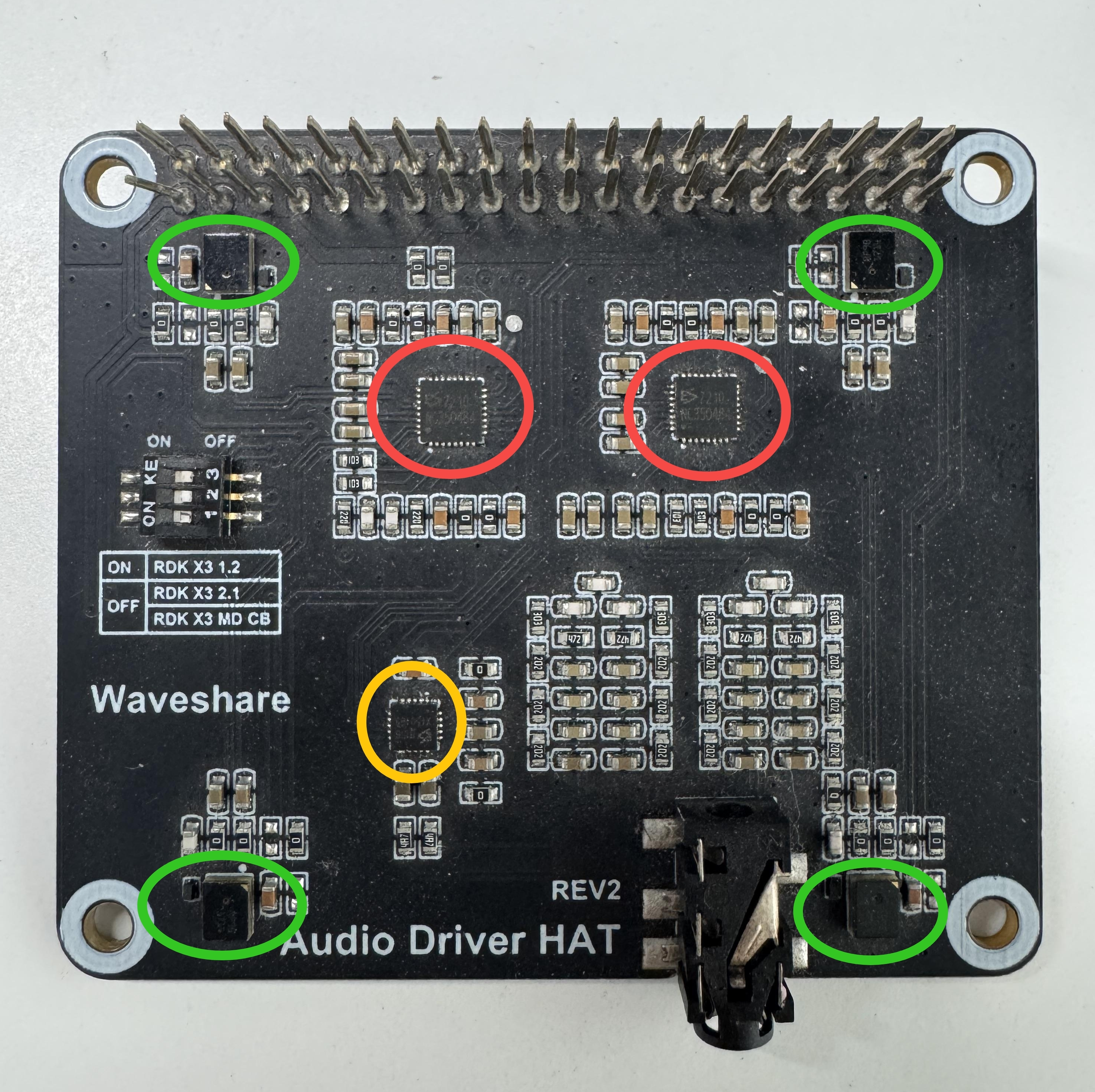
- Two ES7210 chips (I2C addresses 0x40 and 0x42), supporting 8-channel recording: 4 channels for analog microphones and 2 channels for AEC loopback from speakers.
- One ES8156 chip (I2C address 0x08), supporting 2-channel playback to headphones or speakers.
Physical layout (see image below): red circles mark ES7210 chips, yellow circle marks ES8156, and green circle marks the 4-mic array.
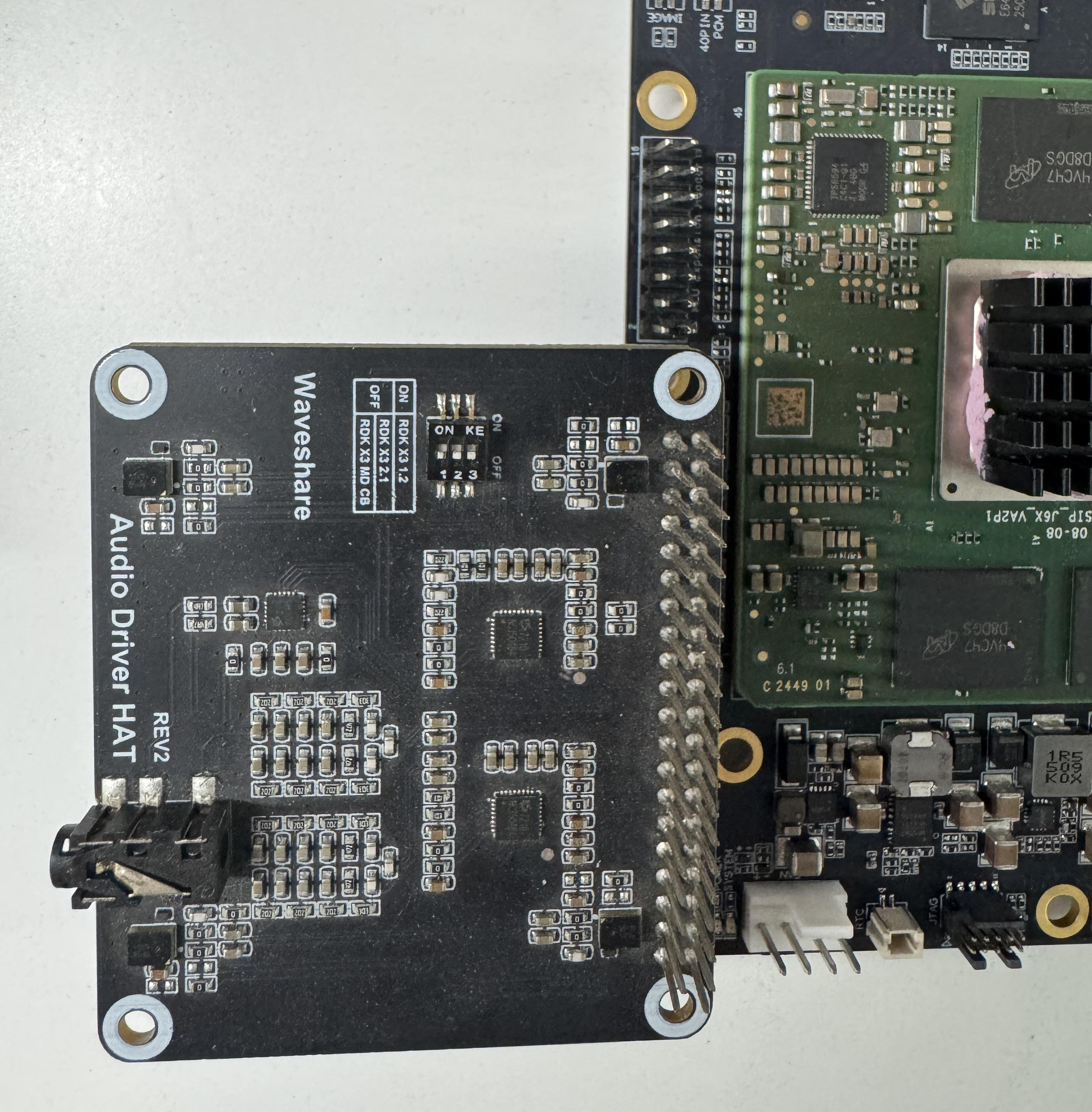
Connecting the Audio Daughterboard to the Development Board
Connection method shown below:
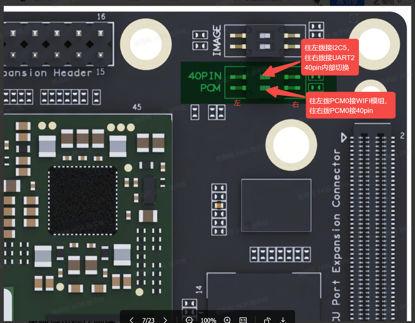
 Note: The PCM pins on the 40-pin header are shared with the PCIe Wi-Fi module. A DIP switch is provided on the hardware to toggle the pin functionality.
The DIP switch configuration for pin function selection is illustrated in the following figure: