Stereo Depth Estimation Algorithm
1. Feature Introduction
The Digua binocular depth estimation algorithm takes stereo image data as input and outputs the disparity map and depth map corresponding to the left view. Inspired by the IGEV network, the algorithm adopts a GRU architecture, offering strong data generalization capability and high inference efficiency.
Stereo algorithm code repository: https://github.com/D-Robotics/hobot_stereonet
MIPI camera code repository: https://github.com/D-Robotics/hobot_mipi_cam
ZED camera code repository: https://github.com/D-Robotics/hobot_zed_cam
Algorithm tutorial: Live Replay | Practical Deployment of AI Binocular Algorithm on RDK X5
2. Supported Platforms
| Platform | OS Support | Example Functionality |
|---|---|---|
| RDK X5, RDK X5 Module | Ubuntu 22.04 (Humble) | Launch stereo camera, perform depth inference, and display results on Web UI |
| RDK S100, RDK S100P | Ubuntu 22.04 (Humble) | Launch stereo camera, perform depth inference, and display results on Web UI |
3. Model Versions
| Platform | Algorithm Version | Quantization | Input Size | Max Inference FPS | Model Description |
|---|---|---|---|---|---|
| X5 | V2.0 | int16 | 640x352x3x2 | 15 | Legacy version |
| X5 | V2.1 | int16 | 640x352x3x2 | 15 | Legacy version with confidence output |
| X5 | V2.2 | int8 | 640x352x3x2 | 23 | Legacy version |
| X5 | V2.3 | int8 | 640x352x3x2 | 27 | Legacy version with highest FPS |
| X5 | V2.4_int16 | int16 | 640x352x3x2 | 15 | Current main version, high-accuracy depth estimation |
| X5 | V2.4_int8 | int8 | 640x352x3x2 | 23 | Current main version, high-FPS depth estimation |
| X5 | V2.5_int16 | int16 | 640x352x3x2 | 16 | Latest version, high-accuracy depth estimation |
| X5 | V2.5_int16_96 | int16 | 640x352x3x2 | 18 | Latest version, max disparity search range = 96 |
| X5 | V2.5_int16_544_448 | int16 | 544x448x3x2 | 15 | Latest version, resolution 544×448 |
| X5 | V2.5_int16_544_448_96 | int16 | 544x448x3x2 | 17 | Latest version, resolution 544×448, max disparity search range = 96 |
| S100 | V2.1 | int16 | 640x352x3x2 | 53 | Legacy version with confidence output |
| S100 | V2.4 | int16 | 640x352x3x2 | 53 | Current main version with confidence output |
4. Prerequisites
4.1. RDK Platform
- RDK has been flashed with the RDK OS system.
- TogetheROS.Bot has been successfully installed on the RDK.
- For online inference, prepare a stereo camera. Currently supported cameras include multiple MIPI models and ZED Mini/2i USB cameras.
- For offline inference, prepare stereo image data.
- Ensure your PC can access the RDK over the network.
4.2. System and Package Versions
| Version | Verification Command | |
|---|---|---|
| RDK X5 system image version | 3.3.3 or later | cat /etc/version |
| RDK S100 system image version | 4.0.2-Beta or later | cat /etc/version |
| tros-humble-hobot-stereonet package version | 2.5.0 or later | apt list | grep tros-humble-hobot-stereonet/ |
| tros-humble-mipi-cam package version | 2.3.13 or later | apt list | grep tros-humble-mipi-cam/ |
| tros-humble-hobot-zed-cam package version | 2.3.3 or later | apt list | grep tros-humble-hobot-zed-cam/ |
- If the system image version does not meet requirements, refer to the corresponding section in the documentation for re-flashing instructions.
- If package versions are outdated, run the following commands to upgrade:
sudo apt update
sudo apt install --only-upgrade tros-humble-hobot-stereonet
sudo apt install --only-upgrade tros-humble-mipi-cam
sudo apt install --only-upgrade tros-humble-hobot-zed-cam
- If the above instructions fail to update the program to the latest version, you need to modify the apt source file to the beta source:
# To switch to the beta source, execute the following commands:
sudo echo 'deb [signed-by=/usr/share/keyrings/sunrise.gpg] http://archive.d-robotics.cc/ubuntu-rdk-x5-beta  jammy main' | sudo tee /etc/apt/sources.list.d/sunrise.list
apt update

# To switch back to the official release source, execute the following commands:
sudo echo 'deb [signed-by=/usr/share/keyrings/sunrise.gpg] http://archive.d-robotics.cc/ubuntu-rdk-x5  jammy main' | sudo tee /etc/apt/sources.list.d/sunrise.list
apt update
If the sudo apt update command fails or returns errors, refer to the FAQ section: Q10: How to resolve issues when apt update fails or reports errors?.
5. Launching the Algorithm
5.1. Important Notes (MUST READ!!!)
Please execute all commands in this document as the root user. Using other users may result in insufficient permissions and unnecessary errors.
5.2. Installing MIPI Stereo Cameras
(1) 230AI MIPI Stereo Camera
- The official RDK 230AI MIPI stereo camera is shown below:
Note: Please check the silk screen marking on the back of the camera labeled CDPxxx-V3/V4 to confirm it is version V3 or V4.
- Installation on RDK X5 is shown below:
- Installation on RDK S100 is shown below. Note that the DIP switches on the S100 CAM daughterboard must be set to
LPWMand3.3V:

(2) 132GS MIPI Stereo Camera
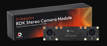
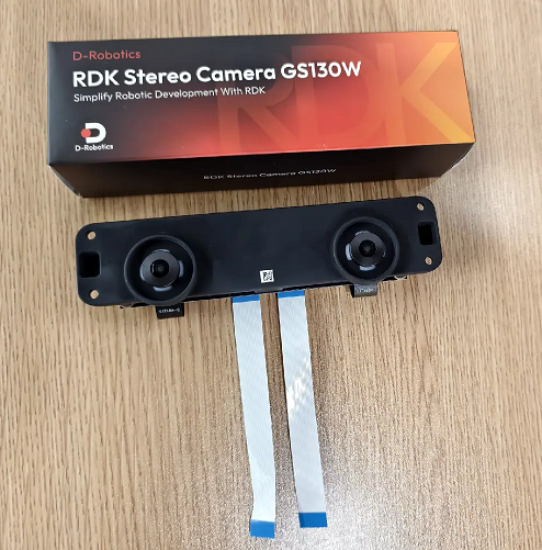
- The official RDK 132GS MIPI stereo camera is shown below:
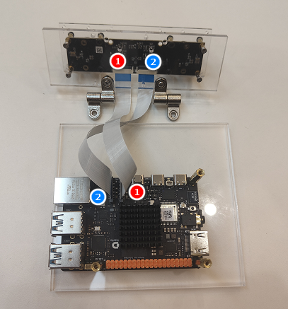
- Installation on RDK X5 is shown below:
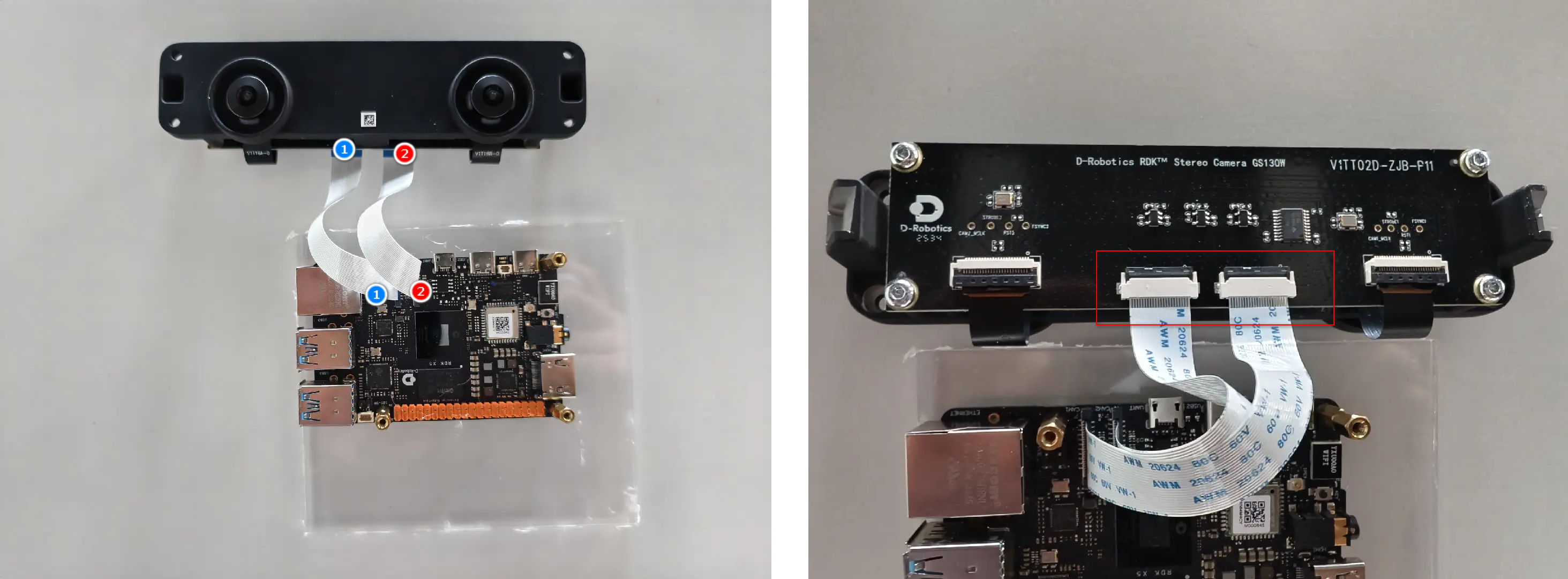
- The latest cable has been upgraded. Note that the cable is directional: connect the CAM end to the camera and the RDK end to the development board.(White and black wires are both functional and will be shipped at random.)

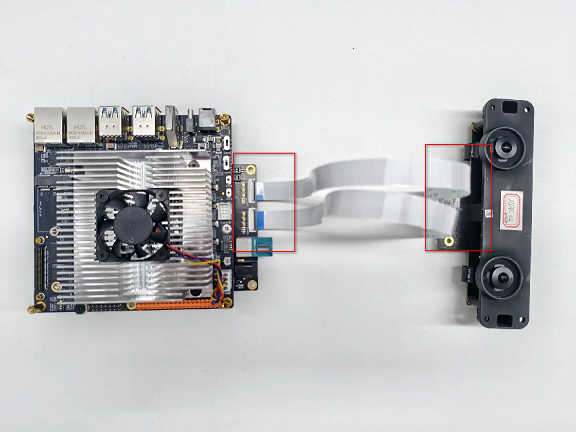
- Installation on RDK S100 is shown below. Note that the DIP switches on the S100 CAM daughterboard must be set to
LPWMand3.3V:
5.3. Online Launch Commands
(1) Verify MIPI Stereo Camera I2C Signals
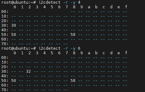
- To verify whether the 230AI stereo camera I2C signals are functioning properly, SSH into the RDK and run the following commands. If addresses such as 0x30, 0x32, and 0x50 appear in the output, the camera connection is normal:
# RDK X5
i2cdetect -r -y 4
i2cdetect -r -y 6

# RDK S100
i2cdetect -r -y 1
i2cdetect -r -y 2
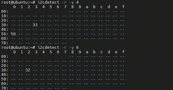
- To verify whether the 132GS stereo camera I2C signals are functioning properly, SSH into the RDK and run the following commands. If addresses such as 0x32, 0x33, and 0x50 appear in the output, the camera connection is normal:
# RDK X5
i2cdetect -r -y 4
i2cdetect -r -y 6

# RDK S100
i2cdetect -r -y 1
i2cdetect -r -y 2
If I2C signals cannot be detected, the camera will not function properly.
(2) Verify Camera Stream Output
- Method 1: If the
tros-humble-hobot-stereonetpackage is already installed, you can directly copy the script:
cp -rv /opt/tros/humble/share/hobot_stereonet/script/run_cam.sh ./
- Method 2: Manually create a launch script named
run_cam.shand add the following content:
#!/bin/bash
source /opt/tros/humble/setup.bash

ros2 pkg prefix mipi_cam

image_width=1280
image_height=1088
framerate=30.0
rotation=90.0
gdc_enable=False
cal_rotation=90.0
lpwm_enable=True
frame_ts_type=realtime
out_format=nv12
channel=2
channel2=0
log_level=ERROR

while [[ $# -gt 0 ]]; do
  case $1 in
    --image_width) image_width=$2; shift 2 ;;
    --image_height) image_height=$2; shift 2 ;;
    --framerate) framerate=$2; shift 2 ;;
    --rotation) rotation=$2; shift 2 ;;
    --gdc_enable) gdc_enable=$2; shift 2 ;;
--cal_rotation) cal_rotation=$2; shift 2 ;;
    --lpwm_enable) lpwm_enable=$2; shift 2 ;;
    --frame_ts_type) frame_ts_type=$2; shift 2 ;;
    --out_format) out_format=$2; shift 2 ;;
    --channel) channel=$2; shift 2 ;;
    --channel2) channel2=$2; shift 2 ;;
    --log_level) log_level=$2; shift 2 ;;
    *) echo "unknown param: $1"; exit 1 ;;
  esac
done

ros2 run mipi_cam mipi_cam --ros-args \
-p device_mode:=dual -p dual_combine:=1 \
-p image_width:=$image_width -p image_height:=$image_height \
-p framerate:=$framerate -p rotation:=$rotation \
-p gdc_enable:=$gdc_enable -p cal_rotation:=$cal_rotation \
-p lpwm_enable:=$lpwm_enable \
-p frame_ts_type:=$frame_ts_type \
-p out_format:=$out_format \
-p channel:=$channel -p channel2:=$channel2 \
--log-level $log_level
- Run the following command:
- 230AI
- 132GS
bash run_cam.sh --image_width 1920 --image_height 1080 --rotation 0.0 --cal_rotation 0.0 --log_level INFO
bash run_cam.sh --rotation 90.0 --log_level INFO
- Taking the example of connecting a 132GS camera to the X5, successful camera startup will print logs as shown below (different logs will appear when using an S100 or other camera models):

- Log interpretation:
The I2C bus is the control channel number, used for configuring sensor registers—for example, setting resolution, frame rate, or initiating streaming. Image data does not travel over I2C; I2C is only responsible for control.
The program checks whether sensor addresses can be detected on the 4th and 6th I2C controllers of the X5. The log shows detection of addresses 0x32 and 0x30, corresponding to I2C bus-4 and I2C bus-6 respectively. You can also use the previously mentioned command i2cdetect -r -y 4 to scan for sensor addresses.
The MIPI RX PHY is the image data channel number, through which image data captured by the camera is transmitted at high speed to the chip.
The log indicates that the X5 has two MIPI PHYs, numbered 0 and 2, corresponding to the left and right cameras. These numbers can be assigned to the channel and mipi_channel parameters described below to adjust the stitching order of left and right camera images.
(3) Create a stereo algorithm launch script
- Method 1: If the
tros-humble-hobot-stereonetpackage is already installed, you can directly copy it:
cp -rv /opt/tros/humble/share/hobot_stereonet/script/run_stereo.sh ./
- Method 2: Manually create the launch script
run_stereo.shand add the following content:
#!/bin/bash
source /opt/tros/humble/setup.bash

ros2 pkg prefix mipi_cam
ros2 pkg prefix hobot_stereonet

rm -rfv performance_*.txt

# stereonet version
stereonet_version=v2.4_int16

# node name
stereo_node_name=StereoNetNode

# uncertainty
uncertainty_th=-0.10

# topic
stereo_image_topic=/image_combine_raw
camera_info_topic=/image_combine_raw/right/camera_info
left_camera_info_topic=/image_combine_raw/left/camera_info
depth_image_topic="~/stereonet_depth"
depth_camera_info_topic="~/stereonet_depth/camera_info"
rectify_left_camera_info_topic="~/rectify_left_image/camera_info"
rectify_right_camera_info_topic="~/rectify_right_image/camera_info"
pointcloud2_topic="~/stereonet_pointcloud2"
publish_pcd_enabled=True
rectify_left_image_topic="~/rectify_left_image"
rectify_right_image_topic="~/rectify_right_image"
publish_rectify_bgr=False
origin_left_image_topic="~/origin_left_image"
origin_right_image_topic="~/origin_right_image"
publish_origin_enable=True
visual_image_topic="~/stereonet_visual"
publish_visual_enabled=True
stereonet_frame_id="camera_link"

# mipi cam
use_mipi_cam=True
mipi_image_width=640
mipi_image_height=352
mipi_image_framerate=30.0
mipi_frame_ts_type=realtime
mipi_gdc_enable=True
mipi_lpwm_enable=True
mipi_rotation=90.0
mipi_channel=2
mipi_channel2=0
mipi_cal_rotation=0.0

# calib
calib_method=none
stereo_calib_file_path=calib.yaml

# render
render_type=distance
render_perf=True
render_max_disp=80
render_z_near=-1.0
render_z_range=3.0

# speckle filter
speckle_filter_enable=False
max_speckle_size=100
max_disp_diff=1.0

# pointcloud
pointcloud_height_min=-5.0
pointcloud_height_max=5.0
pointcloud_depth_max=5.0

# pcl filter
pcl_filter_enable=False
grid_size=0.1
grid_min_point_count=5

# thread
infer_thread_num=2
save_thread_num=4
max_save_task=50

# save
save_result_flag=False
save_dir=./result
save_freq=1
save_total=-1
save_stereo_flag=True
save_origin_flag=False
save_disp_flag=True
save_uncert_flag=False
save_depth_flag=True
save_visual_flag=True
save_pcd_flag=False

# local image
use_local_image_flag=False
local_image_dir=./offline
image_sleep=0

# camera intrinsic
camera_cx=0.0
camera_cy=0.0
camera_fx=0.0
camera_fy=0.0
baseline=0.0
doffs=0.0

# mask
left_img_mask_enable=False

# epipolar
epipolar_mode=False
epipolar_img=rect
chessboard_per_rows=20
chessboard_per_cols=11
chessboard_square_size=0.06
feature_epipolar_mode=False

# web
stereonet_pub_web=True
codec_sub_topic=/$stereo_node_name/stereonet_visual
codec_in_format=bgr8
codec_pub_topic=/image_jpeg
websocket_image_topic=/image_jpeg
websocket_channel=0

while [[ $# -gt 0 ]]; do
  case $1 in
    # stereonet version
    --stereonet_version) stereonet_version=$2; shift 2 ;;

    # node name
    --stereo_node_name) stereo_node_name=$2; shift 2 ;;

    # uncertainty
    --uncertainty_th) uncertainty_th=$2; shift 2 ;;

    # topic
    --stereo_image_topic) stereo_image_topic=$2; shift 2 ;;
    --camera_info_topic) camera_info_topic=$2; shift 2 ;;
    --left_camera_info_topic) left_camera_info_topic=$2; shift 2 ;;
    --depth_image_topic) depth_image_topic=$2; shift 2 ;;
    --rectify_left_camera_info_topic) rectify_left_camera_info_topic=$2; shift 2 ;;
    --rectify_right_camera_info_topic) rectify_right_camera_info_topic=$2; shift 2 ;;
    --depth_camera_info_topic) depth_camera_info_topic=$2; shift 2 ;;
    --pointcloud2_topic) pointcloud2_topic=$2; shift 2 ;;
    --publish_pcd_enabled) publish_pcd_enabled=$2; shift 2 ;;
    --rectify_left_image_topic) rectify_left_image_topic=$2; shift 2 ;;
    --rectify_right_image_topic) rectify_right_image_topic=$2; shift 2 ;;
    --publish_rectify_bgr) publish_rectify_bgr=$2; shift 2 ;;
    --origin_left_image_topic) origin_left_image_topic=$2; shift 2 ;;
    --origin_right_image_topic) origin_right_image_topic=$2; shift 2 ;;
    --publish_origin_enable) publish_origin_enable=$2; shift 2 ;;
    --visual_image_topic) visual_image_topic=$2; shift 2 ;;
    --publish_visual_enabled) publish_visual_enabled=$2; shift 2 ;;
    --stereonet_frame_id) stereonet_frame_id=$2; shift 2 ;;

    # mipi cam
    --use_mipi_cam) use_mipi_cam=$2; shift 2 ;;
    --mipi_image_width) mipi_image_width=$2; shift 2 ;;
    --mipi_image_height) mipi_image_height=$2; shift 2 ;;
    --mipi_image_framerate) mipi_image_framerate=$2; shift 2 ;;
    --mipi_frame_ts_type) mipi_frame_ts_type=$2; shift 2 ;;
    --mipi_gdc_enable) mipi_gdc_enable=$2; shift 2 ;;
    --mipi_lpwm_enable) mipi_lpwm_enable=$2; shift 2 ;;
    --mipi_rotation) mipi_rotation=$2; shift 2 ;;
    --mipi_channel) mipi_channel=$2; shift 2 ;;
    --mipi_channel2) mipi_channel2=$2; shift 2 ;;
    --mipi_cal_rotation) mipi_cal_rotation=$2; shift 2 ;;

    # calib
    --calib_method) calib_method=$2; shift 2 ;;
    --stereo_calib_file_path) stereo_calib_file_path=$2; shift 2 ;;

    # render
    --render_type) render_type=$2; shift 2 ;;
    --render_perf) render_perf=$2; shift 2 ;;
    --render_max_disp) render_max_disp=$2; shift 2 ;;
    --render_z_near) render_z_near=$2; shift 2 ;;
    --render_z_range) render_z_range=$2; shift 2 ;;

    # speckle filter
    --speckle_filter_enable) speckle_filter_enable=$2; shift 2 ;;
    --max_speckle_size) max_speckle_size=$2; shift 2 ;;
    --max_disp_diff) max_disp_diff=$2; shift 2 ;;

    # pointcloud
    --pointcloud_height_min) pointcloud_height_min=$2; shift 2 ;;
    --pointcloud_height_max) pointcloud_height_max=$2; shift 2 ;;
    --pointcloud_depth_max) pointcloud_depth_max=$2; shift 2 ;;

    # pcl filter
    --pcl_filter_enable) pcl_filter_enable=$2; shift 2 ;;
    --grid_size) grid_size=$2; shift 2 ;;
    --grid_min_point_count) grid_min_point_count=$2; shift 2 ;;

    # thread
    --infer_thread_num) infer_thread_num=$2; shift 2 ;;
    --save_thread_num) save_thread_num=$2; shift 2 ;;
    --max_save_task) max_save_task=$2; shift 2 ;;

    # save
    --save_result_flag) save_result_flag=$2; shift 2 ;;
    --save_dir) save_dir=$2; shift 2 ;;
    --save_freq) save_freq=$2; shift 2 ;;
    --save_total) save_total=$2; shift 2 ;;
    --save_stereo_flag) save_stereo_flag=$2; shift 2 ;;
    --save_origin_flag) save_origin_flag=$2; shift 2 ;;
    --save_disp_flag) save_disp_flag=$2; shift 2 ;;
    --save_uncert_flag) save_uncert_flag=$2; shift 2 ;;
    --save_depth_flag) save_depth_flag=$2; shift 2 ;;
    --save_visual_flag) save_visual_flag=$2; shift 2 ;;
    --save_pcd_flag) save_pcd_flag=$2; shift 2 ;;

    # local image
    --use_local_image_flag) use_local_image_flag=$2; shift 2 ;;
    --local_image_dir) local_image_dir=$2; shift 2 ;;
    --image_sleep) image_sleep=$2; shift 2 ;;

    # camera intrinsic
    --camera_cx) camera_cx=$2; shift 2 ;;
    --camera_cy) camera_cy=$2; shift 2 ;;
    --camera_fx) camera_fx=$2; shift 2 ;;
    --camera_fy) camera_fy=$2; shift 2 ;;
    --baseline) baseline=$2; shift 2 ;;
    --doffs) doffs=$2; shift 2 ;;

    # mask
    --left_img_mask_enable) left_img_mask_enable=$2; shift 2 ;;

    # epipolar
    --epipolar_mode) epipolar_mode=$2; shift 2 ;;
    --epipolar_img) epipolar_img=$2; shift 2 ;;
    --chessboard_per_rows) chessboard_per_rows=$2; shift 2 ;;
    --chessboard_per_cols) chessboard_per_cols=$2; shift 2 ;;
    --chessboard_square_size) chessboard_square_size=$2; shift 2 ;;

    # web
    --stereonet_pub_web) stereonet_pub_web=$2; shift 2 ;;
    --codec_sub_topic) codec_sub_topic=$2; shift 2 ;;
    --codec_in_format) codec_in_format=$2; shift 2 ;;
    --codec_pub_topic) codec_pub_topic=$2; shift 2 ;;
    --websocket_image_topic) websocket_image_topic=$2; shift 2 ;;
    --websocket_channel) websocket_channel=$2; shift 2 ;;

    *) echo "unknown param: $1"; exit 1 ;;
  esac
done

ros2 launch hobot_stereonet stereonet_model_web_visual_$stereonet_version.launch.py \
stereo_node_name:=$stereo_node_name \
uncertainty_th:=$uncertainty_th \
stereo_image_topic:=$stereo_image_topic camera_info_topic:=$camera_info_topic left_camera_info_topic:=$left_camera_info_topic \
depth_image_topic:=$depth_image_topic depth_camera_info_topic:=$depth_camera_info_topic \
rectify_left_camera_info_topic:=$rectify_left_camera_info_topic rectify_right_camera_info_topic:=$rectify_right_camera_info_topic \
pointcloud2_topic:=$pointcloud2_topic publish_pcd_enabled:=$publish_pcd_enabled \
rectify_left_image_topic:=$rectify_left_image_topic rectify_right_image_topic:=$rectify_right_image_topic publish_rectify_bgr:=$publish_rectify_bgr \
origin_left_image_topic:=$origin_left_image_topic origin_right_image_topic:=$origin_right_image_topic publish_origin_enable:=$publish_origin_enable \
visual_image_topic:=$visual_image_topic publish_visual_enabled:=$publish_visual_enabled \
use_mipi_cam:=$use_mipi_cam mipi_image_width:=$mipi_image_width mipi_image_height:=$mipi_image_height \
mipi_image_framerate:=$mipi_image_framerate mipi_frame_ts_type:=$mipi_frame_ts_type \
mipi_gdc_enable:=$mipi_gdc_enable mipi_lpwm_enable:=$mipi_lpwm_enable mipi_rotation:=$mipi_rotation \
mipi_channel:=$mipi_channel mipi_channel2:=$mipi_channel2 mipi_cal_rotation:=$mipi_cal_rotation \
calib_method:=$calib_method stereo_calib_file_path:=$stereo_calib_file_path \
render_type:=$render_type render_perf:=$render_perf render_max_disp:=$render_max_disp render_z_near:=$render_z_near render_z_range:=$render_z_range \
speckle_filter_enable:=$speckle_filter_enable max_speckle_size:=$max_speckle_size max_disp_diff:=$max_disp_diff \
pointcloud_height_min:=$pointcloud_height_min pointcloud_height_max:=$pointcloud_height_max pointcloud_depth_max:=$pointcloud_depth_max \
pcl_filter_enable:=$pcl_filter_enable grid_size:=$grid_size grid_min_point_count:=$grid_min_point_count \
infer_thread_num:=$infer_thread_num save_thread_num:=$save_thread_num max_save_task:=$max_save_task \
use_local_image_flag:=$use_local_image_flag local_image_dir:=$local_image_dir image_sleep:=$image_sleep \
save_result_flag:=$save_result_flag save_dir:=$save_dir save_freq:=$save_freq save_total:=$save_total save_stereo_flag:=$save_stereo_flag \
save_origin_flag:=$save_origin_flag save_disp_flag:=$save_disp_flag save_uncert_flag:=$save_uncert_flag save_depth_flag:=$save_depth_flag \
save_visual_flag:=$save_visual_flag save_pcd_flag:=$save_pcd_flag \
use_local_image_flag:=$use_local_image_flag local_image_dir:=$local_image_dir image_sleep:=$image_sleep \
camera_cx:=$camera_cx camera_cy:=$camera_cy camera_fx:=$camera_fx camera_fy:=$camera_fy baseline:=$baseline doffs:=$doffs \
left_img_mask_enable:=$left_img_mask_enable \
epipolar_mode:=$epipolar_mode epipolar_img:=$epipolar_img \
chessboard_per_rows:=$chessboard_per_rows chessboard_per_cols:=$chessboard_per_cols chessboard_square_size:=$chessboard_square_size \
feature_epipolar_mode:=$feature_epipolar_mode \
stereonet_pub_web:=$stereonet_pub_web codec_sub_topic:=$codec_sub_topic codec_in_format:=$codec_in_format \
(4) Execute the stereo algorithm launch command
- Connect to the RDK via SSH and run the following command to start the algorithm:
- RDK X5
- RDK S100
# With 230AI camera
bash run_stereo.sh --mipi_rotation 0.0

# With 132GS camera
bash run_stereo.sh


# Note:
# You need to verify whether the RGB image displayed on the web interface is captured by the left camera. You can confirm this by covering the left camera lens.
# If the left/right camera order is incorrect, you can adjust it in two ways:
# Method 1: Swap the MIPI cables.
# Method 2: Add one of the following parameter sets to the command above:
#           --mipi_channel 0 --mipi_channel2 2
#        or --mipi_channel 2 --mipi_channel2 0,
#        and check which configuration yields the correct result.
# With 230AI camera
bash run_stereo.sh --stereonet_version v2.4 --mipi_rotation 0.0

# With 132GS camera
bash run_stereo.sh --stereonet_version v2.4

# The S100 also supports high-resolution models. Taking the 132GS camera as an example, the startup command is as follows:
bash run_stereo.sh --stereonet_version v2.4_1280_704 --mipi_image_width 1280 --mipi_image_height 704

# Note:
# You need to verify whether the RGB image displayed on the web interface is captured by the left camera. You can confirm this by covering the left camera lens.
# If the left/right camera order is incorrect, you can adjust it in two ways:
# Method 1: Swap the MIPI cables.
# Method 2: Add one of the following parameter sets to the command above:
#           --mipi_channel 0 --mipi_channel2 2
#        or --mipi_channel 2 --mipi_channel2 0,
#        and check which configuration yields the correct result.
If the program does not start correctly, you can check whether the topics corresponding to stereo_image_topic and camera_info_topic exist using ros2 topic list -v
If the program starts correctly but the depth effect is poor, verify:
1. The stitching order of the left and right images is top-left and bottom-right;
2. Refer to the text below to confirm whether the left and right images meet the epipolar alignment requirements
- Definition of left/right cameras: You must confirm whether the RGB image shown on the web interface below is captured by the left camera :

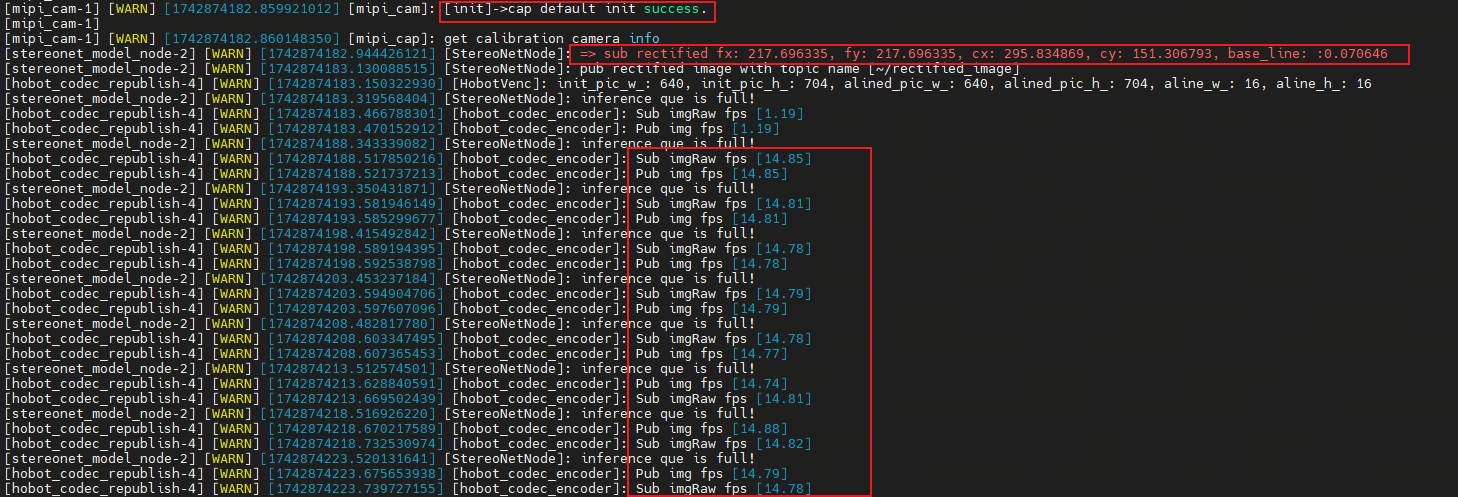
- Upon successful startup of the stereo algorithm, logs similar to the following will be printed.
fx/fy/cx/cy/baselineare the camera intrinsic parameters, andfpsindicates the algorithm's processing frame rate:
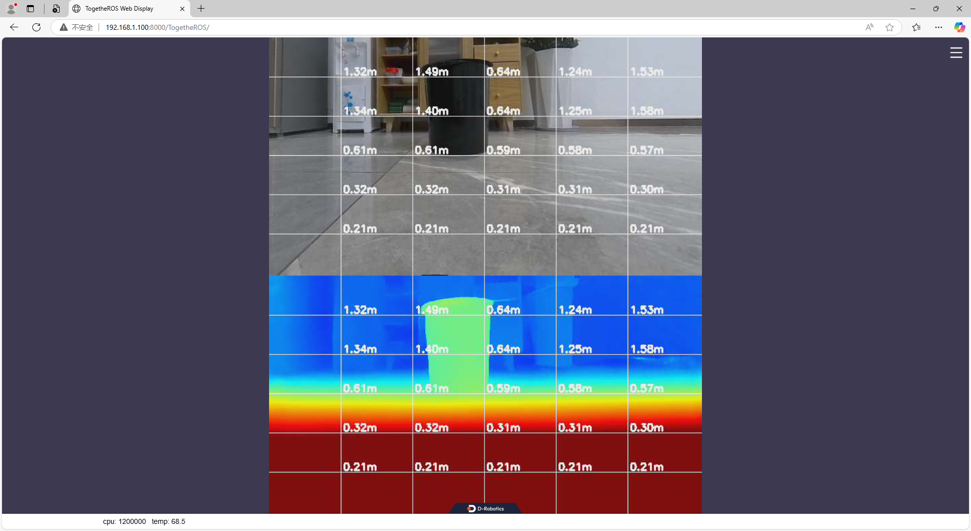
- View the RGB and depth images via the web interface by entering http://ip:8000 in your browser (the RDK IP in the figure is 192.168.1.100):
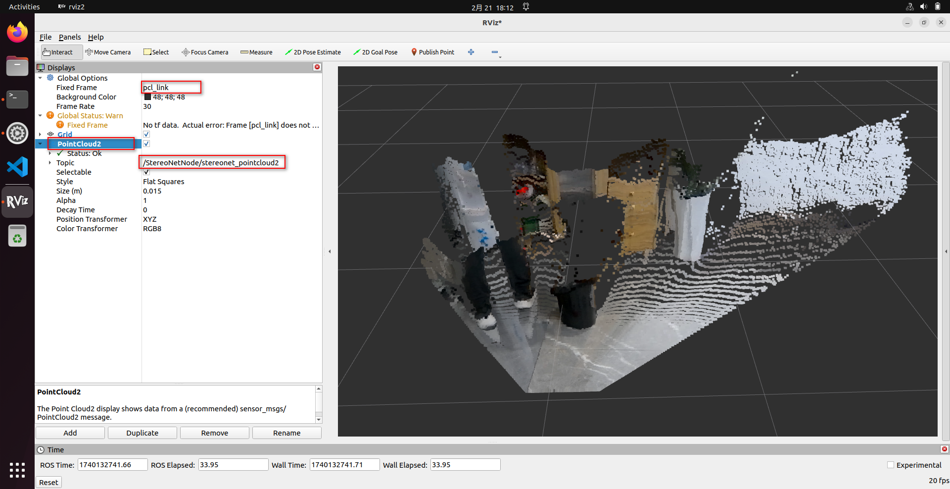
- View the point cloud using rviz2. rviz2 can be installed directly on the RDK. Note the following configuration is required in rviz2:
# Install rviz2
sudo apt install ros-humble-rviz2
# Launch rviz2
source /opt/tros/humble/setup.bash
rviz2
(5) Parameter Definitions
The run_stereo.sh script supports numerous configurable parameters. Below are definitions of some commonly used parameters; for other parameters, please refer to the comments in the source code:
-
stereonet_version: Controls which version of the algorithm to launch.
- For RDK X5, options include:
v2.0,v2.1,v2.2,v2.3,v2.4_int16,v2.4_int8,v2.5_int16,v2.5_int16_96,v2.5_int16_544_448,v2.5_int16_544_448_96 - For RDK S100, options include:
v2.1,v2.4,v2.4_1280_704
- For RDK X5, options include:
-
stereo_node_name: Specifies the ROS node name.
-
uncertainty_th: Confidence threshold. Only effective for models that output confidence and when set to a positive value. If enabled, it is recommended to set this to
0.10. -
stereo_image_topic / camera_info_topic: Names of the ROS topics the node subscribes to, for stereo images and corresponding camera info, respectively.
-
depth_image_topic / pointcloud2_topic / visual_image_topic: Control the names of topics published by the ROS node.
-
mipi_image_width, mipi_image_height, mipi_image_framerate: Control camera resolution and frame rate.
-
mipi_gdc_enable: Enables GDC correction in the camera. The camera reads calibration parameters from EEPROM to correct image distortion. All currently produced cameras include factory calibration parameters.
-
mipi_lpwm_enable: Enables hardware synchronization for the stereo camera, ensuring left and right images share identical timestamps. If set to
False, software synchronization is used, resulting in larger synchronization errors. -
mipi_rotation: Controls whether the image should be rotated. Currently, the CMOS sensor in the 132GS camera is mounted with a 90° rotation, so this parameter should be set to
90.0. -
mipi_channel, mipi_channel2: Used to swap the left/right image output order.
-
calib_method: Controls the rectification method.
- When
mipi_gdc_enable:=True, thehobot_mipi_campackage has already rectified the images, sohobot_stereonetdoes not need to perform additional rectification. In this case, setcalib_methodtonone. - When
mipi_gdc_enable:=Falseor the camera cannot perform image rectification, setcalib_methodtocustomand specifystereo_calib_file_path.
- When
-
stereo_calib_file_path: Specifies the path to custom stereo calibration parameters.
-
render_type: Controls the rendering mode. Default is
distance, which automatically generates pseudo-color depth visualizations based on depth for web display. Can also be set toindoororoutdoor. Setting toindooris not recommended. -
render_perf: Controls whether CPU/BPU utilization, latency, and FPS information are displayed on the rendered image. Options:
TrueorFalse. -
speckle_filter_enable: Enables/disables speckle filtering. Options:
TrueorFalse. -
max_speckle_size: Defines the maximum speckle size. Speckles smaller than this value will be filtered out. A larger value results in stronger filtering.
-
max_disp_diff: Defines the disparity difference threshold within a speckle. Pixels with disparity differences below this threshold are grouped into the same speckle. A smaller value results in stronger filtering.
-
pointcloud_height_min / pointcloud_height_max / pointcloud_depth_max: Control the point cloud display range (unit: meters).
-
pcl_filter_enable: Enables/disables point cloud filtering. Options:
TrueorFalse. -
grid_size: Grid size used during point cloud filtering (unit: meters).
-
grid_min_point_count: Minimum number of points required per grid cell during filtering. Grids with fewer points will be removed.
-
save_result_flag: Controls whether results are saved. If enabled, the following will be saved: camera parameters, original left/right images, rectified left/right images, disparity map, depth map, and point cloud.
-
save_dir: Specifies the save directory. The directory will be created automatically if it doesn't exist. Ensure sufficient disk space is available, otherwise saving will fail.
-
save_freq: Save frequency. For example, setting to
4means saving every 4 frames. -
save_total: Total number of frames to save.
-1means save indefinitely;100means stop after saving 100 frames. -
use_local_image_flag: Enables offline inference.
-
local_image_dir: Specifies the local image directory used during offline inference.
-
epipolar_mode: Enables epipolar alignment verification using a chessboard pattern.
-
epipolar_img: Specifies whether to use the
origin(original) orrect(rectified) images. -
chessboard_per_rows / chessboard_per_cols / chessboard_square_size: Define the number of inner corners per row/column and square size (in meters) of the chessboard.
-
feature_epipolar_mode: Controls whether to enable epipolar alignment detection based on ORB feature points.
-
infer_thread_num: Number of inference threads. Default is 2 threads, which yields higher FPS but higher latency. Setting to 1 reduces FPS slightly but also reduces latency.
-
stereonet_pub_web: Enables publishing visualization images to the web interface.
(6) Saving a Single Frame
- After successful program execution, open another terminal and run the following commands to save one frame of data:
source /opt/tros/humble/setup.bash

# First, check if the node is running properly. Note if ROS_DOMAIN_ID is set or the node name has been changed.
ros2 node list

# If the /StereoNetNode is running normally, execute the following to save one frame:
# Set the save directory (absolute path recommended; directory will be created if it doesn't exist)
ros2 param set /StereoNetNode save_dir /root/online_once
# Save one frame (can be executed repeatedly)
ros2 param set /StereoNetNode save_result_once true
(7) Saving Batch Data
- Method 1: Specify parameters at launch to enable saving
# With 230AI camera
bash run_stereo.sh --mipi_rotation 0.0 \
--save_result_flag True --save_dir /root/online_batch \
--save_freq 1 --save_total -1 \
--save_stereo_flag True --save_origin_flag False \
--save_disp_flag True --save_uncert_flag False \
--save_depth_flag True --save_visual_flag True \
--save_pcd_flag False

# With 132GS camera
bash run_stereo.sh \
--save_result_flag True --save_dir /root/online_batch \
--save_freq 1 --save_total -1 \
--save_stereo_flag True --save_origin_flag False \
--save_disp_flag True --save_uncert_flag False \
--save_depth_flag True --save_visual_flag True \
--save_pcd_flag False

# For S100, specify model version, e.g., add --stereonet_version v2.4
# save_stereo_flag    Save stereo images that are fed into the algorithm for inference
# save_origin_flag    Save original stereo images (not used directly by the algorithm; e.g., unrectified or mismatched resolution images that undergo preprocessing before inference)
# save_disp_flag      Save disparity map
# save_uncert_flag    Save uncertainty/confidence map (only supported by models that output confidence)
# save_depth_flag     Save depth map
# save_visual_flag    Save web-rendered visualization image
# save_pcd_flag       Save point cloud data
- Method 2: After successful program execution, open another terminal and run the following commands to save data:
source /opt/tros/humble/setup.bash

# First, check if the node is running properly. Note if ROS_DOMAIN_ID is set or the node name has been changed.
ros2 node list

# If /StereoNetNode is running normally, execute the following to configure saving:
# Set save directory (absolute path recommended; directory will be created if it doesn't exist)
ros2 param set /StereoNetNode save_dir /root/online_batch
# Set total number of frames to save
ros2 param set /StereoNetNode save_total 10
# Set save frequency
ros2 param set /StereoNetNode save_freq 1

# Configure what to save (set as needed)
ros2 param set /StereoNetNode save_stereo_flag true   # Save stereo images fed into the algorithm
ros2 param set /StereoNetNode save_origin_flag true   # Save original stereo images (preprocessed before inference)
ros2 param set /StereoNetNode save_disp_flag true     # Save disparity map
ros2 param set /StereoNetNode save_uncert_flag true   # Save confidence map (only for models supporting it)
ros2 param set /StereoNetNode save_depth_flag true    # Save depth map
ros2 param set /StereoNetNode save_visual_flag true   # Save web-rendered visualization
ros2 param set /StereoNetNode save_pcd_flag true      # Save point cloud data

# Start saving
ros2 param set /StereoNetNode save_result_flag true

# To save another batch after completion, re-execute the following:
# Reset total number of frames
ros2 param set /StereoNetNode save_total 10
# Start saving again
ros2 param set /StereoNetNode save_result_flag true
(8) Enabling Epipolar Alignment Verification Mode
If poor depth maps are observed, besides potential left/right image ordering issues, it may also indicate that the stereo images are not properly epipolar-aligned.
Stereo algorithms require high epipolar alignment accuracy—typically, the epipolar error should be less than 1 pixel.
This program implements two epipolar alignment verification methods:
-
Chessboard-based: More rigorous and recommended.
-
ORB feature-based: Does not require a calibration board; works in texture-rich scenes, but may yield larger epipolar errors.
-
Chessboard-based epipolar alignment verification command (example for X5 + 132GS camera):
# For X5 + 132GS camera (adjust parameters for S100 or other cameras as described above)
# Example uses a chessboard with 20 inner corners per row, 11 per column, and 0.06m square size
bash run_stereo.sh --epipolar_mode True \
--chessboard_per_rows 20 --chessboard_per_cols 11 --chessboard_square_size 0.06
Upon successful execution, the following image appears on the web interface:
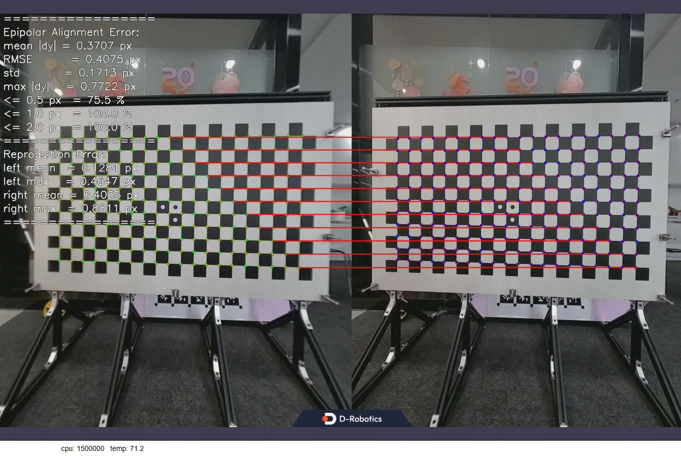
For chessboard-based verification, both epipolar error and reprojection error should be within 1 pixel for the stereo images to be considered valid; otherwise, the calibration parameters are incorrect.
- ORB feature-based epipolar alignment verification command (example for X5 + 132GS camera):
# For X5 + 132GS camera (adjust parameters for S100 or other cameras as described above)
bash run_stereo.sh --feature_epipolar_mode True
Upon successful execution, the following image appears on the web interface:
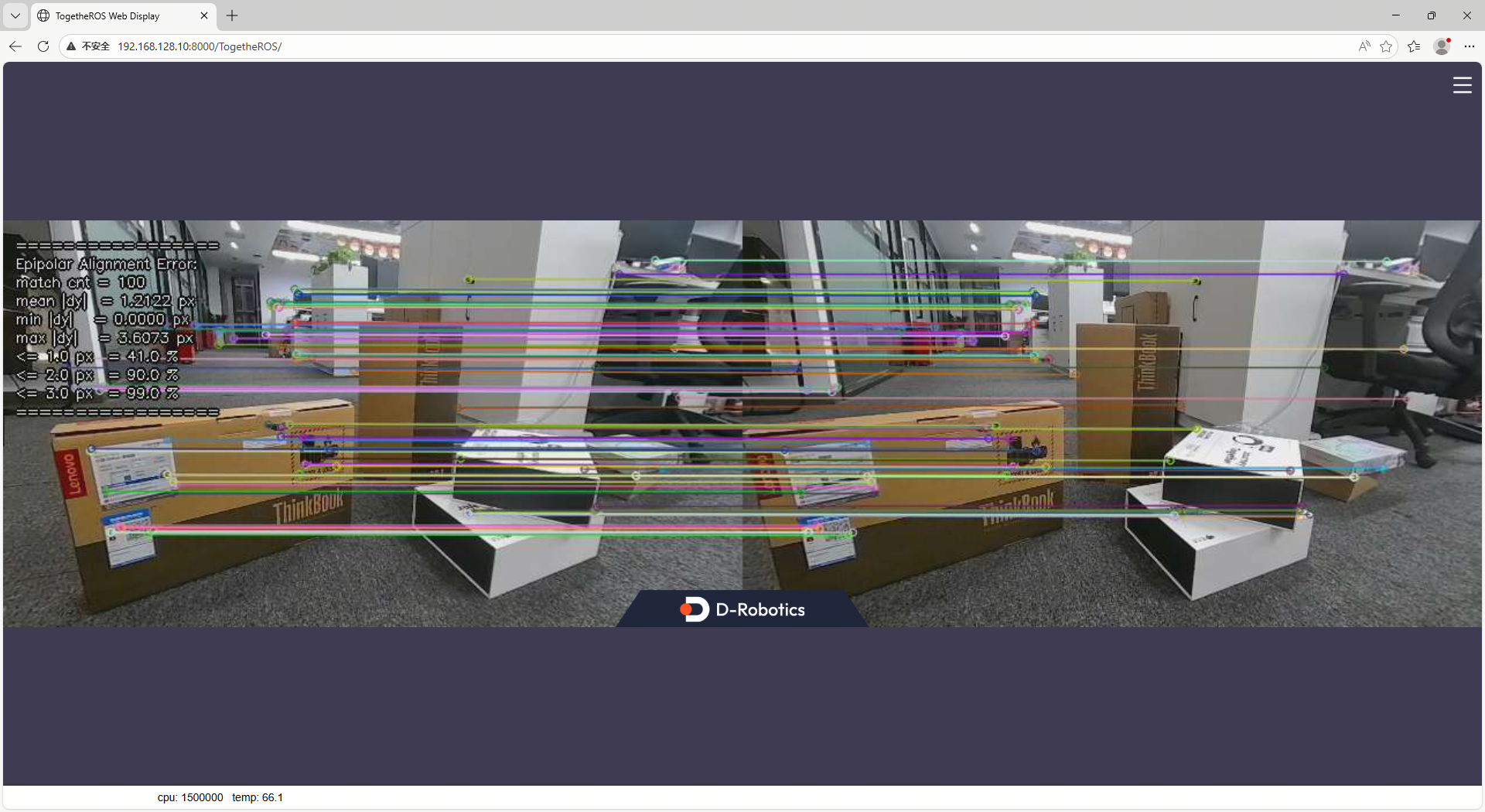
ORB-based verification is less strict. Empirically:
- For 640×352 resolution images, epipolar error should be < 1 pixel.
- For 1280×1088 resolution images, epipolar error should be < 2 pixels.
Only then are the stereo images considered acceptable.
5.4. Offline Launch Commands
(1) Preparing Offline Images
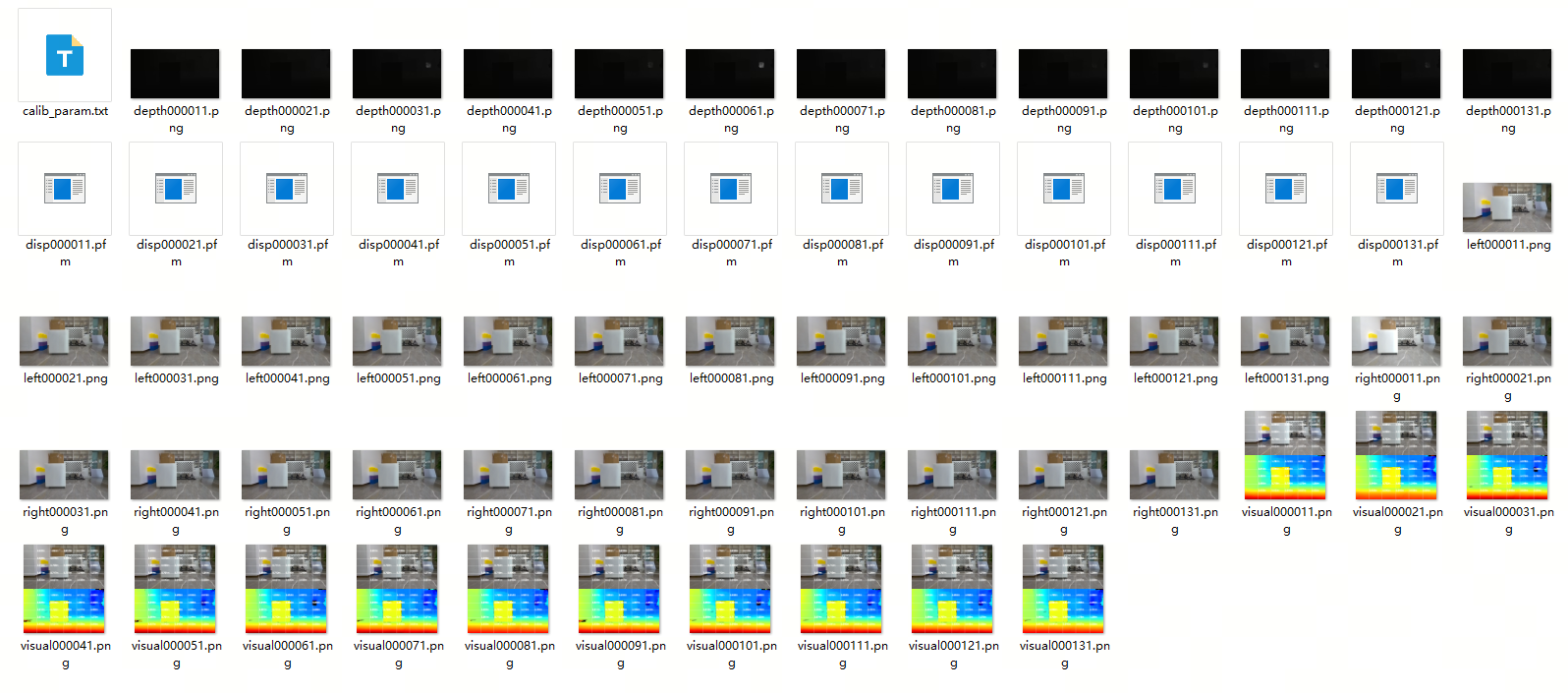
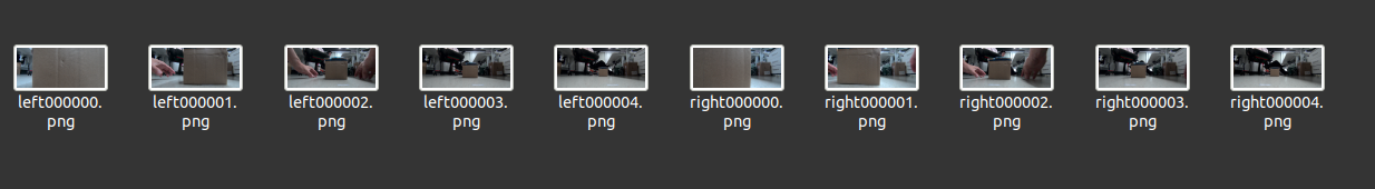
- To evaluate algorithm performance using local images, prepare and upload the following data to the RDK:
- Rectified and epipolar-aligned left/right images in PNG or JPG format. Images must follow a naming convention: left images must contain the word
left, and right images must containright. The algorithm processes images sequentially by index until all are processed:
- Camera intrinsic parameters file, saved in the image directory as
camera_intrinsic.txt. Example content:
# fx fy cx cy baseline(m)
215.762581 215.762581 325.490113 173.881556 0.079957
(2) Execute the startup command
- Connect to the RDK via SSH and run the following command:
- RDK X5
- RDK S100
bash run_stereo.sh \
--use_local_image_flag True --local_image_dir <offline image path> \
--save_result_flag True --save_dir <result save path> \
--save_stereo_flag True --save_origin_flag False \
--save_disp_flag True --save_uncert_flag False \
--save_depth_flag True --save_visual_flag True \
--save_pcd_flag True

# If the web interface displays images too quickly, add the following parameter to control the pause duration: --image_sleep 2000
bash run_stereo.sh --stereonet_version v2.4 \
--use_local_image_flag True --local_image_dir <offline image path> \
--save_result_flag True --save_dir <result save path> \
--save_stereo_flag True --save_origin_flag False \
--save_disp_flag True --save_uncert_flag False \
--save_depth_flag True --save_visual_flag True \
--save_pcd_flag True

# If the web interface displays images too quickly, add the following parameter to control the pause duration: --image_sleep 2000
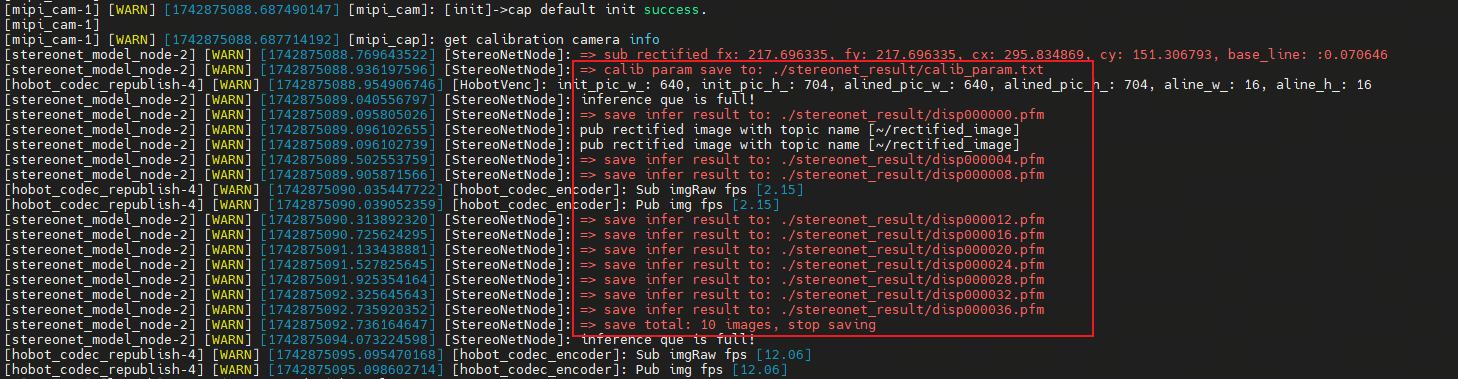
- Upon successful execution, the following log will be printed:
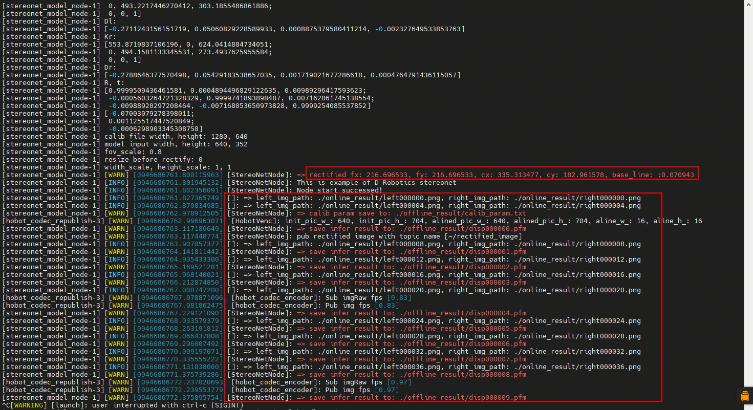
- View RGB and depth images via the web interface by entering http://ip:8000 in your browser (the RDK IP shown in the figure is 192.168.128.10):

5.5. Running with ZED Camera
(1) ZED Camera Installation
- The ZED stereo camera is shown below:
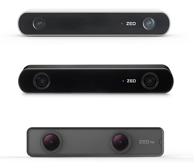
- Simply connect the ZED camera to the RDK via USB.
(2) Startup Commands
- First, launch the ZED camera. Connect to the RDK via SSH and run the same command for both X5 and S100:
source /opt/tros/humble/setup.bash

ros2 launch hobot_zed_cam zed_cam_node.launch.py \
resolution:=720p \
need_rectify:=true dst_width:=640 dst_height:=352
Parameter explanations:
| Parameter | Description |
|---|---|
| resolution | Original ZED output resolution (with distortion). 720p means 1280×720; can also be set to 1080p. |
| need_rectify | Indicates whether the final output images require rectification. |
| dst_width | Final rectified output image width: 640 |
| dst_height | Final rectified output image height: 352 |
Note: The RDK must be connected to the internet when running the ZED camera, as ZED needs to download calibration files online.
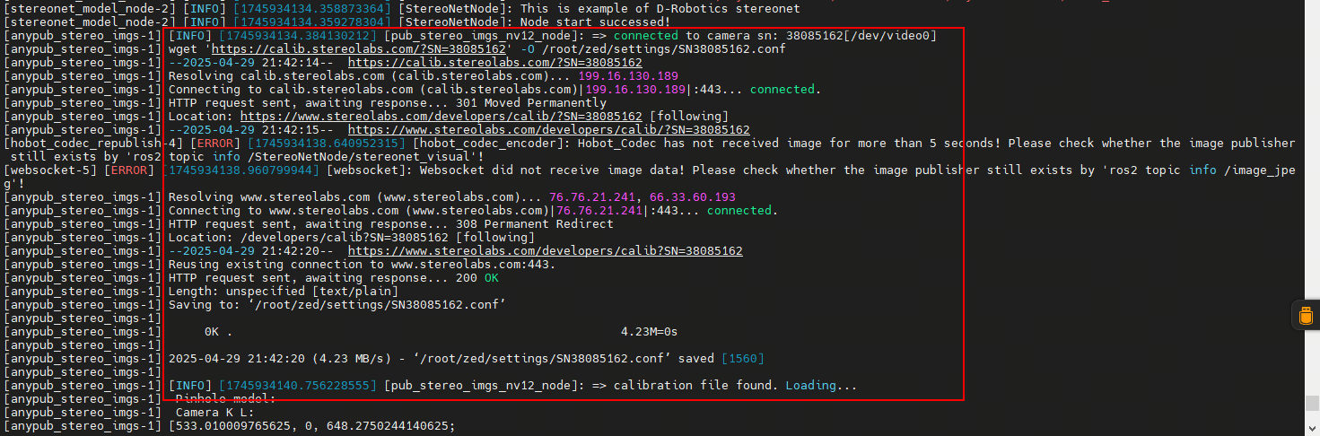
With internet access, the program will automatically download the calibration file. If the RDK is offline, you can manually download the calibration file and upload it to the RDK.
According to the log message, open a browser on your PC and navigate to (https://calib.stereolabs.com/?SN=38085162) to download the calibration file SN38085162.conf.
Note that each ZED camera has a unique SN code. When using your own device, please download the corresponding calibration file based on the error message, and upload it to the /root/zed/settings/ directory. Create this directory manually if it doesn't exist.
- Next, launch the stereo algorithm by opening another terminal and executing:
bash run_stereo.sh --use_mipi_cam False --camera_info_topic /image_combine_raw/camera_info
- View the depth map via the web interface by entering http://ip:8000 in your browser (replace "ip" with the actual IP address of your RDK). For instructions on viewing point clouds and saving images, please refer to the relevant settings described above.
6. Topic Description of the Function Package
6.1. Subscribed Topics
| Default Name (adjustable via parameters) | Message Type | Description |
|---|---|---|
| /image_combine_raw | sensor_msgs::msg::Image | Vertically stacked left-right images used for model inference |
| /image_combine_raw/right/camera_info (optional) | sensor_msgs::msg::CameraInfo | Camera calibration parameters for disparity-depth conversion |
6.2. Published Topics
| Default Name (adjustable via parameters) | Message Type | Description |
|---|---|---|
| /StereoNetNode/stereonet_depth | sensor_msgs::msg::Image | Depth image (unit: millimeters) |
| /StereoNetNode/stereonet_visual | sensor_msgs::msg::Image | Visualized rendered image |
| /StereoNetNode/stereonet_pointcloud2 | sensor_msgs::msg::PointCloud2 | Point cloud (unit: meters) |
| /StereoNetNode/rectify_left_image | sensor_msgs::msg::Image | Rectified left image (algorithm input) |
| /StereoNetNode/rectify_right_image | sensor_msgs::msg::Image | Rectified right image (algorithm input) |
| /StereoNetNode/origin_left_image | sensor_msgs::msg::Image | Original left image (not fed into algorithm) |
| /StereoNetNode/origin_right_image | sensor_msgs::msg::Image | Original right image (not fed into algorithm) |