Multi-Camera and Synchronization with Lidar
Overview
In multi-camera deployment scenarios, synchronization across multiple cameras is typically required to meet algorithmic or application needs. Additionally, synchronization with Lidar is often necessary, which can be achieved via methods such as ETH PPS.
On the S100 platform, the LPWM module is primarily used for camera triggering. It can generate PWM waveforms with configurable delay outputs to calibrate sensor exposure synchronization. Furthermore, it supports multiple external trigger sources, enabling time synchronization with MCU or GPS devices.
This document focuses on the fundamental capabilities of the LPWM module, explaining its working principles and usage methods, and provides typical synchronization solutions for multi-camera and Lidar scenarios for reference in practical projects.
This document describes only one recommended hardware connection scheme for camera and Lidar synchronization. If other hardware configurations are used, users can adapt the configuration methods described herein accordingly.
Hardware Pathways
LPWM Module
The S100 platform features a total of 3 LPWM chips, each containing 4 LPWM channels. Please configure according to your actual hardware connections.
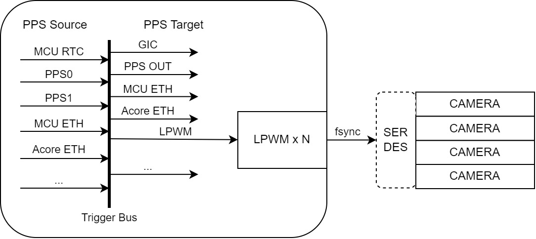
The core implementation of camera synchronization on the S100 relies on the LPWM module. It supports various trigger signal sources on the S100 and generates multi-channel configurable PWM signals, which are output to external cameras (optionally forwarded via SerDes), thereby achieving synchronization between the trigger source and cameras, as well as inter-camera synchronization.
Key considerations when using the LPWM include:
- The actual hardware-connected channels in use.
- Selection of the LPWM synchronization trigger source: supports MCU RTC/PPS0/PPS1/ETH PPS0/ETH PPS1/MCU ETH PPS, etc.
- Offset configuration of the LPWM relative to the synchronization trigger source: must be adapted according to frame rate requirements, PPS period, phase requirements, etc.
- Target signal waveform parameters of the LPWM: period, duty_time, etc.
- LPWM advanced features: slow synchronization threshold, adjust_step configuration.
For more details on LPWM module functionality and usage, please refer to: [LPWM Usage]
LPWM Synchronization Sources
LPWM operating principle: The LPWM is triggered by a PPS signal and acts as a Target-side device on the Trigger Bus. Each LPWM device can independently select its trigger source.
The process of transmitting the PPS signal to the camera trigger (cam-trig) is illustrated below. The PPS trigger connects to the LPWM module, which then outputs a signal to the camera:
For more information on PPS synchronization sources, please refer to: PPS Description
Important notes regarding LPWM trigger source usage:
- Multiple external trigger sources are mutually exclusive; only one can be selected per LPWM module.
- Different LPWM modules can be synchronized by selecting the same external trigger source.
- Different channels within the same LPWM module share the same trigger source but can be configured with different offset/period/duty parameters.
Multi-Camera Synchronization Connection
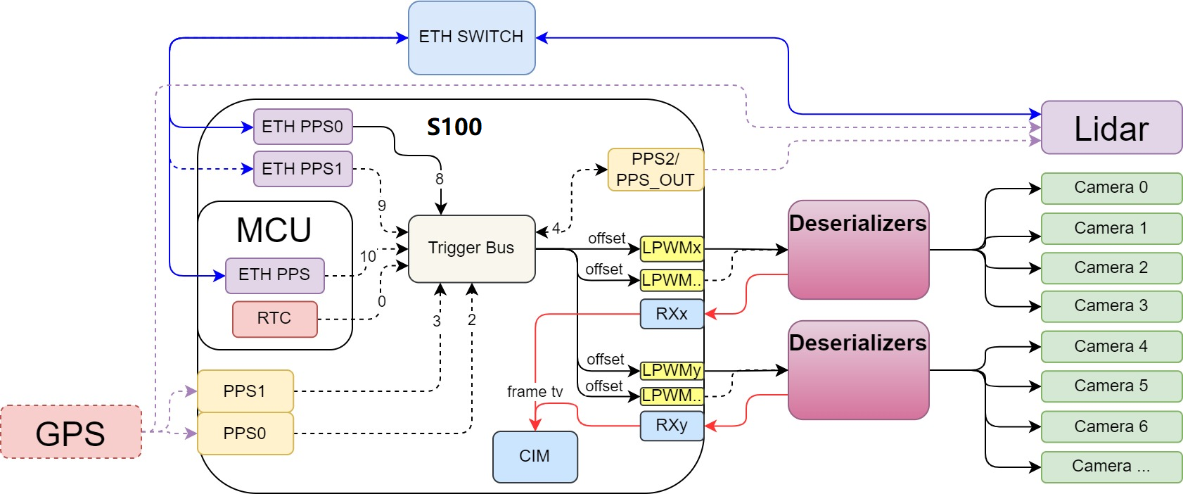
For single-S100 camera deployment scenarios, the typical connection diagram is as follows:
Key points:
- The S100 trigger source can originate from an external GPS device or network-based ETH PPS.
- Synchronization can also be achieved between the MCU and S100.
- Different LPWMs within the same S100 can select the same synchronization source.
- Different DES (Deserializer) units can connect to different LPWM channels.
- SerDes can transparently transmit LPWM signals to the sensor side via the reverse channel on the Link cable, connecting to FSYNC for synchronization triggering.
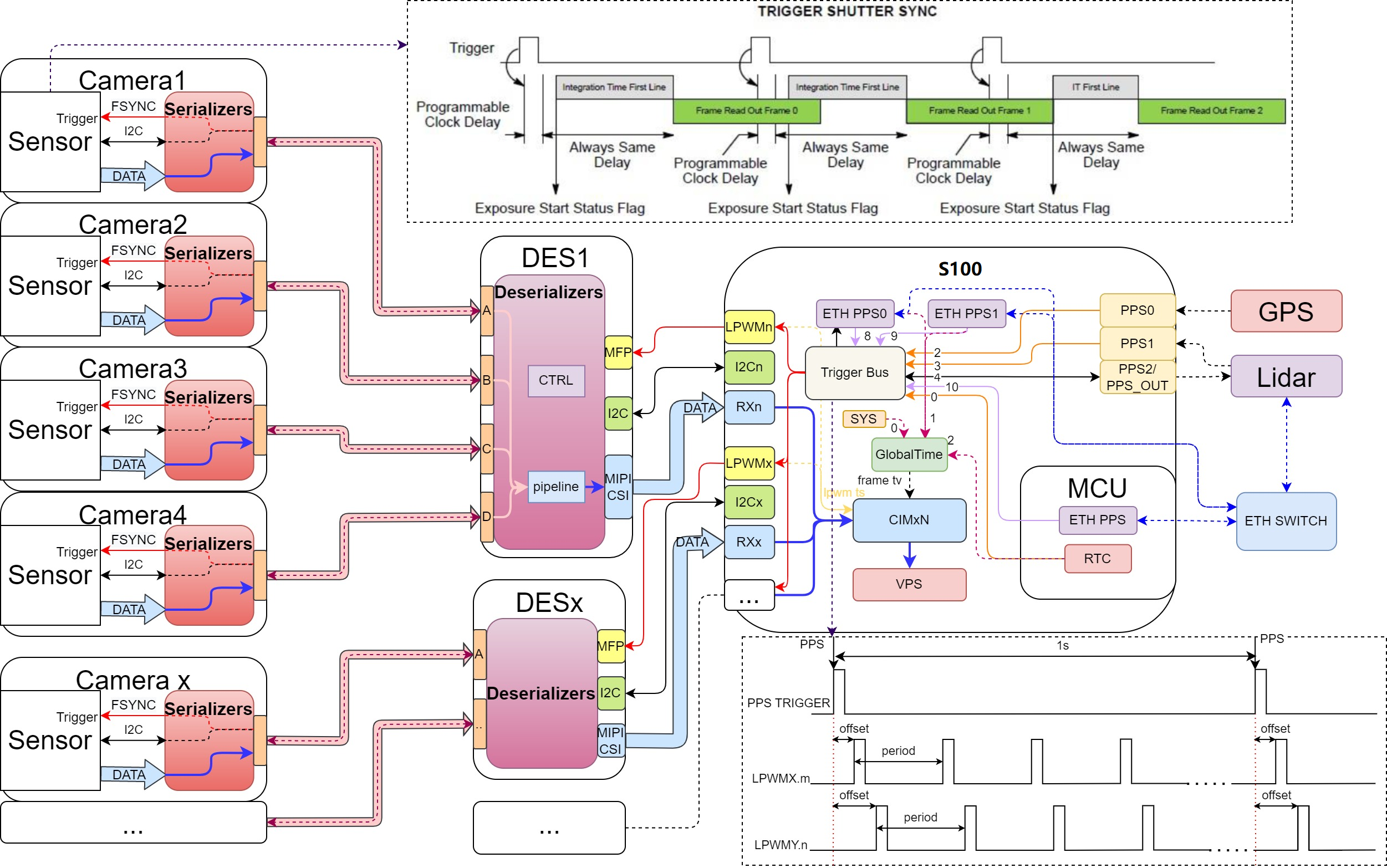
Integration with Lidar
In scenarios involving Lidar, the following connection scheme can be used:
Key points:
- The S100 trigger source can come from an external GPS device or via network time synchronization methods.
- The Lidar device can align its clock with the S100 using time synchronization protocols (e.g., gPTP).
- Camera synchronization is achieved by triggering the DES via S100’s LPWM output, which then distributes the signal to individual cameras to synchronize exposure/image capture.
- When camera data enters the S100’s CIM module, a timestamp is recorded at the Frame Start moment to mark the frame time.
Software Solution
Camera and Lidar Time Alignment Requirements
In scenarios requiring simultaneous use and synchronization of cameras and Lidar, typical functional requirements include:
- Time synchronization between Lidar and S100, ensuring both operate on the same time axis.
- Lidar performs periodic scans based on synchronized time—for example, at 10Hz (100ms period), starting scans precisely at every 100ms interval.
- Cameras use LPWM triggered by the synchronized PPS signal to initiate exposure/readout for each frame, aligning with Lidar scan timing—for example, at 30fps.
- Timestamps of camera image data and Lidar data must reside on the same time axis with a defined alignment relationship to enable sensor fusion.
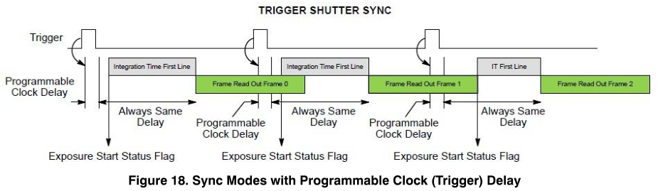
The desired time alignment objective is illustrated below:
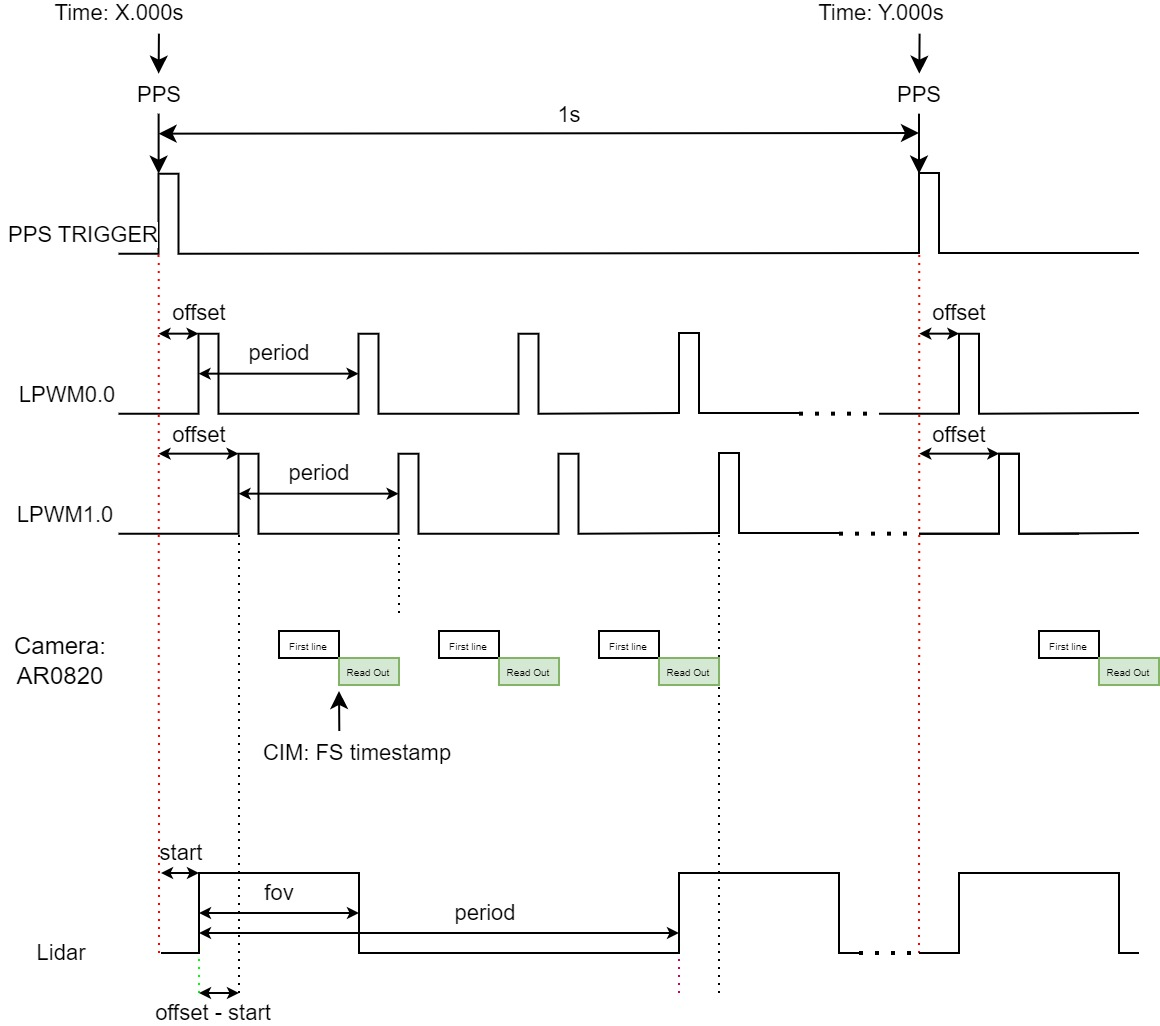
At the exact PPS second boundary: LPWM output triggers exposure (if offset is set to 0), and Lidar starts scanning (if start delay is 0).
This software solution adapts to the solid-line hardware connections shown in the diagram above:
- Both S100 and Lidar connect to a network switch, enabling time synchronization over the network.
- Lidar scans at 10Hz, initiating scans precisely at every 100ms mark, with aligned timestamps on its data.
- Multiple cameras connect to the S100 via SerDes and also receive LPWM signals for exposure synchronization triggering.
- The LPWM trigger source uses Acore’s ETH PPS0.
LPWM Trigger Source Selection
The LPWM module supports multiple trigger sources. For the hardware connection described above, several options remain available; please refer to: [Recommended LPWM Configuration].
In this solution, Acore ETH PPS0 is used as the LPWM trigger source because:
- Both Lidar and S100 use network-based synchronization, allowing PHC time to serve as a unified time axis.
- Acore ETH PPS exhibits the smallest timing error and is therefore recommended as the primary choice.
When using Acore ETH PPS0 in fixed mode, its rising edge has a fixed offset of 536.871ms relative to the PPS second boundary. This offset must be accounted for during configuration. For more details, please refer to: Acore ETH PPS Description
Camera Synchronization Mode Selection
Sensor exposure output typically operates in either Master mode (autonomous exposure based on configuration; frames are output automatically once streaming starts) or Slave mode (exposure triggered externally; output occurs only after receiving a trigger). By default, Master mode is used, but Slave mode is required for synchronized output.
Below is an example using the AR0820 module to illustrate Slave mode:
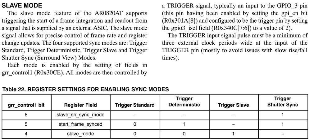
Within Slave mode, multiple synchronization methods exist. The commonly used "shutter sync" mode ensures that images are output at a fixed time after the trigger (guaranteeing Frame Start timestamp alignment) and does not drop incoming trigger signals (i.e., triggers arriving during image output are not ignored).
Configuration examples:
// See: source/hobot-camera/drivers/sensor/ar0820/inc/ar0820_setting.h
uint16_t ar0820_trigger_standard_setting[] = {
    //0x301A, 0x0058, // RESET_REGISTER_RESET,RESET_REGISTER_STDBY_EOF
    0x301A, 0x0958, // RESET_REGISTER_GPI_EN, FORCED_PLL_ON
    0x31C6, 0x2000, // MASK_FRAMER_STANDBY
    0x30B0, 0x8100, // PIXCLK_ON
    0x30CE, 0x0000, // TRIGGER STANDARD MODE
    0x30CE, 0x0000, // TRIGGER STANDARD MODE
};
uint16_t ar0820_trigger_shutter_sync_setting[] = {
    //0x301A, 0x0058, // RESET_REGISTER_RESET,RESET_REGISTER_STDBY_EOF
    0x301A, 0x095C, // RESET_REGISTER_GPI_EN, FORCED_PLL_ON, STREAM
    0x31C6, 0x2000, // MASK_FRAMER_STANDBY
    0x30B0, 0x8100, // PIXCLK_ON
    0x30CE, 0x0120, // TRIGGER SHUTTER SYNC MODE
    0x30CE, 0x0120, // TRIGGER SHUTTER SYNC MODE
};
uint16_t ar0820_trigger_gpio_setting[][8] = {
    {
        0x340A, 0x00EE, // GPIO0_INPUT_ENABLE
        0x340A, 0x00EE, // GPIO0_INPUT_ENABLE
        0x340C, 0x0002, // GPIO_ISEL
        0x340E, 0x2100, // GPIO_OSEL
    },
    {
        0x340A, 0x00DD, // GPIO1_INPUT_ENABLE
        0x340A, 0x00DD, // GPIO1_INPUT_ENABLE
        0x340C, 0x0008, // GPIO_ISEL
        0x340E, 0x2100, // GPIO_OSEL
    },
    {
        0x340A, 0x00BB, // GPIO2_INPUT_ENABLE
        0x340A, 0x00BB, // GPIO2_INPUT_ENABLE
        0x340C, 0x0020, // GPIO_ISEL
        0x340E, 0x2010, // GPIO_OSEL
    },
    {
        0x340A, 0x0077, // GPIO3_INPUT_ENABLE
        0x340A, 0x0077, // GPIO3_INPUT_ENABLE
        0x340C, 0x0080, // GPIO_ISEL
        0x340E, 0x0210, // GPIO_OSEL
    },
};
In practice, enable synchronization functionality according to the config_index (requires corresponding implementation in the sensor library).
The above is only an example for AR0820; other cameras are similar. The camera synchronization function mainly requires the following configurations:
Slave mode: Configure the module's SYNC mode according to actual requirements.
FSYNC selection: Choose an appropriate GPIO as the FSYNC signal based on the module's actual hardware connections. Some modules include an ISP, in which case you only need to configure FSYNC and do not need to set the sensor to Slave mode.
Regarding the FSYNC signal output of the camera, different modules may exhibit different characteristics, such as:
-
The FSYNC signal is only used to align exposure output and cannot control frame rate; therefore, the LPWM period must be set to match the actual frame rate.
-
The module might operate in pure Slave mode, where no frames are output without an FSYNC signal, or it might only use FSYNC for alignment, meaning frames are still output even without FSYNC.
-
Pay attention to the choice of synchronization mode: is it exposure synchronization or frame output synchronization?
-
In exposure synchronization, exposure starts simultaneously across cameras. After exposure completes, frames are read out and output immediately. Since output timing depends on exposure duration, timestamps might not be perfectly aligned.
-
In frame output synchronization, frames are read out and output simultaneously at a specified moment after exposure, ensuring consistent timestamps. This solution uses frame output synchronization.
-
Different modules may have different exposure times, so timestamps after synchronization might still vary slightly.
Recommended Solution
Camera and LiDAR Synchronization Alignment Scheme
Based on the aforementioned hardware connections and software approach, the synchronization scheme is as follows:
-
Use Acore ETH PPS0 as the trigger source.
-
LiDAR begins scanning precisely at every full hundred milliseconds (e.g., 100ms, 200ms, etc.), and its data carries aligned timestamps.
-
The camera (using AR0820 as an example) employs SHUTTER SYNC for frame output synchronization with auto-exposure enabled.
-
Adjust the LPWM offset to align the phase to full hundred milliseconds. For example, at 30 fps, set offset = 463.129 ms; taking modulo 33.333 ms yields 29.8 ms.
-
After correctly configuring the LPWM offset, the camera can synchronize its output precisely at every full hundred milliseconds (every 3 frames), aligning with LiDAR data.
Camera Configuration
The following is the synchronization configuration for a single AR0820 channel:
{
             "deserial_0": {
             "deserial_name": "max96712",
             "deserial_addr": "0x29",
             "deserial_gpio": {
                     "camerr_pin": [4, 6, 8, 10],
                     "trig_pin": [5]
             },
             "poc": {
                     "poc_addr": "0x28",
                     "poc_map": "0x1320"
             }
     },
             "port_0": {
             "sensor_name": "ar0820std",
             "serial_addr": "0x41",
             "sensor_addr": "0x11",
             "eeprom_addr": "0x51",
             "sensor_mode": 5,
             "fps": 30,
             "width": 3840,
             "height": 2160,
             "extra_mode": 5,
             "config_index": 512,
             "deserial_index": 0,
             "deserial_port": 0
     }
}
Synchronization is primarily enabled by setting bit 9 (+512) in config_index:
{
    "config_0":{
        "port_0":{
            "config_index":512,
        },
    }
}
The trig_pin under deserial configures the MFP index corresponding to the LPWM hardware connection. This requires support from the deserializer library and must also be configured in the JSON as follows:
"deserial_gpio": {
        "trig_pin": [5]
},
-
If one LPWM channel triggers multiple cameras simultaneously, configure only one index value (e.g., MFP5:
[5]). -
If multiple LPWM channels trigger different cameras separately, configure multiple index values corresponding to multiple links (e.g., MFP5 for Link A and MFP14 for Link B:
[5,14]).
Trigger Configuration
LPWM configuration is performed via JSON. Below is a configuration example; for more details, refer to: [LPWM JSON Configuration]
{
    "lpwm_chn0": {
        "trigger_source": 8,
        "trigger_mode": 1,
        "period": 33333,
        "offset": 29800,
        "duty_time": 100,
        "threshold": 0,
        "adjust_step": 0
    },
    "lpwm_chn1": {
        "trigger_source": 8,
        "trigger_mode": 1,
        "period": 33333,
        "offset": 29800,
        "duty_time": 100,
        "threshold": 0,
        "adjust_step": 0
    },
    "lpwm_chn2": {
        "trigger_source": 8,
        "trigger_mode": 1,
        "period": 33333,
        "offset": 29800,
        "duty_time": 100,
        "threshold": 0,
        "adjust_step": 0
    },
    "lpwm_chn3": {
        "trigger_source": 8,
        "trigger_mode": 1,
        "period": 33333,
        "offset": 29800,
        "duty_time": 100,
        "threshold": 0,
        "adjust_step": 0
    }
}
When trigger_mode is set to 1 and trigger_source is set to 8, ETH PPS0 is used as the synchronization source.
Summary
Multi-camera synchronization on the S100 platform is achieved through coordinated hardware connections and software configuration of the LPWM module.
During hardware design, considerations must include varying frame rate requirements, synchronization needs of different camera modules, and selection of external trigger signals.
When bringing up and configuring camera modules, ensure LPWM synchronization passthrough is properly set up over SerDes, configure the sensor in Slave mode, and select an appropriate GPIO as the FSYNC signal to enable synchronized triggering and output.
In LiDAR-camera synchronization scenarios, use ETH PPS0 as the sync source with fixed mode, and correctly calculate and configure the LPWM offset to achieve precise phase alignment.