Camera Bring-up
HBN Sensor Bring-up
Scope
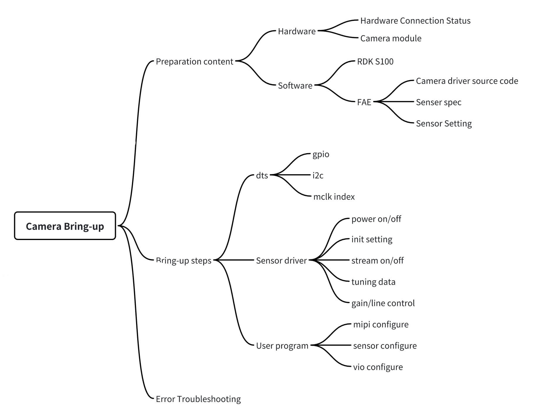
This section provides an overview of the RDK-S100 camera bring-up process, helping readers quickly understand and master the RDK-S100 camera framework, how to rapidly add new camera configurations, and successfully bring up the camera.
This documentation uses the RDK-S100 development board with an imx219 camera module as an example for configuration instructions. For other hardware platforms or camera modules, please refer to actual hardware specifications.
Preparation
Hardware resources: RDK-S100 development board, camera module.
Software resources: System SDK, camera driver source code, sensor datasheet, sensor initialization settings, etc.
The camera-related hardware resources of the RDK-S100 development board are listed below:
| RDK-S100 | MIPI host | I2C | gpio_en | gpio_lpwm_mclk | Others |
|---|---|---|---|---|---|
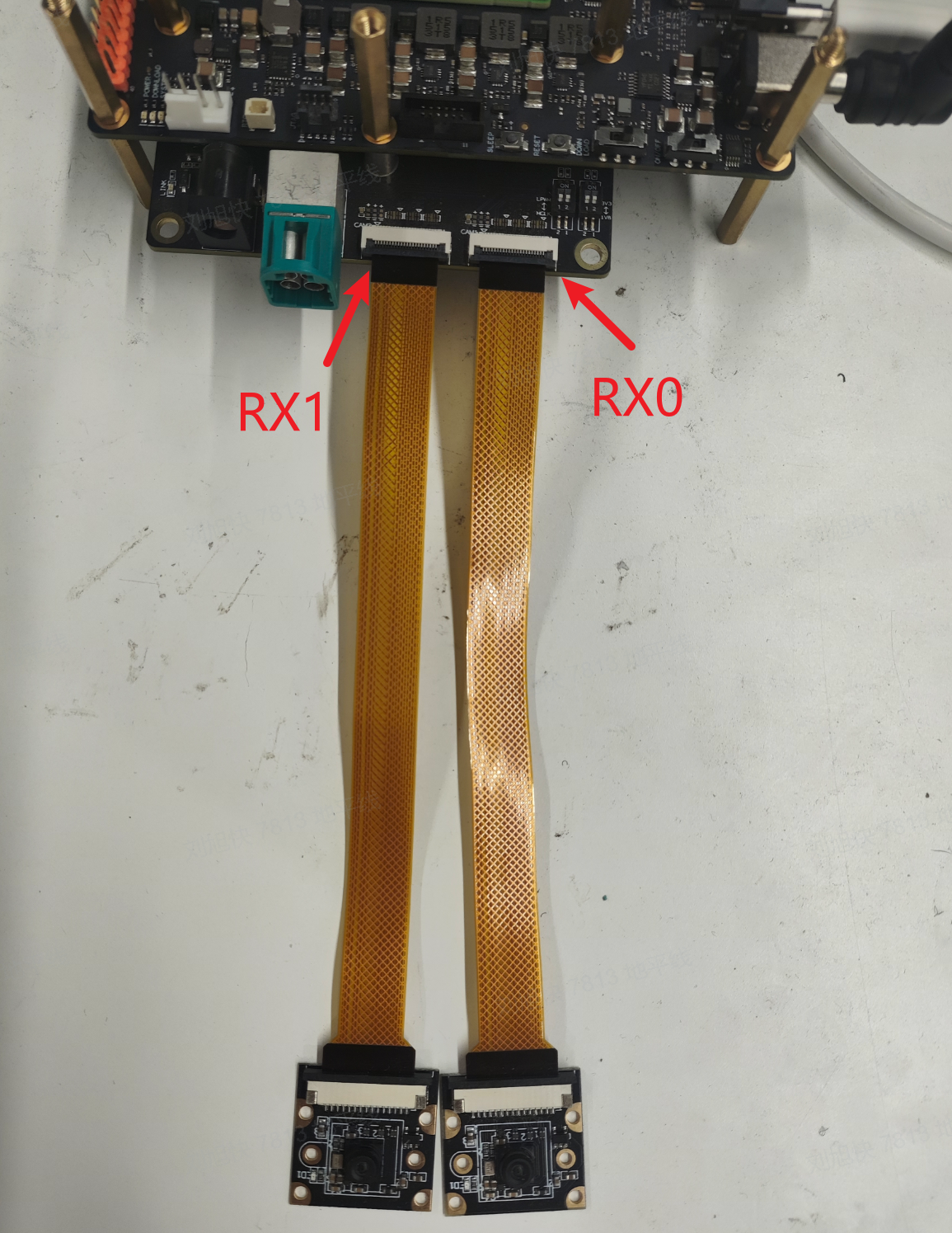
| RX0 Supports imx219 module | 0 4 lane | 1 | SPI1_CSN0 gpio_number:502 | Selectable via DIP switch • LPWM0_DOUT0 gpio_number:456 • mclk 24MHz | Note: The imx219 module has an external 24MHz crystal oscillator, so SOC-side mclk output is not required |
| RX1 Supports imx219 module | 1 4 lane | 2 | SD_WPROT gpio_number:494 | Selectable via DIP switch • LPWM0_DOUT1 gpio_number:457 • mclk 24MHz | Note: The imx219 module has an external 24MHz crystal oscillator, so SOC-side mclk output is not required |
| RX4 For SerDes connection | 4 4 lane | 3 | Not specified | Not specified | Deserializer max96712, addr: 0x29; PoC max20087, addr: 0x28 |
Hardware connection diagram:
Steps to Add and Bring Up a New Sensor
When adapting new hardware and a new camera to the RDK-S100 platform, you only need to modify the platform device tree (DTS), camera driver library, and related configuration files. System libraries generally do not require modification.
DTS Modifications
Sensor GPIO Configuration
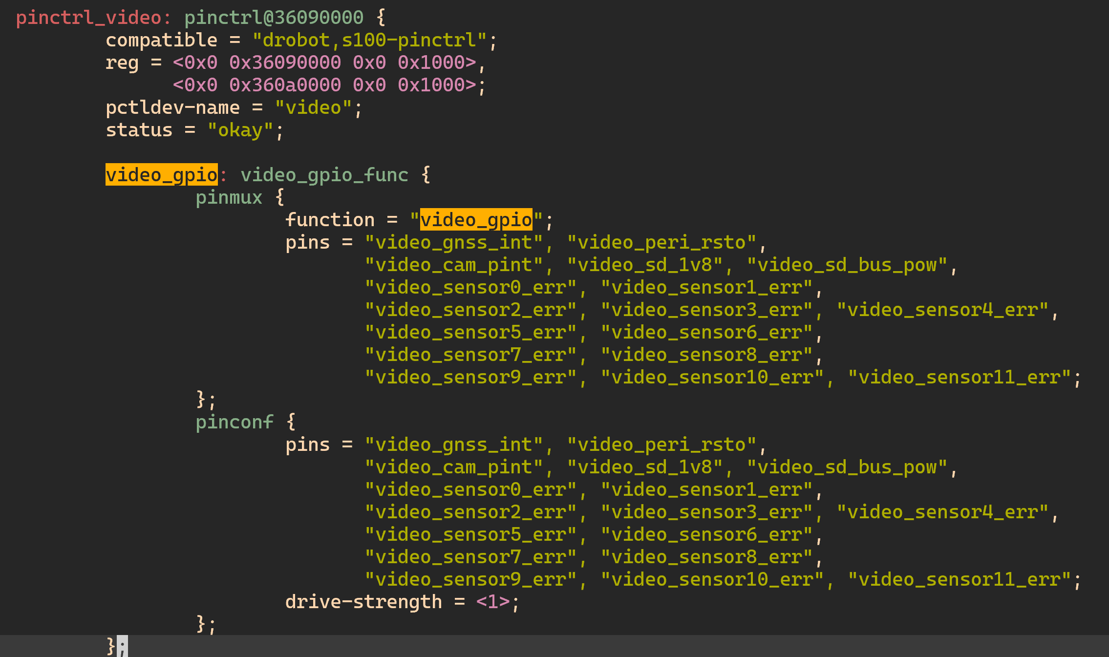
Ensure that the GPIOs used by the new sensor hardware are configured in the drobot-s100-pinctrl.dtsi --> pinctrl_video --> video_gpio node. This ensures the system configures the corresponding pins as GPIOs during boot-up, allowing user programs to control them.
vcon is the RDK-S100 camera DTS node used to manage sensor hardware. If the sensor requires specific timing signals to start correctly, the corresponding GPIOs must be configured in this node. Configure these settings according to your actual hardware connections; relevant information can be obtained from schematics and pin lists.
// DTS: Set GPIOs in the corresponding vcon node. Note that vcon port numbers correspond one-to-one with MIPI RX ports:
// vcon0 -- RX0
// ....
// vcon3 -- RX3
&vin_vcon0 {
        bus = <2>;
        gpio_poc = <0>;
        gpio_des = <0>;
        sensor_err = <0>;
        //gpio_oth = <444 445>; // Not needed for imx219, so commented out and left empty
        lpwm_chn = <0 1 2 3>;
        rx_phy = <2 0>;
};
Sensor I2C Configuration
The I2C bus number must be bound to the MIPI RX port in the DTS vcon node. Configure this according to your actual hardware connections; relevant information can be obtained from schematics.
// Set I2C bus in the corresponding vcon node; for example, RX0 uses I2C2
&vin_vcon0 {
        bus = <2>;
        gpio_poc = <0>;
        gpio_des = <0>;
        sensor_err = <0>;
        lpwm_chn = <0 1 2 3>;
        rx_phy = <2 0>;
};
MCLK Configuration
The RDK-S100 baseboard hardware currently does not support SOC-generated MCLK signals connected directly to the sensor module. Only modules with external crystal oscillators are supported.
DTS Modification Verification
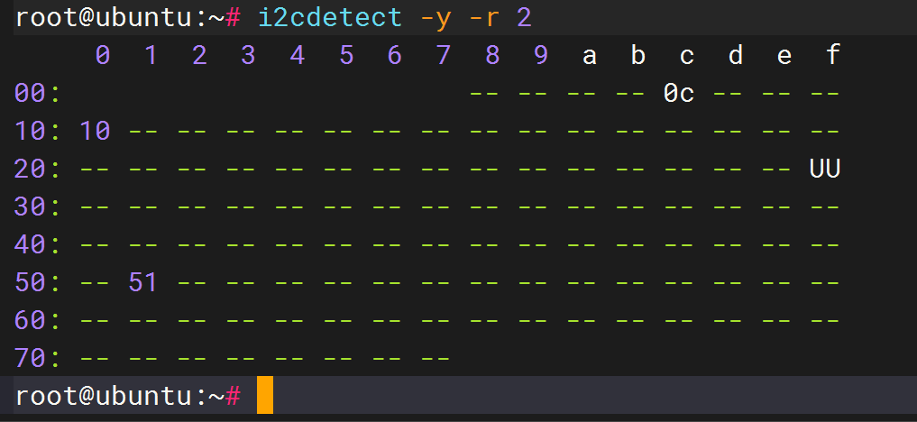
If the DTS configuration is correct and the hardware is properly connected—with proper sensor power supply and MCLK—you should be able to detect the sensor’s I2C address using i2cdetect.
Use the echo command to control sensor power-on or reset (note: for the imx219 module, GPIO operations are not required):
echo 502 > /sys/class/gpio/export
echo out > /sys/class/gpio/gpio502/direction
echo 1 > /sys/class/gpio/gpio502/value
echo 502 > /sys/class/gpio/unexport
Use i2cdetect to scan for the sensor’s I2C address. If the correct address appears as shown below, the DTS configuration is correct; otherwise, review your DTS settings.
 | 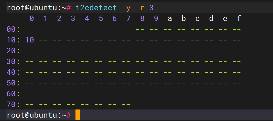 |
|---|
Adding Sensor Driver Files
Sensors from different manufacturers come with varying driver styles and settings. Therefore, you must convert the original sensor driver into RDK-S100-compatible camera driver code, compile it into a shared library (.so), and copy it to /usr/hobot/lib/sensor/ on the device. Note: Before MIPI starts, ensure the sensor stream is not active.
The system SDK includes a sensor driver template file (imx219_utility.c) and adapted drivers for other sensors under hobot-camera/drivers/sensor/. When adding support for a new camera sensor, refer to and modify these files accordingly.
 #ifdef CAMERA_FRAMEWORK_HBN
 SENSOR_MODULE_F(imx219, CAM_MODULE_FLAG_A16D8);
 sensor_module_t imx219 = {
         .module = SENSOR_MNAME(imx219),
 #else
 sensor_module_t imx219 = {
         .module = "imx219",
 #endif
         .init = sensor_init,
         .start = sensor_start,
         .stop = sensor_stop,
         .deinit = sensor_deinit,
         .aexp_gain_control = sensor_aexp_gain_control,
         .aexp_line_control = sensor_aexp_line_control,
         .power_on = sensor_poweron,
         .power_off = sensor_poweroff,
         .userspace_control = sensor_userspace_control,
 };
As shown above, the sensor driver interface in the RDK-S100 camera framework is encapsulated in the sensor_module_t structure. The filename, structure name, and module field must be consistent. For example, if the filename is imx219_utility.c, both the structure name and module field must be imx219. When bringing up a new sensor, users must implement the following functions:
- init: Sensor initialization and setting configuration
- deinit: Sensor de-initialization
- start: Start sensor streaming
- stop: Stop sensor streaming
- power_on: Power on the sensor
- power_off: Power off the sensor
- aexp_gain_control: Sensor gain control
- aexp_line_control: Sensor line exposure control
- userspace_control: Enable user callback functionality
For 3A control, the system supports both driver registration and application-layer callbacks. By default, application-layer callbacks are used. The interface definitions are as follows:
| Function | Purpose | Input Parameters |
|---|---|---|
| aexp_gain_control | Sensor gain control | info: Sensor bus info; mode: Sensor operation mode (linear/hdr/pwl); again: Sensor analog gain (up to 4 values); dgain: Sensor digital gain (up to 4 values); gain_num: Number of gain parameters |
| aexp_line_control | Sensor exposure control | info: Sensor bus info; mode: Sensor operation mode (linear/hdr/pwl); line: Sensor exposure lines (up to 4 values); line_num: Number of line parameters |
| awb_control | Sensor-side AWB control | info: Sensor bus info; mode: Sensor operation mode (linear/hdr/pwl); rgain: Sensor red gain; bgain: Sensor blue gain; grgain: Sensor green-red gain; gbgain: Sensor green-blue gain |
| userspace_control | HAL-layer control switches | port: Sensor port number; enable: Enable user callback control (disabled by default). Bit definitions: #define HAL_LINE_CONTROL 0x00000001#define HAL_GAIN_CONTROL 0x00000002#define HAL_AWB_CONTROL 0x00000004 |
The following code demonstrates initialization of the main sensor driver structure, which must be filled in according to each sensor’s specific characteristics:
// Actual output width of the sensor
turning_data->sensor_data.active_width = 1920;
// Actual output height of the sensor
turning_data.sensor_data.active_height = 1080;

// Lines per second, calculated as 1/(time per line) or (fps * vts). Note that vts may be named differently across sensors
// (e.g., frame_length, vts, etc.), but always represents total lines per frame (including active and blanking lines).
// lines_per_second can also be interpreted as HMAX. Note: Some sensors do not have an HMAX concept.
turning_data.sensor_data.lines_per_second = vts * sensor_info->fps;

// Maximum short exposure time (i.e., maximum exposure lines per frame for short exposure).
// Calculated as (frame exposure time) / (line exposure time) = (1/fps) / (1/lines_per_second)
turning_data.sensor_data.exposure_time_max = vts;

// Maximum analog gain multiplier. For example, if turning_data.sensor_data.analog_gain_max = 126,
// the maximum gain ratio is calculated as 2^(X/32), where X = 126. This X value varies by sensor manufacturer
// and should be obtained from the sensor datasheet or vendor. Alternatively, obtain the sensor’s maximum gain,
// then look up the corresponding index in the J5-ISP gain table—the index value represents the maximum gain ratio.
turning_data.sensor_data.analog_gain_max = 109;
turning_data.sensor_data.digital_gain_max = 0;

// Minimum short exposure time (minimum exposure lines per frame for short exposure).
// Exposure time per line can be calculated using the formula: 1 second / (frame rate * (active lines + blanking)), i.e., 1 / lines_per_second.
turning_data.sensor_data.exposure_time_min = 1;

// Maximum long exposure time (maximum exposure lines per frame for long exposure).
turning_data.sensor_data.exposure_time_long_max = vts;

// Fill in sensor bit width (data_width), bayer_start (RGGB pattern start: R/Gr/Gb/B),
// and bayer_pattern (RGGB/RCCC/RIrGB/RGIrB) information.
sensor_data_bayer_fill(&turning_data.sensor_data, 10, (uint32_t)BAYER_START_R, (uint32_t)BAYER_PATTERN_RGGB);

// Fill in exposure_max_bit_width (pwl mode bits) information.
sensor_data_bits_fill(&turning_data.sensor_data, 12);

// setting stream ctrl
// Stream ON/OFF
turning_data.stream_ctrl.data_length = 1;

// again LUT table: firmware uses the index to look up the LUT table and find the corresponding sensor register values.
// LUT tables are separated for a_gain and d_gain.
// LUT table sizes: again_lut[again_control_num][256], dgain_lut[dgain_control_num][256].
turning_data.normal.again_lut = malloc(256 * sizeof(uint32_t));
if (turning_data.normal.again_lut != NULL)
{
    memset(turning_data.normal.again_lut, 0xff, 256 * sizeof(uint32_t));
    memcpy(turning_data.normal.again_lut, imx219_gain_lut,
           sizeof(imx219_gain_lut));
}

turning_data.normal.dgain_lut = malloc(256*sizeof(uint32_t));
if (turning_data.normal.dgain_lut != NULL) {
        memset(turning_data.normal.dgain_lut, 0xff, 256*sizeof(uint32_t));
        memcpy(turning_data.normal.dgain_lut, imx219_dgain_lut,
                sizeof(imx219_dgain_lut));
}
• turning_data.sensor_data.active_width: Actual output width of the sensor.
• turning_data.sensor_data.active_height: Actual output height of the sensor.
• turning_data.sensor_data.analog_gain_max: Maximum analog gain multiplier.
For example, if turning_data.sensor_data.analog_gain_max = 126, the maximum gain is calculated as 2^(X/32), where X = 126.This X value varies by sensor manufacturer and must be obtained from the sensor datasheet or the sensor vendor.
• turning_data.sensor_data.digital_gain_max: Maximum digital gain multiplier.
• turning_data.sensor_data.exposure_time_min: Minimum short exposure time (minimum exposure lines per frame for short exposure).
Exposure time per line can be derived using the formula: 1 second / (frame rate * (active lines + blanking)), i.e., 1 / lines_per_second.
• turning_data.sensor_data.exposure_time_max: Maximum short exposure time (maximum exposure lines per frame for short exposure).The maximum short exposure lines per frame can be calculated as: single-frame exposure time / exposure time per line = (1/fps) / (1/lines_per_second).
• turning_data.sensor_data.exposure_time_long_max: Maximum long exposure time (maximum exposure lines per frame for long exposure), used for HDR sensors.
• turning_data.sensor_data.lines_per_second: Number of exposure lines per second, calculated as 1 / line time or (fps * vts).The term "vts" may differ across sensors—it might be called frame_length, vts, etc.—but always represents the total number of lines per frame, including active lines and blanking.
lines_per_second can also be interpreted as HMAX. Note that some sensors do not have an HMAX concept.
• turning_data.normal.again_lut: Analog gain LUT table. Firmware uses an index to look up this LUT table to find the corresponding sensor register values.
LUT tables are separated for a_gain and d_gain, with table sizes: again_lut[again_control_num][256], dgain_lut[dgain_control_num][256].
Note 1: When a certain gain value does not exist, fill the entry with 0xffffffff. During gain allocation, the program searches downward until a valid gain is found.
The LUT table sent to the kernel must already have undergone high/low byte swapping to avoid performing this operation in kernel space.
For example, if gain = 0x1234 and it is written to registers 0x3012 and 0x3013, some sensors write 0x12 to 0x3012 while others write 0x12 to 0x3013. This difference should be handled and abstracted in the HAL layer.
Note 2: The LUT represents 256 gain control points in the range [0, 255]. The conversion formula is 2^(x/32), so the actual gain range is [2^(0/32), 2^(255/32)].
The gain control curve is logarithmic. Any sensor’s gain control is discretized into 256 control points because current 3A control algorithms provide exactly 256 control points.
Providing more control points would not improve gain control precision.
Before MIPI start, ensure the sensor stream is OFF. This should be configured in the camera sensor initialization settings.
static uint32_t imx219_linear_init_setting[] = {
    ....
    // 0x0100,0x01,  // Stream ON configuration should NOT be included at the end of the settings.
}
After completing the sensor driver and settings, copy *_utility.c and *_setting.h to the corresponding SDK directory and recompile the SDK to generate the sensor driver library.
The generated files will be located in: out/deploy/rootfs/usr/hobot/lib/sensor.
Generally, if the code structure is correct, the framework can successfully load the sensor driver even if some tuning_data parameters are misconfigured.
If logcat shows "sensor so check failed" or "load failed", verify that the code structure strictly follows the HBN framework.
User Application
Refer to existing user applications in the SDK, which include CIM and ISP parameter configurations. These configurations must be tailored according to the specific sensor’s resolution, frame rate, and data format.
Below are the fields that require individual configuration; other fields can remain at their default values and do not need attention.
MIPI Configuration
| Field | Description |
|---|---|
| rx_enable | Enable MIPI RX device. Enable the corresponding MIPI RX port. Default value is 1. Note: This field enables MIPI RX but does NOT specify the MIPI RX port number. |
| phy | 0: Represents MIPI D-PHY. |
| lane | Number of MIPI lanes. Currently, each MIPI RX supports up to 4 lanes by default. |
| datatype | MIPI input data format, which must match the sensor configuration. Common values: RAW8: 0x2A, RAW10: 0x2B, RAW12: 0x2C, YUV422 8-bit: 0x1E. |
| fps | Frame rate, used for calculating certain MIPI configurations. Enter the sensor’s output frame rate (obtain from FAE). |
| mipiclk | Total MIPI transmission rate (across all lanes). Obtain from FAE; typically provided alongside sensor init settings. |
| width | Input image width in pixels. |
| height | Input image height in pixels. |
| linelength | MIPI line length. Configure based on actual sensor specifications—read from sensor registers or measure on hardware. |
| framelength | MIPI frame length. Configure based on actual sensor specifications—read from sensor registers or measure on hardware. |
| settle | MIPI settle time for PHY. Configure based on hardware measurement. Adjust if MIPI PHY errors occur; valid range: 0–120. |
| channel_num | MIPI virtual channel number: set to 1 for linear mode, 2 for HDR DOL2 mode. |
| channel_sel[MIPIHOST_CHANNEL_NUM] | Mapping of MIPI virtual channels to IPI channels. |
The commercial version offers more comprehensive feature support, deeper hardware capability access, and exclusive customization. To ensure compliance and secure delivery, access to the commercial version will be granted through the following process.
Commercial Version Access Process:
- Complete a questionnaire: Submit your organization’s information and intended use case.
- Sign an NDA: We will contact you based on your submission to finalize and sign a confidentiality agreement.
- Content release: After NDA execution, we will provide access to commercial version materials via a private channel.
If you wish to obtain the commercial version, please complete the questionnaire below. We will contact you within 3–5 business days:
Questionnaire link: https://horizonrobotics.feishu.cn/share/base/form/shrcnJQBMIkRm6K79rjXR0hr0Fg
Camera Sensor Configuration
| Field | Description |
|---|---|
| name[CAMERA_MODULE_NAME_LEN] | Camera module name, which must match the sensor library name. For example, if the sensor driver is named libimx219.so, then name should be "imx219". |
| addr | Sensor device address, typically a 7-bit I2C address. |
| sensor_mode | Sensor operating mode: 1: NORMAL_M (linear mode), 2: DOL2_M (HDR, 2 frames merged into 1), 3: DOL3_M (HDR, 3 frames merged into 1), 4: DOL4_M (HDR, 4 frames merged into 1), 5: PWL_M (HDR mode with internal sensor merging). |
| gpio_enable | Whether to use GPIO to control camera sensor pins to meet power-up/down timing requirements (e.g., controlling the sensor’s XSHUTDN pin via GPIO). Note: Corresponding GPIO numbers must be configured in the DTS. 0: Do not use GPIO. Non-zero: Use GPIO; GPIO count is enabled by bits. For example, 0x07 enables GPIOs [a, b, c]. |
| gpio_level | If gpio_enable is set, configure gpio_level to control pin logic levels. The relationship between a GPIO bit and sensor pin level is: 0: Output low first, sleep 1s (sleep duration can be customized via usleep in the sensor driver’s power_on function), then output high. 1: Output high first, sleep 1s, then output low. Example: 0x05 = 101 (binary). From bit0 to bit2: GPIO a outputs high→low, GPIO b outputs low→high, GPIO c outputs high→low. Note: Customize according to the sensor’s power-up timing in its datasheet. |
| fps | Sensor frame rate configuration. |
| width | Sensor output image width in pixels. |
| height | Sensor output image height in pixels. |
| format | Sensor MIPI data type. Common values: RAW8: 0x2A, RAW10: 0x2B, RAW12: 0x2C, YUV422 8-bit: 0x1E. |
| extra_mode | Module index configuration, used in some sensor drivers. |
| config_index | Feature configuration, used in some sensor drivers. |
| calib_lname | Path to the sensor tuning library. Default path: /usr/hobot/lib/sensor. |
| end_flag | Fixed value: CAMERA_CONFIG_END_FLAG. |
VIO Configuration
| Field 1 | Field 2 | Field 3 | Description |
|---|---|---|---|
| VIN | cim | mipi_en | Enable MIPI interface |
| mipi_rx | MIPI RX port number | ||
| vc_index | MIPI virtual channel index, default is 0 | ||
| ipi_channel | IPI channel number, 1 for linear mode, 2 for HDR mode DOL2 | ||
| cim_isp_flyby | CIM/SIF online to ISP. 0: SIF offline to ISP, data passes through DDR. 1: SIF online to ISP, data doesn't pass through DDR. | ||
| input channel | format | VIN format, sensor output format | |
| width | Sensor output resolution width (pixels) | ||
| height | Sensor output resolution height (pixels) | ||
| output channel / ddr | ddr_en | Whether data is dumped to DDR | |
| wstride | Set to 0, driver will automatically calculate wstride | ||
| format | Sensor format set when dumping to DDR | ||
| buffers_num | CIM/SIF buffer number for DDR dumping, set to 1-6 | ||
| flags | Usually set in the program | ||
| HB_MEM_USAGE_CPU_READ_OFTEN | HB_MEM_USAGE_CPU_WRITE_OFTEN | HB_MEM_USAGE_CACHED | |||
| ISP | base | hw_id and slot_id | CIM hardware direct connection to ISP: hw_id needs to correspond one-to-one with cim's rx_index. When sched_mode is set to 1, CIM online ISP slot_id ranges from 0 to 3, corresponding one-to-one with cim vc_index. When sched_mode is set to 2, slot_id is fixed at 0, and cim vc_index can be set from 0 to 3 based on actual sensor connection. CIM DDR connection to ISP: hw_id has no restrictions and can be selected based on actual sensor connection and project requirements. slot id only needs to start from 4 to 11. Note: In multi-channel stress scenarios using CIM DDR connection, large resolution sensor channels should try to connect to ISP channels with smaller slot id values to ensure real-time sensor control. |
| sched_mode | ISP working mode, 1: manual mode (software scheduling), 2: passthru mode (full online exclusive ISP working mode) | ||
| width | Input image width | ||
| height | Input image height | ||
| frame_rate | Input frame rate, no actual effect | ||
| algo_state | 2A switch parameter | ||
| output channel | stream_output_mode and axi_output_mode | ISP mode |
Run Program on Board
Execute the corresponding test program
ISP Image Preview
Add Tuning Program in SDK Code
Modify the /app/tuning_tool/scripts/tuning_menu.sh file, following the existing sensor examples to add new configurations.
ITEM_IMX219_RGGB="module:Raw10_IMX219_RDK-S100"
IMX219_RGGB_Raw10_IMX219_RDK-S100()
{
        IDESC="imx219 rggb raw10 RDK-S100"
        setup_case ${folder}/tuning_imx219_cim_isp_1080p
}
Create the tuning_imx219_cim_isp_1080p folder under the /app/tuning_tool/cfg/matrix directory, and add the corresponding three files: hb_j6dev.json, mipi.json, and vpm_config.json.
Compile the SDK system code to ensure the board includes the modified and added files.
Execute Tuning Program on Board
cd /app/tuning_tool/scripts
bash run_tuning.sh
# Follow the interactive prompts to select the corresponding sensor
Image Preview
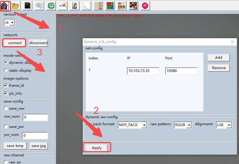
- Click here to download the image viewing tool hbplayer.
- Open hbplayer and set the network address (ensure the PC can ping the board). Click "Apply" to apply the settings, then click "Connect" to view the real-time video stream. The real-time preview operation is illustrated in the figure below.
Error Codes
Below are common sensor error codes and basic troubleshooting directions:
| Error Code | Definition | Troubleshooting Direction |
|---|---|---|
| 203 | HB_CAM_INIT_FAIL | Sensor initialization failed; typically caused by I2C communication failure or unsupported sensor mode configuration |
| 205 | HB_CAM_START_FAIL | Sensor start failed; typically caused by I2C communication failure or unsupported sensor mode configuration |
| 207 | HB_CAM_I2C_WRITE_FAIL | Sensor I2C communication failed. |
| 217 | HB_CAM_SENSOR_POWERON_FAIL | Sensor power-on failed; possibly due to incorrect sensor GPIO configuration. |
| 218 | HB_CAM_SENSOR_POWEROFF_FAIL | Sensor power-off failed; possibly due to incorrect sensor GPIO configuration. |
FAQ
control-tool Usage Instructions
Navigate to the tuning directory:
cd /app/tuning_tool/control_tool
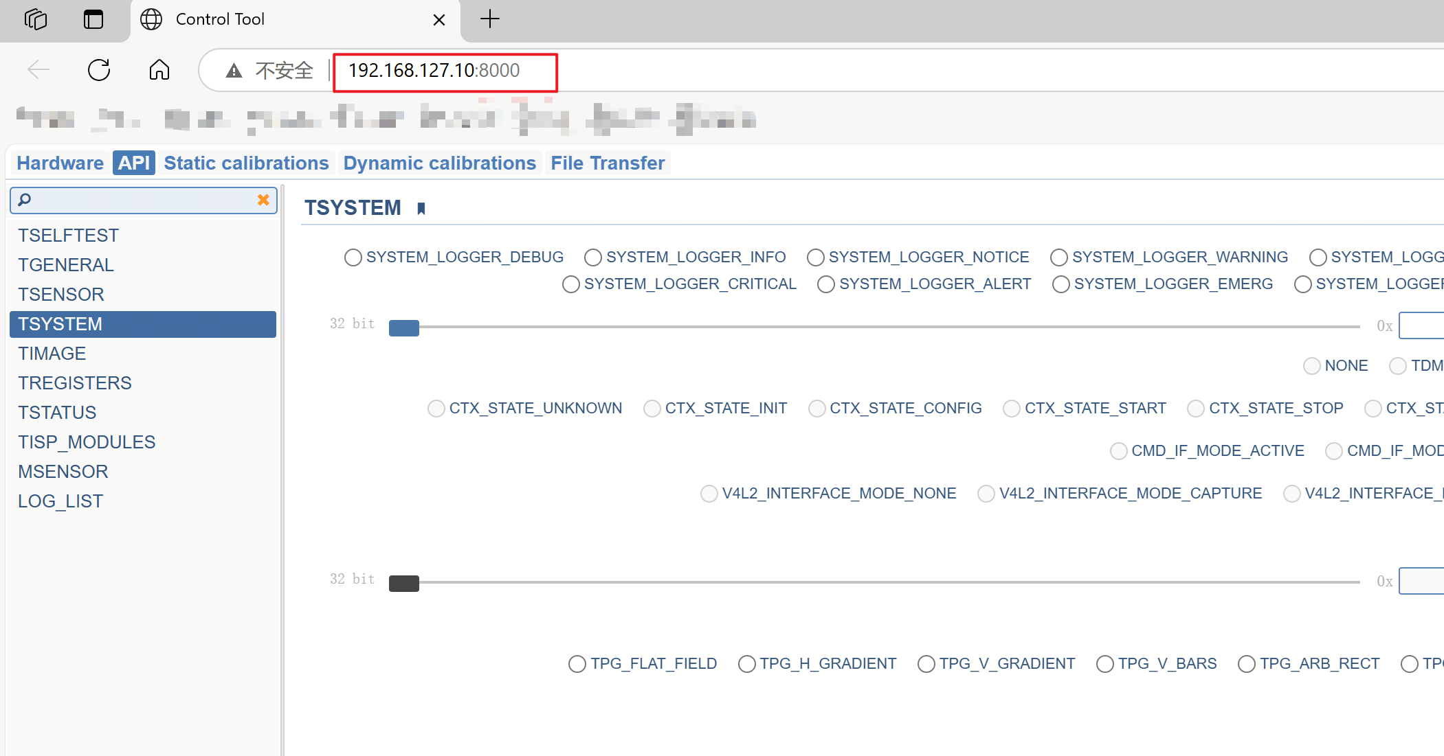
Follow the interactive prompts and execute the startup script: sh server_isp*_8000.sh.
The ISP hardware contains two IP cores, each of which can run independently. To enable ISP control, run the script: sh server_isp0_8000.sh.
The startup method is shown in the figure below.

The script automatically detects the board's IP address, checking the eth1 network interface by default. To switch to eth0, modify the script by setting eth_id=eth0. The modification location is shown in the figure below.
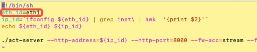
Diagram illustrating how to modify the communication address:
V4L2 Sensor Bring-up
V4L2 Sensor Driver Development Guide
The S100 Camsys sensor V4L2 driver software framework follows the standard V4L2 sub-device driver model.

Using the IMX219 driver as an example, the following describes the V4L2 driver development process for a MIPI-direct-connected sensor. The IMX219 driver source code is located at: kernel/drivers/media/i2c/imx219.c.
Define the Sensor's Private Structure
The IMX219 private structure is as follows:
struct imx219 {
        struct v4l2_subdev sd;
        struct media_pad pad;
        struct i2c_client *i2c_client;
        ...
        struct v4l2_ctrl *xxx_ctrl;
        ...
};
sd: V4L2 sub-device handle, used to operate subdev ops;pad: Media pad, used to establish media links with downstream modules;i2c_client: I2C client handle, used to communicate with the sensor over the I2C bus;xxx_ctrl: V4L2 control attributes (e.g., exposure, flip, blank); implementation is optional;
Implement V4L2 Callback Functions
A V4L2-compliant sensor driver must implement certain ops functions, which the V4L2 framework uses to control the sensor:
static const struct v4l2_subdev_ops imx219_subdev_ops = {
        .core = &imx219_core_ops,
        .video = &imx219_video_ops,
        .pad = &imx219_pad_ops,
};
This implements the V4L2 subdev ops callbacks, including core ops, video ops, and pad ops.
static const struct v4l2_subdev_pad_ops imx219_pad_ops = {
        .enum_mbus_code = imx219_enum_mbus_code,
        .get_fmt = imx219_get_pad_format,
        .set_fmt = imx219_set_pad_format,
        .enum_frame_size = imx219_enum_frame_size,
};
The pad ops define callback interfaces for format configuration and negotiation, which must be implemented.
static const struct v4l2_subdev_video_ops imx219_video_ops = {
        .s_stream = imx219_set_stream,
};
The video ops primarily define the sensor stream start/stop interface, which must be implemented.
static const struct v4l2_subdev_core_ops imx219_core_ops = {
        .subscribe_event = v4l2_ctrl_subdev_subscribe_event,
        .unsubscribe_event = v4l2_event_subdev_unsubscribe,
};
The core ops define functionalities such as ioctl event handling, which are optional.
static const struct v4l2_subdev_internal_ops imx219_internal_ops = {
        .open = imx219_open,
};
The internal ops define callbacks for managing the sub-device's lifecycle (e.g., open, close, release), implemented as needed.
Sensor Probe Function
static int imx219_probe(struct i2c_client *client)
{
        imx219 = devm_kzalloc(&client->dev, sizeof(*imx219), GFP_KERNEL); // 1
        if (!imx219)
                return -ENOMEM;
        ...
        v4l2_i2c_subdev_init(&imx219->sd, client, &imx219_subdev_ops);  // 2

        imx219->sd.flags |= V4L2_SUBDEV_FL_HAS_DEVNODE |
                        ┆   V4L2_SUBDEV_FL_HAS_EVENTS;
        imx219->sd.entity.function = MEDIA_ENT_F_CAM_SENSOR;
        imx219->pad.flags = MEDIA_PAD_FL_SOURCE;
        ret = media_entity_pads_init(&imx219->sd.entity, 1, &imx219->pad);  // 3

        ret = v4l2_async_register_subdev_sensor(&imx219->sd);  // 4

        ...
}
- Initialize the sensor structure and allocate memory;
- Initialize a V4L2 subdev and bind it to the I2C client;
- Initialize the media entity's pad information so the media controller knows the sensor has one output pad that can connect to downstream modules;
- Asynchronously register the sensor subdev with the V4L2 framework;
Sensor Device Tree
By default, S100 loads the IMX219 device tree. The device tree format is shown below. To connect a different MIPI sensor, override the IMX219 DTS using a DTS overlay.
&i2c1 {
        status = "okay";

        imx219@10 {
                status = "okay";
                compatible = "sony,imx219";
                ...
                reg = <0x10>; // Sensor I2C address
                ...
                port {
                        cam_to_mipi_csi0: endpoint {  // MIPI-related properties
                                remote-endpoint = <&rdk_s100_mipi_csi0_from_cam>;  // Connected to MIPI RX0
                                clock-lanes = <0>;
                                data-lanes = <1 2>;
                                link-frequencies =
                                        /bits/ 64 <456000000>;
                                virtual-channel = <0>;
                        };
                };
        };
};

&mipi_host0 {
        ports {
                port@0 {
                        rdk_s100_mipi_csi0_from_sensor0: endpoint {
                                remote-endpoint = <&sensor0_to_mipi_csi0>;
                                clock-lanes = <0>;
                                data-lanes = <1 2>;    // MIPI data lanes: 2-lane
                                lane-rate = <1728>;    // MIPI data rate
                                vc_id = <0>;            // Virtual channel ID from sensor
                                emb-en = <1>;            // Whether sensor output includes embedded data
                        };
                };
        };
};
V4L2 GMSL SerDes Interface Usage Guide
The S100 Camsys supports sensors connected via Maxim's serializer. The camera daughterboard includes the Maxim deserializer MAX96712 by default. GMSL sensors are also integrated into the V4L2 framework as V4L2 subdevs. The serializer and deserializer drivers provide function sets for GMSL sensor drivers but are not implemented as V4L2 subdevs themselves.

SerDes-related data structures and callback function definitions are located in kernel/include/media/i2c/serdes_core.h. Include this header file: #include <media/i2c/serdes_core.h>.
This section uses the AR0820C GMSL sensor as an example to illustrate Camsys GMSL sensor development.
Add New Members to the Sensor Structure
struct ar0820 {
        ...
        struct serdes_device *ser_dev;
        struct serdes_device *dser_dev;
        struct serdes_ctx g_ctx;
        ..
};
The sensor driver needs to include two structures, ser_dev and dser_dev, for operating the serializer and deserializer.It must also include the serdes context member g_ctx to store SerDes-related properties. The main structure members are described as follows:
struct serdes_ctx {
        u32 serdes_csi_link;    // Stores the deserializer's port value in the sensor driver
        u32 ser_reg;            // Target value for serializer I2C address mapping
        u32 sdev_reg;           // Actual I2C address of the sensor
        u32 sdev_def;           // Target value for sensor I2C address mapping
        struct device *sen_dev;
        u32 lane_num;           // Stores the number of MIPI data lanes connecting the sensor to the serializer in the sensor driver
        u32 data_type;          // Stores the data type output by the sensor in the sensor driver
        u32 dst_vc;             // Stores the virtual channel of the sensor output in the sensor driver
};
SerDes Callback Functions
Both the serializer and deserializer provide the following callback functions for use in the sensor driver. These callbacks must be invoked using the SERDES_OP macro.
/* By default, a return value >= 0 indicates success; a return value < 0 indicates failure */
struct serdes_ops {
        /* Initialize serializer and deserializer with basic configurations only */
        int (*init)(struct serdes_device *serdes_dev);
        /* Currently used for additional initialization of d457 -> MAX9295A, enabling all 4 pipes of MAX9295A */
        int (*init_ex)(struct serdes_device *serdes_dev);
        /* Reserved */
        int (*reset)(struct serdes_device *dev);
        /* Pass DTS-parsed values to the serializer and deserializer via serdes_ctx */
        int (*set_ctx)(struct serdes_device *serdes_dev,
                       struct serdes_ctx *ctx);
        /* Used by the deserializer to establish a link. By default, link is disabled; this op enables it */
        int (*setup_link)(struct serdes_device *serdes_dev,
                          struct device *sen_dev);
        /* remote_contrl_get -> map_addr -> remote_contrl_put are used together to ensure stability of sensor/serializer during I2C address remapping */
        int (*remote_contrl_get)(struct serdes_device *serdes_dev,
                                 struct device *sen_dev);
        int (*remote_contrl_put)(struct serdes_device *serdes_dev);
        /* Called by the serializer to remap I2C addresses of both serializer and sensor */
        int (*map_addr)(struct serdes_device *serdes_dev);
        /* Serializer pulls high a specific MFP */
        int (*enable_mfp)(struct serdes_device *serdes_dev, uint8_t gpio_index);
        /* Serializer pulls low a specific MFP */
        int (*clear_mfp)(struct serdes_device *serdes_dev, uint8_t gpio_index);
        /* Deserializer enables MIPI TX to start streaming. Serializer TX is enabled by default, so no explicit call is needed */
        int (*set_stream)(struct serdes_device *serdes_dev,
                          struct device *sen_dev, int enable);
        /* Configure GMSL video pipe attributes for both serializer and deserializer, parsed from DTS. By default, configures pipe-Z */
        int (*set_pipe)(struct serdes_device *serdes_dev,
                        struct device *sen_dev);
        /* For complex scenarios, configure GMSL video pipe data flexibly per pipe */
        int (*set_pipe_ex)(struct serdes_device *serdes_dev, struct device *sen_dev,
                           uint8_t pipe, uint8_t vc_id, uint8_t data_type);
        /* Check if the deserializer has an available pipe based on virtual channel ID. Returns available pipe ID (0-3).
           Used by D457 sensor before streaming, paired with release_pipe_id */
        int (*get_pipe_id)(struct serdes_device *serdes_dev,
                           uint8_t vc_id);
        /* Release the deserializer's video pipe after use */
        int (*release_pipe_id)(struct serdes_device *serdes_dev,
                               uint8_t pipe_id);
};
- In the sensor probe function, certain SerDes ops must be called to perform software initialization, parse DTS values, and pass them via
set_ctxto both serializer and deserializer drivers.
ret = SERDES_OP(priv->ser_dev, set_ctx, priv->ser_dev, &priv->g_ctx);
ret = SERDES_OP(priv->dser_dev, set_ctx, priv->dser_dev, &priv->g_ctx);
These calls establish a software-level link between the sensor driver and both serializer/deserializer by invoking their respective set_ctx functions.
        ret = SERDES_OP(priv->dser_dev, init, priv->dser_dev);
        ret = SERDES_OP(priv->dser_dev, setup_link, priv->dser_dev, sen_dev);
        ret = SERDES_OP(priv->dser_dev, remote_contrl_get, priv->dser_dev,
        ret = SERDES_OP(priv->ser_dev, map_addr, priv->ser_dev);
        ret = SERDES_OP(priv->dser_dev, remote_contrl_put, priv->dser_dev);
        ret = SERDES_OP(priv->ser_dev, init, priv->ser_dev);
        ret = SERDES_OP(priv->ser_dev, set_pipe, priv->ser_dev, sen_dev);
        ret = SERDES_OP(priv->dser_dev, set_pipe, priv->dser_dev, sen_dev);
        ret = SERDES_OP(priv->ser_dev, clear_mfp, priv->ser_dev,
                        priv->mfp_reset);
        ret = SERDES_OP(priv->ser_dev, enable_mfp, priv->ser_dev,
                        priv->mfp_reset);
These ops perform initialization of SerDes link, address mapping, pipe configuration, MFP control, etc.
- In
s_stream, configure the deserializer to start streaming and enable the serializer's MFP:
SERDES_OP(priv->ser_dev, enable_mfp, priv->ser_dev, priv->mfp_trigger);
SERDES_OP(priv->dser_dev, set_stream, priv->dser_dev, sen_dev, 1);
Sensor Device Tree
The S100 V4L2 GMSL sensor loads the AR0820C DTS by default. The GMSL sensor device tree is organized as follows:
ar0820@11 {
                compatible="d-robotics,ar0820";
                reg = <0x11>;     // Mapped address
                addr = <0x10>;    // Actual sensor I2C address
                ......
                mfp-reset = <0>;  // Reset pin connected to serializer's MFP
                mfp-trigger = <7>;// Trigger pin connected to serializer's MFP
                d-robotics,serdes-ser-device = <&ser_a>;  // Linked to serializer on Link A
                d-robotics,serdes-dser-device = <&dser>;  // Connected to deserializer
                status = "okay";

                port {
                        cam_0_to_mipi_csi4: endpoint {    // Connected to MIPI RX4
                                remote-endpoint = <&mipi_csi4_from_cam_0>;
                                virtual-channel = <0>;
                        };
                };
};
Sensor DTBO File Configuration Guide
The S100 Uboot supports Device Tree Blob Overlay (DTBO) functionality, allowing users to add or modify (but not delete) nodes in the currently loaded DTB without changing the original DTS file.
Generating Sensor DTBO Files
- Write a
.dtsofile:
#include <dt-bindings/gpio/gpio.h>

/dts-v1/;
/plugin/;

/ {
    fragment@1 {
        target-path = "/soc/i2c@39450000/";
            __overlay__ {
                status = "okay";
                d457@11 {
                    compatible="intel,d4xx";
                    reg = <0x11>;
                    def-addr = <0x10>;
                    width = <640>;
                    height = <480>;
                    cam-type = "Depth";
                    data_type = <0x2e>;
                    lane_num = <2>;
                    vc_id = <0>;
                    d-robotics,serdes-ser-device = <&ser_a>;
                    d-robotics,serdes-dser-device = <&dser>;
                    status = "okay";

                    port {
                        sensor_0_to_mipi_csi4: endpoint {
                            remote-endpoint = <&mipi_csi4_from_sensor_0>;
                            virtual-channel = <0>;
                        };
                    };
                };
           };
      };
};
- Compile the DTBO on the board:
- Install the
dtctool:
sudo apt install device-tree-compiler -y
- Preprocess the
.dtsofile (only needed if the.dtsoincludes headers or macros):
# Get DTS header path
HEADER_DIR=$(find /usr/src -maxdepth 1 -type d -name "linux-headers-*" | sort -Vr | head -n 1)
DTS_HEAD_PATH="$HEADER_DIR/include"

# Preprocess .dtso to generate .dtbi
cpp -nostdinc -I "$DTS_HEAD_PATH" sample.dtso > sample.dtbi
- Compile to generate the final
.dtbofile:
If you have a .dtbi file:
dtc -q -@ -I dts -O dtb -o sample.dtbo sample.dtbi
If you don’t have a .dtbi file:
dtc -q -@ -I dts -O dtb -o sample.dtbo sample.dtso
Enabling Sensor DTBO at Boot
- Place the compiled
.dtbofile in/boot/overlays.
If the/boot/overlaysdirectory doesn’t exist, create it manually or installhobot-camera.debto obtain the directory and example D457 sensor DTBO files.

- Modify
config.txtto specify the DTBO file to load.
Ifconfig.txtdoesn’t exist, create it manually.

Edit config.txt as follows:
dtbo_file_path=/overlays/v0p5_d457_2v_depth_color.dtbo
- Reboot the board to apply the DTBO configuration. In debug builds of Uboot, you can verify DTBO loading from the boot logs.

Sensor Gain LUT Table Implementation Guide
For RAW-format sensors interfaced with the S100 ISP imaging system, in addition to writing the V4L2 sensor driver, you must also create a shared object (.so) containing the sensor gain LUT (Look-Up Table), including analog gain (again) LUT, digital gain (dgain) LUT, etc.
Human perception of brightness is closer to a logarithmic scale than linear, and the dB unit better matches this perception. Therefore, the gain arrays stored in the S100 ISP sensor gain LUT must contain continuous dB-unit sensor gain values corresponding to actual sensor register settings. This allows the ISP to look up the correct register values when adjusting sensor gain and send them to the sensor.
Below is an example using the IMX219 sensor to illustrate how to build the V4L2 sensor LUT .so file.
The IMX219 sensor gain LUT implementation directory in the SDK is:
hobot-camera/v4l2/v4l2_helper/imx219_v4l2
- Add the following files:
<sensor_name>_camera_helper.cMakefile- Version file `version.mk
imx219_v4l2
├── imx219_camera_helper.c
├── Makefile
└── version.mk
- In the
xxx_helper.cfile, create theagainLUT table and thedgainLUT table. Each LUT is an array of typeuint32_t, containing up to 256 entries. Each entry holds the register configuration value corresponding to a specific gain. The dB values corresponding to adjacent entries must be continuous. Takingimx219as an example:
static uint32_t imx219_again_lut[] = {
        0x00,   // 0 dB
        0x05,   // approx. 0.2 dB
        0x0B,   // approx. 0.4 dB
        0x0F,   // approx. 0.6 dB
        0x15,   // approx. 0.8 dB
        ......
        0xE7,   // approx. 20.4 dB
        0xE8,   // approx. 20.6 dB
        0xffff, // end flag
};

static uint32_t imx219_dgain_lut[] = {
        0x0100,  // 0 dB
        0x0106,  // approx. 0.2 dB
        0x010c,  // approx. 0.4 dB
        0x0112,  // approx. 0.6 dB
        ......
        0x0f53,  // approx. 23.6 dB
        0x0fa9,  // approx. 23.8 dB
        0x0fd9,  // approx. 24.0 dB
        0xffff,  // end flag
};
The last entry of each LUT must always be 0xffff.
- Implement the
again index to reganddgain index to regcallback functions, along with the interface to retrieve these callbacks. You can reuse the implementation from the IMX219:
typedef uint32_t (*AGainIndexToReg_t)(uint8_t);  // Input: uint8_t index; Output: uint32_t sensor register configuration value
typedef uint32_t (*DGainIndexToReg_t)(uint8_t);  // Same as above

typedef struct {
        AGainIndexToReg_t again_index_to_reg_callback;
        DGainIndexToReg_t dgain_index_to_reg_callback;
} Callbacks;   // Callback structure; no modification needed

uint32_t again_index_to_reg_function(uint8_t isp_index)
{
        if (isp_index >= sizeof(imx219_again_lut)/sizeof(uint32_t))
                isp_index = sizeof(imx219_again_lut)/sizeof(uint32_t) - 1;
        return imx219_again_lut[isp_index];
}

uint32_t dgain_index_to_reg_function(uint8_t isp_index)
{
        if (isp_index >= sizeof(imx219_dgain_lut)/sizeof(uint32_t))
                isp_index = sizeof(imx219_dgain_lut)/sizeof(uint32_t) - 1;

        return imx219_dgain_lut[isp_index];
}

Callbacks cb = {again_index_to_reg_function,
                dgain_index_to_reg_function,};

// get_index_to_reg_callbacks
Callbacks* get_index_to_reg_callbacks() {
        return &cb;
}
The generated shared library should be named lib<sensor_name>_v4l2.so. At runtime, this .so file will be automatically matched and loaded via dlopen, and the LUT tables will be retrieved through the exported symbols.
Exposure Synchronization Sensor Driver Instructions
The S100 camsys SerDes provides trigger-related interfaces that can be called within the sensor driver to configure LPWM hardware and enable LPWM.
Hardware-synchronized exposure currently supports only GMSL sensors. The correct trigger MFP pin must be configured in the sensor's device tree source (DTS).
SERDES_OP(priv->dser_dev, trigger_cfg, priv->dser_dev, sen_dev, period, duty);
Call trigger_cfg during the sensor's initialization when setting the format to apply LPWM configuration.
periodis in nanoseconds (ns), calculated as(1000000 / fps) * 1000.dutyis also in nanoseconds (ns); if there are no special requirements, it can be set to10000.
SERDES_OP(priv->dser_dev, trigger_enable, priv->dser_dev, sen_dev, enable);
Call trigger_enable when starting or stopping the video stream to turn LPWM output on or off.