Camsys Subsystem
System Overview
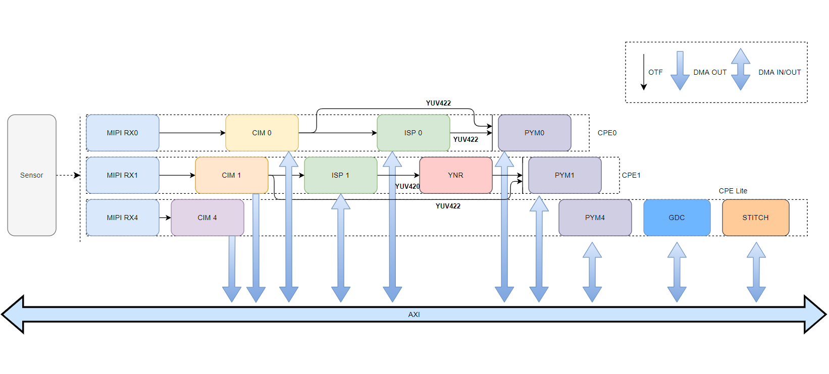
The S100 camsys subsystem includes the Camera sensor (including SerDes), VIN (including MIPI, CIM), ISP, PYM, GDC, YNR, and STITCH modules.
| Abbreviation | Full Name | Description |
|---|---|---|
| MIPI | Mobile Industry Processor Interface | Standard defined by the MIPI Alliance for mobile industry processor interfaces |
| CSI | Camera Serial Interface | Camera serial interface |
| IPI | Image Pixel Interface | Image transmission interface between MIPI and CIM |
| FOV | Field of View | Field of view |
| SER | Serializer | Serializer |
| SerDes | Serializer and Deserializer | Serializer and deserializer |
| DES | Deserializer | Deserializer |
| CIM | Camera Interface Manager | Camera access management module supporting online or offline operation |
| VIN | Video In (CIM+MIPI+LPWM+VCON) | Video input module |
| ISP | Image Signal Processor | Image signal processor |
| PYM | Pyramid | Pyramid processing module: image downscaling and ROI |
| GDC | Geometric Distortion Correction | Geometric distortion correction module |
| VPF | Video Process Framework (VIN+ISP+PYM..) | Video processing management module |
| VIO | Video In/Out (VIN+VPM) | Video input/output module |
| STITCH | Stitch hardware Module | Image stitching processing module |
| CAMSYS | Camera System (Camera+VPF) | Camera image system |
Camsys Hardware Block Diagram
Submodules
CIM
CIM (Camera Interface Manager) is a dedicated hardware block for receiving MIPI-RX IPI image data. CIM handles simultaneous input of multiple image streams and adjusts the timing of the MIPI IPI interface to match the timing requirements of downstream hardware or DDR, delivering images directly via hardware or through DDR to the ISP and PYM.
- The S100 has three CIM modules: CIM0, CIM1, and CIM4.
- A single CIM supports a maximum input of 4V * 8M * 30fps and supports RAW8, RAW10, RAW12, RAW14, RAW16, RAW20, and YUV422-8Bit image formats.
- CIM0 and CIM1 support direct hardware (OTF) output to ISP and PYM and also support offline output to DDR; CIM4 supports only offline output.
- The maximum input width for IPI0 of CIM0 is 5696; all other IPIs in CIM0 and all IPIs in other CIMs support a maximum input width of 4096.
ISP
ISP (Image Signal Processor) is a dedicated engine for image signal processing.
ISP functions include various algorithmic processing of raw images, image characteristic statistics, color space conversion, and time-division multiplexing control of multiple channels, ultimately producing clearer, more accurate, and higher-quality images.
- The S100 has two ISP modules: ISP0 and ISP1.
- Each ISP hardware IP supports up to 12 sensor inputs.
- Maximum ISP processing resolution: 4096 × 2160.
- ISP processing pipeline is shown below:
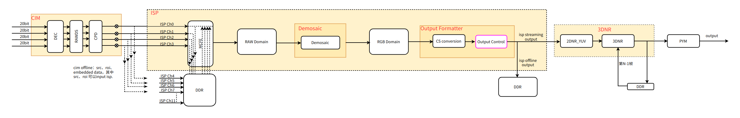
- MCFE:
Multi-Context Front End, used for multi-channel scheduling control and buffer management in ISP, processing multi-camera images sequentially (one by one). - RAW Domain:
RAW-domain image processing includes input port (with input crop functionality), channel switch, input formatter, sensor offset linear, digital gain, gamma FE (i.e., decompander), gamma_sqrt, raw frontend, static defect correction, sinter, chromatic aberration correction, gamma_sq, gamma BE, static white balance, radial shading correction, mesh shading correction, digital gain iridix, iridix, demosaic, etc. - RGB Domain:
RGB-domain image processing includes purple fringe correction, color matrix, gamma RGB forward SQ, crop, CNR, gamma RGB reverse SQ, RGB gamma, etc. - Output formatter:
Performs color space (CS) conversion, transforming RGB channel data into formats such as YUV, and handles output control.
YNR
YNR is a Digital Noise Reduction module operating in the YUV domain, supporting both 2DNR and 3DNR modes.
- The S100 has one YNR module, YNR1, which only supports the ISP1-online-YNR1-online-PYM1 scenario.
- In 3DNR mode, the maximum supported resolution is 2048×2048; in 2DNR mode, it supports up to 3840×2160.
PYM
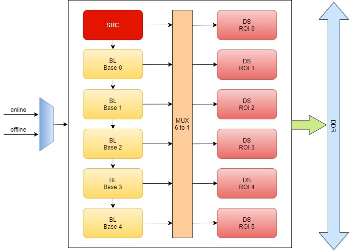
PYM (Pyramid) is a hardware acceleration module that processes input images in pyramid layers and outputs them to DDR.
- The S100 has three PYM modules: PYM0, PYM1, and PYM4.
- SRC layer: Represents the source image layer.
- BL layer: Represents bilinear downsampled layers; BL Base 0~4 correspond to 1/2, 1/4, 1/8, 1/16, and 1/32 of the source image, respectively.
- DS layer: Output layer; each layer can arbitrarily select an input layer (SRC or BL0~4), perform downsampling and ROI processing, and then output to DDR.
- Maximum input width and height: 4096; minimum input width and height: 32.
- Downscaling ratio: (1/2, 1]; upscaling is not supported.
- Performance: PYM0/1 support 4K@120fps; PYM4 supports 4K@90fps but does not support online input.
GDC
GDC is a hardware module capable of performing perspective transformation, distortion correction, and rotation at specific angles (0°, 90°, 180°, 270°) on input images.
Typical supported input resolutions include: 3840×2160, 2688×1944, 1920×1080, 1280×720, 640×480, and 480×320.
Hardware specifications:
- Maximum resolution: 3840×2160
- Minimum resolution: 96×96 (odd-numbered rows or columns are not supported)
- Performance: 3840×2160 @ 60fps
- Operating mode: DDR → GDC → DDR
- Input format: YUV420 semi-planar
- Output format: YUV420 semi-planar
Introduction to GDCTool
GDC Tool is a PC-based utility that enables offline simulation of GDC processing effects. Users can prepare JPEG-format images, load them into GDC Tool for offline correction, and then either directly save a config.bin file for hardware correction or save a layout.json file to generate a config.bin for hardware correction.
Launching GDC Tool
-
Windows Environment
- Installation prerequisites: Requires Node.js. See: https://nodejs.cn/download/
- Install dependencies: Open a Windows command prompt, navigate to the GDC tool directory (e.g.,
gdc-tool-gui-xxxx-windows), and runnpm install express. - Launch the application: In the command prompt, navigate to the tool directory and run
node.exe app.js. Then open Chrome and go to http://localhost:3000/.
-
Unix Environment
- Installation prerequisites (MacOS): Run
brew install node. - Install dependencies: In the tool directory, run
npm install --production. - Launch the application: Run
node app.jsand open http://localhost:3000/ in your browser.
- Installation prerequisites (MacOS): Run
Transformation Modes in GDC Tool
Six transformation modes are available: Affine, Equisolid, Equisolid (cylinder), Equidistant, Custom, and Keystone+dewarping. These correspond to transformation modes described in the transformation_t section of the GDC Bin API documentation. The following table describes the purpose of each transformation mode:
| Transformation Mode | Purpose |
|---|---|
| Affine | A linear transformation providing simple image rotation without distortion correction |
| Equisolid | Panoramic transformation with the largest transformation grid |
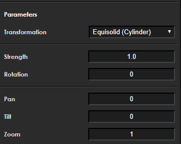
| Equisolid (cylinder) | Cylindrical transformation |
| Equidistant | Equidistant transformation, where distances after transformation remain equidistant |
| Custom | User-defined custom transformation |
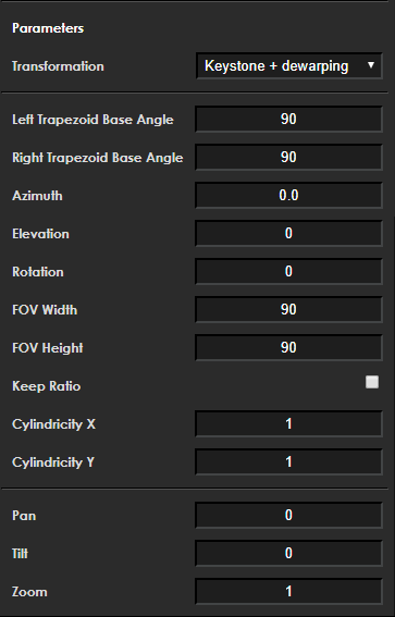
| Keystone+dewarping | Compared to Equidistant, dewarp_keystone adds two parameters: trapezoid_left_angle and trapezoid_right_angle. By default, both are 90°, yielding the same result as Equidistant. |
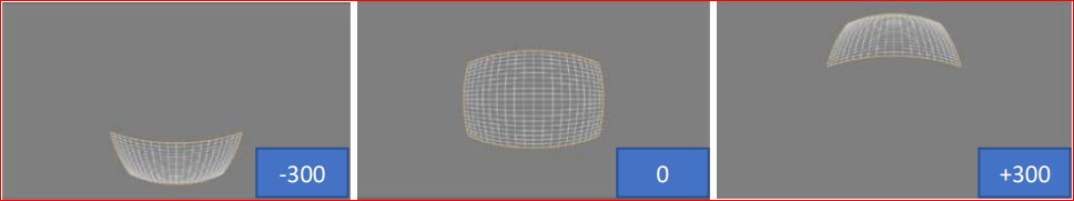
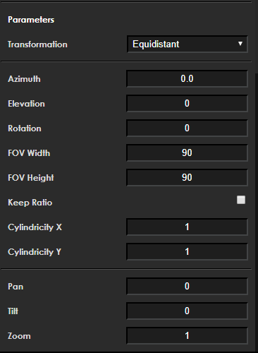
All transformation types share three common parameters: Pan, Tilt, and Zoom. (Example: Equidistant transformation with input/output resolution of 1280×720.) In the following output images, the blue rectangle indicates the effect when only the specified parameter is set to the given value, while all other parameters remain at their defaults.
-
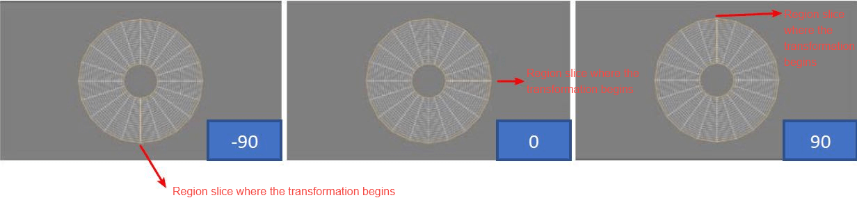
Pan
Horizontally offsets the transformation grid by a given number of pixels within the range (-1280, +1280), as shown below:
-
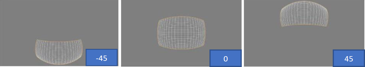
Tile
Vertically offsets the transformation grid by a given number of pixels within the range (-720, +720), as shown below:
-
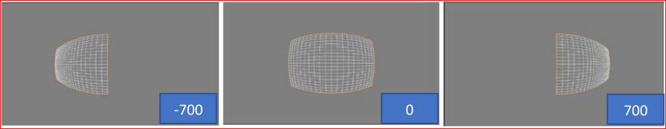
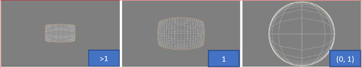
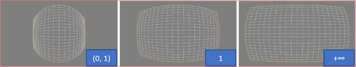
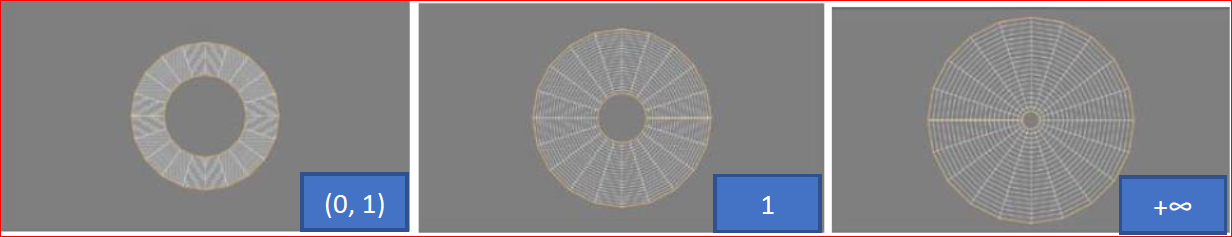
Zoom
Scales the transformation output by a given factor within the range (0, +∞), where (0, 1) denotes values greater than 0 and less than 1, as shown below:
-
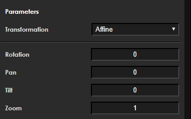
Affine
-
Function Description
Provides a linear transformation.
-
Member Description
Member Description int32_t pan Default: 0; no modification int32_t tilt Default: 0; no modification zoom Scales the transformation output by the provided factor. When rotation angle is 180° or 270°, this value must be ≥1.03 double angle (rotation) Image rotation angle: 0°/90°/180°/270° Note!Input and output widths must be aligned to 16-byte boundaries.
When the rotation angle is 180° or 270°, the zoom parameter must be ≥1.03.
-
-
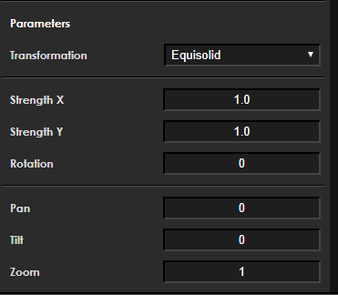
Equisolid
-
Function Description
This transformation provides equisolid (panoramic) correction and displays the result as a projection onto a plane.
-
Member Description
Member Description int32_t pan Default: 0; no modification int32_t tilt Default: 0; no modification zoom Scales the transformation output by the provided factor double strengthX Transformation strength along the X-axis (non-negative parameter) double strengthY Transformation strength along the Y-axis (non-negative parameter) double angle (rotation) Image rotation angle: 0°/90°/180°/270° strength x adjustment effect: transformation strength along the X-axis, with values in the range (0, +∞), as shown below:
strength y debugging effect: the transformation intensity along the Y-axis, with a value range of (0, +∞). As shown below:
Rotation debugging effect: value range (-180, 180). As shown below:
 Note!
Note!The width of input and output dimensions must be aligned to 16-byte boundaries.
-
-
Equisold (cylinder)
-
Function Description
This transformation provides equirectangular (panoramic) correction and displays the result as a projection onto a plane.
-
Member Description
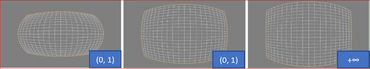
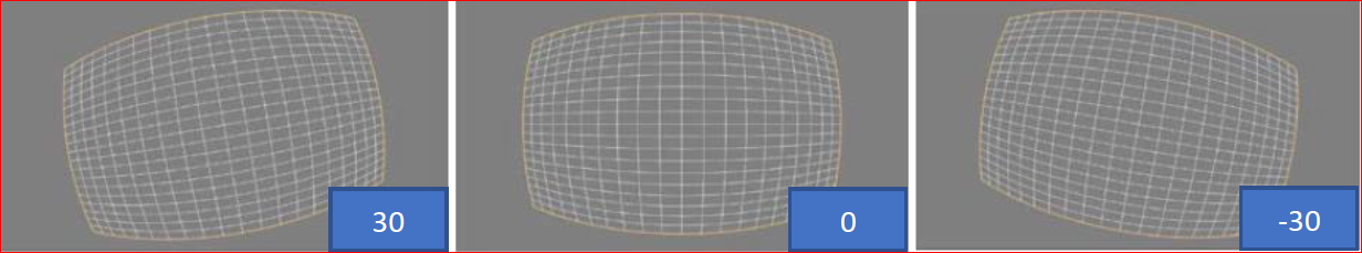
Member Description int32_t pan default 0, no modification int32_t tilt default 0, no modification zoom Scales the transformation output by the provided factor strength Intensity of the transformation double angle(rotation) Image rotation angle: 0/90/180/270 strength debugging effect: transformation intensity (0, +∞). As shown below:
rotation debugging effect: value range (-180, +180). As shown below:
 Note!
Note!The width of input and output dimensions must be aligned to 16-byte boundaries.
-
-
Equidistant
-
Function Description
The equidistant transformation includes many parameters that allow it to provide a variety of target planes for projection. This gives users greater freedom to select the desired region of the fisheye frame to be transformed.
-
Member Description
Member Description int32_t pan default 0, no modification int32_t tilt default 0, no modification zoom Scales the transformation output by the provided factor double angle(rotation) Image rotation angle: 0/90/180/270 double elevation Defines the elevation angle of the projection axis, ranging from 0 to 90 double azimuth Defines the azimuth angle of the projection axis. If the elevation parameter is 0, azimuth will have no visible effect int32_t keep_ratio When the "keep ratio" parameter is enabled, the FOV height parameter will be ignored, and its value will be automatically calculated to maintain equal stretching intensity in both horizontal and vertical directions double FOV_h Describes the size (in degrees) of the output field of view in the horizontal dimension. Valid values range from 0 to 180 double FOV_w Describes the size (in degrees) of the output field of view in the vertical dimension. Valid values range from 0 to 180 double cylindricity_y Describes the sphericity of the target projection along the Y-axis. This value ranges from 0 to 1, where 1 represents a spherical shape. If this value is set to 1 while "cylindricity_x" is set to 0, the projection will form a cylinder along the Y-axis double cylindricity_x Describes the sphericity of the target projection along the X-axis. This value ranges from 0 to 1, where 1 represents a spherical shape. If this value is set to 1 while "cylindricity_y" is set to 0, the projection will form a cylinder along the X-axis elevation debugging effect:
azimuth debugging effect:
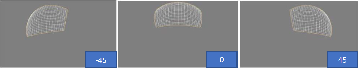
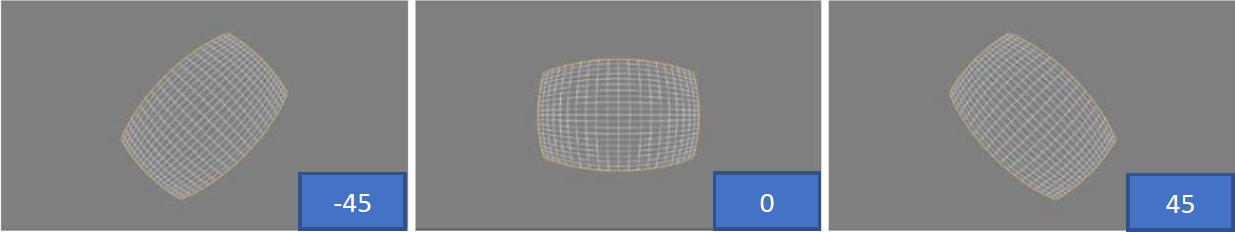
rotation debugging effect:
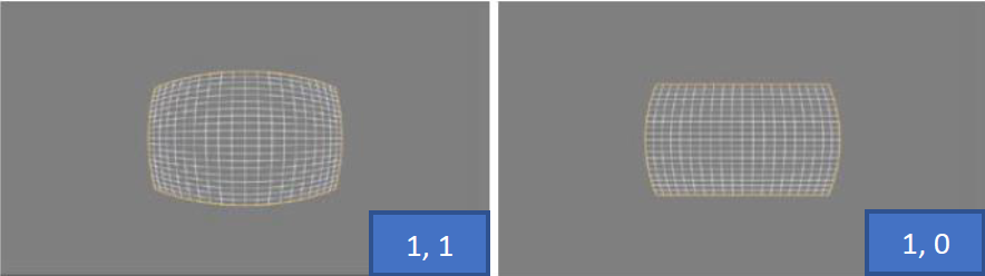
cylindricity x debugging effect:
Describes the sphericity of the target projection along the X-axis. This value ranges from 0 to 1, where 1 represents a spherical shape. If this value is set to 1 and cylindricity_y is set to 0, the projection will form a cylinder along the X-axis. As shown below:
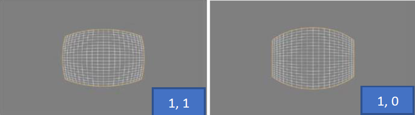
cylindricity y debugging effect:
Describes the sphericity of the target projection along the Y-axis. This value ranges from 0 to 1, where 1 represents a spherical shape. If this value is set to 1 and cylindricity_x is set to 0, the projection will form a cylinder along the Y-axis. As shown below:
 Note!
Note!The width of input and output dimensions must be aligned to 16-byte boundaries. Normal human vision is approximately 90 degrees. For transformations where cylindricity (see below) equals "0", setting both FOV width and height to 180 will cause infinite image stretching. If both cylindricity_x and cylindricity_y are set to 1, the projection will be spherical. If both are set to 0, the transformation will be rectangular.
-
-
Custom
-
Function Description
After applying the custom transformation, each polygon in the input image is transformed into a square. In other words, any four adjacent input points of any shape become a square after transformation, as shown in the figure below. However, the shape and position of the polygons will change after transformation.
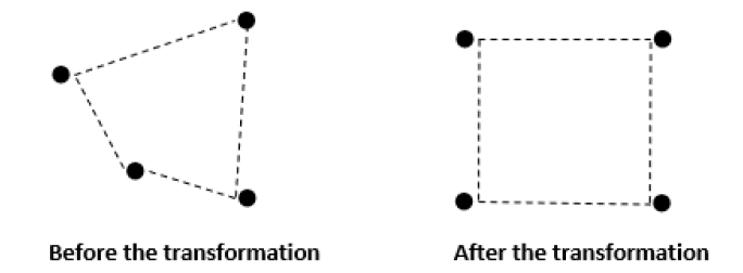
These are used to create transformations that cannot be described by any of the provided standard types. To correct arbitrary distortion, a special calibration file named config0.txt must be provided to the GDC tool, as shown in the figure below:
-
Member Description
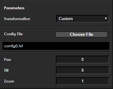
Member Description int32_t pan default 0, no modification int32_t tilt default 0, no modification zoom Scales the transformation output by the provided factor char custom_file[128] Name of the config.txt file custom_tranformation_t custom Parsed custom transformation structure Rules for the Config file should generally observe the following points:
-
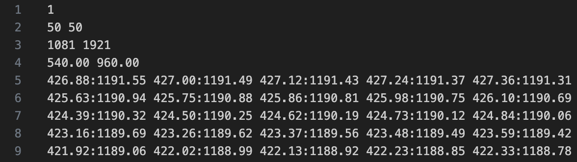
The first line enables full tile in pixel calculation: 1 means enable, 0 means disable.
-
The second line specifies the number of pixels to skip if full tile is enabled; these values must be greater than 0. Smaller numbers result in slower libgdc performance (slower performance means a larger config.bin file and longer time for libgdc to generate config.bin).
-
The third line specifies the number of calibration points in vertical and horizontal directions. The first value Y = 1081 indicates 1081 calibration points vertically, and the second value X = 1921 indicates 1921 calibration points horizontally.
-
The fourth line specifies the center point of the selected region, typically (Y-1)/2, (X-1)/2.
-
Calibration points must be non-negative integers or floats, and calibration points in adjacent rows must not be duplicated. e.g., The figure below shows a partial excerpt of the data. Rows 5 to 9 contain the coordinate values of calibration points in the source image, formatted as Y: X. In this example, there are a total of 1081x1921 calibration points.
-
Since calibration points must be equally spaced, the output image resolution depends on the number of calibration points.
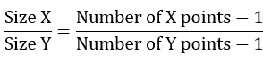
e.g., Output image Width = 100, Height calculated as 340, calculated as follows: 100/height = (96-1)/(324-1)
The figure below shows a simpler example of 3x3 coordinate point transformation: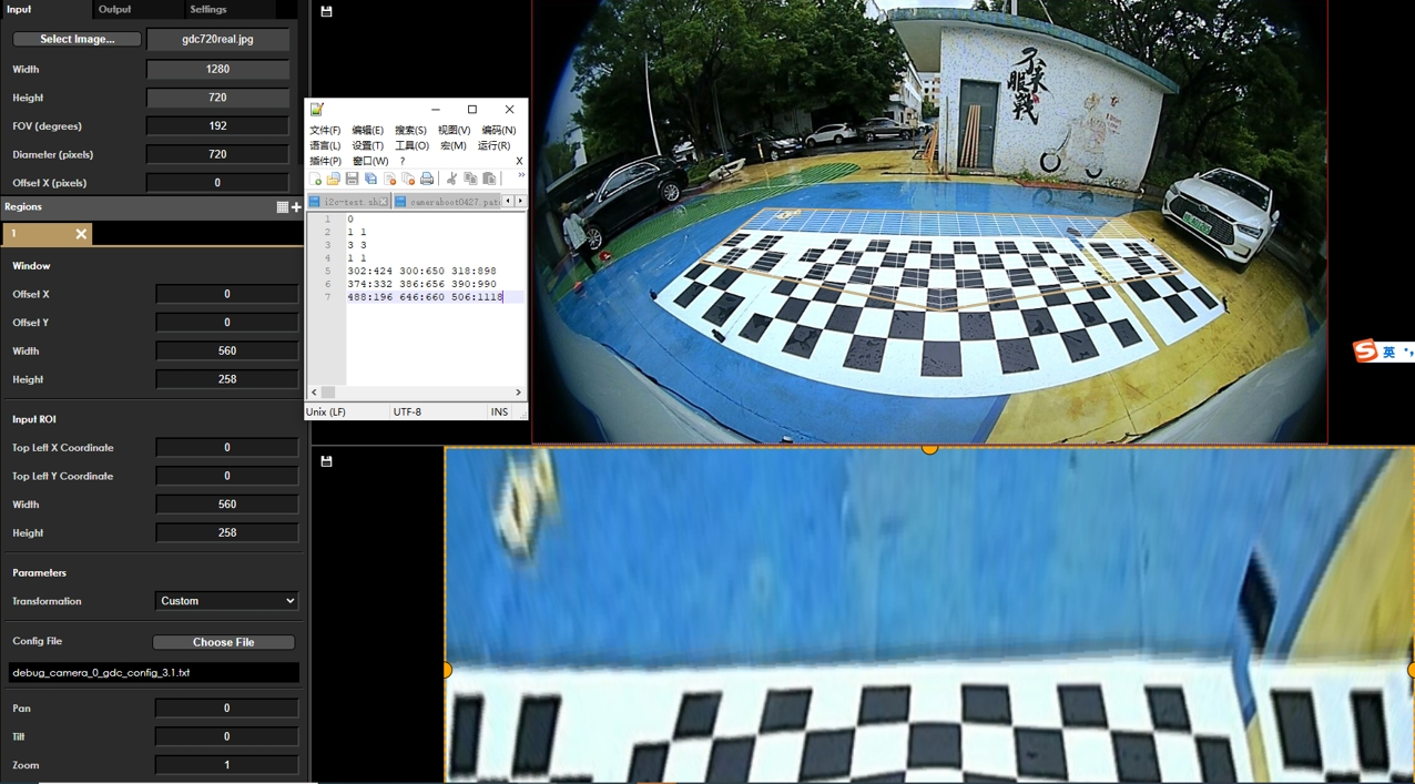
-
-
-
Keystone + Dewarping
-
Function Description
-
Member Description
Member Description int32_t pan default 0, no modification int32_t tilt default 0, no modification zoom Scales the transformation output by the provided factor double angle(rotation) Image rotation angle: 0/90/180/270 double elevation Defines the elevation angle of the projection axis, ranging from 0 to 90 double azimuth Defines the azimuth angle of the projection axis. If the elevation parameter is 0, azimuth will have no visible effect int32_t keep_ratio When the "keep ratio" parameter is enabled, the FOV height parameter will be ignored, and its value will be automatically calculated to maintain equal stretching intensity in both horizontal and vertical directions double FOV_h Describes the size (in degrees) of the output field of view in the horizontal dimension. Valid values range from 0 to 180 double FOV_w Describes the size (in degrees) of the output field of view in the vertical dimension. Valid values range from 0 to 180 double cylindricity_y Describes the sphericity of the target projection along the Y-axis. This value ranges from 0 to 1, where 1 represents a spherical shape. If this value is set to 1 while "cylindricity_x" is set to 0, the projection will form a cylinder along the Y-axis double cylindricity_x Describes the sphericity of the target projection along the X-axis. This value ranges from 0 to 1, where 1 represents a spherical shape. If this value is set to 1 while "cylindricity_y" is set to 0, the projection will form a cylinder along the X-axis double trapezoid_left_angle Default 90; range 0.1 to 90; in the transformation grid, the angle between the left boundary and the bottom boundary—see actual effect double trapezoid_right_angle Default 90; range 0.1 to 90; in the transformation grid, the angle between the right boundary and the bottom boundary—see actual effect Note!The width of input and output dimensions must be aligned to 16-byte boundaries.
-
GDC Tool Transformation Mode Parameter Description
The configuration file can be generated by the GDC tool and saved as layout.json. Different transformation modes have different parameters. Taking custom mode and keystone+dewarping mode as examples, the configuration parameters are explained below.
-
keystone+dewarping mode
{
    "inputRes": [
        1920, // Width of the input image resolution
        1080  // Height of the input image resolution
    ],
    "param": {
        "fov": 180,        // Field of view of the input image
        "diameter": 1080,  // Diameter of the input image; controls the overall size of the transformation grid
        "offsetX": 0,      // Horizontal offset of the transformation grid
        "offsetY": 0       // Vertical offset of the transformation grid
    },
    "outputRes": [
        1920, // Width of the output image resolution
        1080  // Height of the output image resolution
    ],
    "transformations": [
        {
            "transformation": "Dewarp_keystone", // Transformation mode"position": [ // ROI region settings for the output image
                0, // Horizontal offset of the output image's ROI
                0, // Vertical offset of the output image's ROI
                1920, // Width of the output image's ROI
                1080 // Height of the output image's ROI
            ],
            "param": {
                "left_base_angle": 90, // Default: 90; range: 0.1 to 90; in the transformation mesh, the angle of the left boundary relative to the bottom boundary
                "right_base_angle": 90, // Default: 90; range: 0.1 to 90; in the transformation mesh, the angle of the right boundary relative to the bottom boundary
                "azimuth": 90, // Defines the azimuth angle of the projection axis. If the elevation parameter is 0, the azimuth will have no visible effect.
                "elevation": 0, // Defines the elevation angle of the projection axis, ranging from 0 to 90.
                "rotation": 0, // Rotation angle to be applied to the output image
                "fovWidth": 90, // Specifies the horizontal field of view of the output image in degrees. Larger values result in a wider horizontal transformation mesh. Valid range: 0 to 180.
                "fovHeight": 90, // Specifies the vertical field of view of the output image in degrees. Larger values result in a taller vertical transformation mesh. Valid range: 0 to 180.
                "keepRatio": 0, // When "keepRatio" is set to 1, the fovHeight parameter is ignored and automatically calculated to maintain uniform stretching intensity in both horizontal and vertical directions.
                "cylindricityX": 1, // Describes the sphericity of the target projection along the X-axis. Values range from 0 to 1, where 1 represents a fully spherical projection. If set to 1 while "cylindricityY" is 0, the projection forms a cylinder along the X-axis.
                "cylindricityY": 1 // Describes the sphericity of the target projection along the Y-axis. Values range from 0 to 1, where 1 represents a fully spherical projection. If set to 1 while "cylindricityX" is 0, the projection forms a cylinder along the Y-axis.
            },
            "ptz": [
                0, // pan parameter
                0, // tilt parameter
                1 // zoom parameter
            ],
            "roi": { // Input image ROI region settings
                "x": 0, // Horizontal offset of the input image's ROI
                "y": 0, // Vertical offset of the input image's ROI
                "w": 1920, // Width of the input image's ROI
                "h": 1080 // Height of the input image's ROI
            }
        }
    ],
    "mode": "semiplanar420", // Processing format setting
    "eccMode": "eccDisabled", // ECC mode for processing
    "colourspace": "yuv" // Data format for processing
} -
Custom mode
{
    "inputRes": [
        1280, // Width of the input image resolution
        720 // Height of the input image resolution
    ],
    "param": {
        "fov": 192, // Field of view of the input image
        "diameter": 720, // Diameter of the input image, controlling the overall size of the transformation mesh
        "offsetX": 0, // Horizontal offset of the transformation mesh
        "offsetY": 0 // Vertical offset of the transformation mesh
    },
    "outputRes": [
        560, // Width of the output image resolution
        258 // Height of the output image resolution
    ],
    "transformations": [
        {
            "transformation": "Custom", // Transformation mode
            "position": [ // ROI region settings for the output image
                0, // Horizontal offset of the output image's ROI
                0, // Vertical offset of the output image's ROI
                560, // Width of the output image's ROI (must be ≤ outputRes width)
                258 // Height of the output image's ROI (must be ≤ outputRes height)
            ],
            "ptz": [
                0, // pan parameter
                0, // tilt parameter
                1 // zoom parameter
            ],
            "roi": { // Invalid in custom mode
                "x": 0, // Invalid in custom mode
                "y": 0, // Invalid in custom mode
                "w": 0, // Invalid in custom mode
                "h": 0 // Invalid in custom mode
            },

"param": {
                "customTransformation": "/path_to/camera_0_gdc.txt" // Path to the coordinate mapping file on the device
            }
        }
    ],
    "mode": "semiplanar420", // Processing format setting
    "eccMode": "eccDisabled", // ECC mode for processing
    "colourspace": "yuv" // Data format for processing
}Note!- Always set eccMode to "eccDisabled". Although other ECC modes are selectable, they have no actual effect.
- When parameters are fractional, ensure precision of at least 8 decimal places after floating-point computation; otherwise, the generated binary may differ.
- When populating the data structure or JSON, users must include all fields shown in the mode examples.
- In non-custom modes, the "roi" parameter in the configuration file specifies the ROI of the input image.
- The "position" parameter in the configuration file specifies the ROI of the output image.
-
Affine
Configuration file content as follows:{
"inputRes": [
1920,
1080
],
"param": {
"fov": 160,
"diameter": 1080,
"offsetX": 0,
"offsetY": 0
},
"outputRes": [
1920,
1080
],
"transformations": [
{
"transformation": "Affine",
"position": [
0,
0,
1920,
1080
],
"param": {
"rotation": 0
},
"ptz": [
0,
0,
1
],
"roi": {
"x": 0,
"y": 0,
"w": 1920,
"h": 1080
}
}
],
"mode": "semiplanar420",
"eccMode": "eccDisabled",
"colourspace": "yuv"
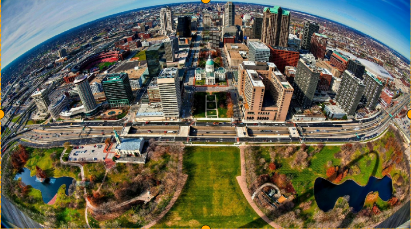
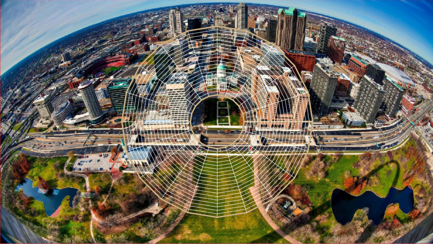
}Input image with transformation mesh shown below:

Output image shown below:
-
Equisolid Configuration file content as follows:
{
    "inputRes": [
        1920,
        1080
    ],
    "param": {
        "fov": 160,
        "diameter": 1080,
        "offsetX": 0,
        "offsetY": 0
    },
    "outputRes": [
        1920,
        1080
    ],
    "transformations": [
        {
            "transformation": "Panoramic",
            "position": [
                0,
                0,
                1920,
                1080
            ],
            "param": {
                "strength": 1,
                "strengthY": 1,
                "rotation": 0
            },
            "ptz": [
                0,
                0,
                1
            ],
            "roi": {
                "x": 0,
                "y": 0,
                "w": 1920,
                "h": 1080
            }
        }
    ],
    "mode": "semiplanar420","eccMode": "eccDisabled",
    "colourspace": "yuv"
}
Input image with transformation grid as follows:

Output image as follows:

-
Equisolid (cylinder) Configuration file content as follows:
{
    "inputRes": [
        1920,
        1080
    ],
    "param": {
        "fov": 160,
        "diameter": 1080,
        "offsetX": 0,
        "offsetY": 0
    },
    "outputRes": [
        1920,
        1080
    ],
    "transformations": [
        {
            "transformation": "Stereographic",
            "position": [
                0,
                0,
                1920,
                1080
            ],
            "param": {
                "strength": 1,
                "rotation": 0
            },
            "ptz": [
                0,
                0,
                1
            ],
            "roi": {
                "x": 0,
                "y": 0,
                "w": 1920,
                "h": 1080
            }
        }
    ],
    "mode": "semiplanar420",
    "eccMode": "eccDisabled",
    "colourspace": "yuv"
}
Input image with transformation grid as follows:
Output image as follows:

-
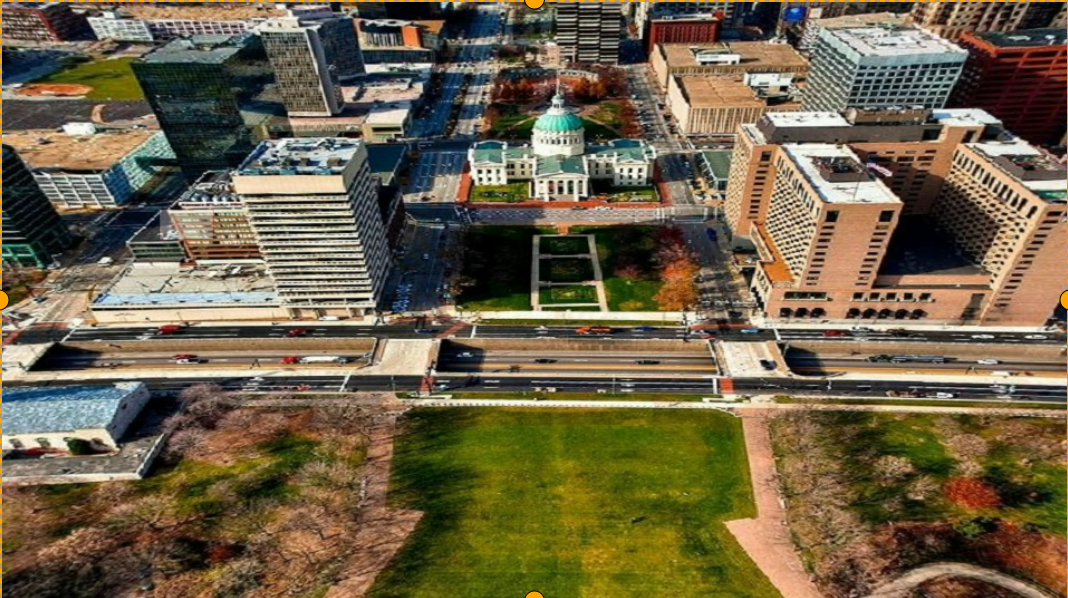
Equidistant Configuration file content as follows:
{
    "inputRes": [
        1920,
        1080
    ],
    "param": {
        "fov": 160,
        "diameter": 1080,
        "offsetX": 0,
        "offsetY": 0
    },
    "outputRes": [
        1920,
        1080
    ],
    "transformations": [
        {
            "transformation": "Universal",
            "position": [
                0,
                0,
                1920,
                1080
            ],
            "param": {
                "azimuth": 0,
                "elevation": 0,
                "rotation": 0,
                "fovWidth": 90,
                "fovHeight": 90,
                "keepRatio": 0,
                "cylindricityX": 1,
                "cylindricityY": 1
            },
            "ptz": [
                0,
                0,
                1
            ],
            "roi": {
                "x": 0,
                "y": 0,
                "w": 1920,
                "h": 1080
            }
        }
    ],
    "mode": "semiplanar420",
    "eccMode": "eccDisabled",
    "colourspace": "yuv"
}
Input image with transformation grid as follows:
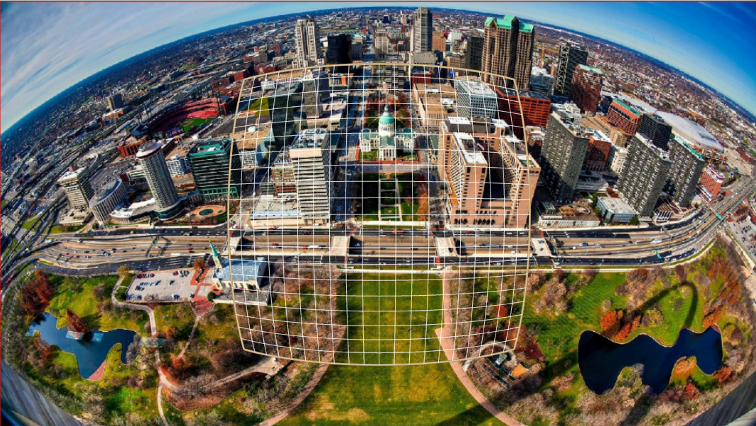
Output image as follows:
-
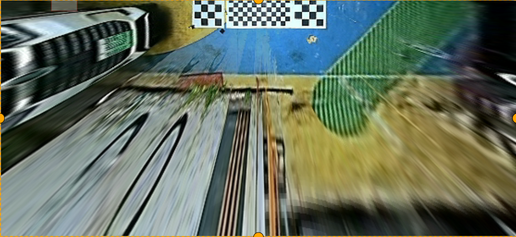
Custom Input resolution: 1280x720, output resolution: 560x258. Configuration file content as follows:
{
    "inputRes": [
        1280,
        720
    ],
    "param": {
        "fov": 192,
        "diameter": 720,
        "offsetX": 0,
        "offsetY": 0
    },
    "outputRes": [
        560,
        258
    ],
    "transformations": [
        {
            "transformation": "Custom",
            "position": [
                0,
                0,
                560,
                258
            ],
            "ptz": [
                0,
                0,
                1
            ],
            "roi": {
                "x": 0,
                "y": 0,
                "w": 0,
                "h": 0
            },
            "param": {
                "customTransformation": "/path_to/camera_0_gdc_config_3.1.txt"
            }
        }
    ],
    "mode": "semiplanar420",
    "eccMode": "eccDisabled",
    "colourspace": "yuv"
}
Input image with transformation grid as follows:
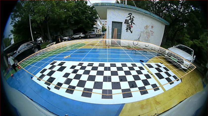
Output image as follows:
-
Keystone + dewarping Configuration file content as follows:
{"inputRes": [
        1920,
        1080
    ],
    "param": {
        "fov": 180,
        "diameter": 1080,
        "offsetX": 0,
        "offsetY": 0
    },
    "outputRes": [
        1920,
        1080
    ],
    "transformations": [
        {
            "transformation": "Dewarp_keystone",
            "position": [
                0,
                0,
                1920,
                1080
            ],
            "param": {
                "left_base_angle": 90,
                "right_base_angle": 90,
                "azimuth": 0,
                "elevation": 0,
                "rotation": 0,
                "fovWidth": 90,
                "fovHeight": 90,
                "keepRatio": 0,
                "cylindricityX": 1,
                "cylindricityY": 1
            },
            "ptz": [
                0,
                0,
                1
            ],
            "roi": {
                "x": 0,
                "y": 0,
                "w": 1920,
                "h": 1080
            }
        }
    ],
    "mode": "semiplanar420",
    "eccMode": "eccDisabled",
    "colourspace": "yuv"
}
Input image with transformation grid is shown below:

Output image is shown below:

GDC Bin Related API Reference
The following APIs are used for GDC BIN generation. For GDC module control APIs, refer to the HBN API.
-
hb_vio_gen_gdc_cfg
【Function Declaration】
int32_t hb_vio_gen_gdc_cfg(param_t *gdc_parm, window_t *wnds, uint32_t wnd_num, void **cfg_buf, uint64_t *cfg_size)
【Parameter Description】
- [IN] param_t *gdc_parm: GDC-related parameters, including resolution, format, etc.
- [IN] window_t *wnds: Parameters for internal regions within GDC.
- [IN] uint32_t wnd_num: Number of windows.
- [OUT] uint32_t **cfg_buf: Generated GDC configuration BIN buffer, allocated internally.
- [OUT] uint64_t *cfg_size: Size of the GDC configuration BIN file.
【Return Value】
- Success: E_OK: Success
- Failure: E_NOT_OK: Fail, return error code; range: [-10000, -1]
【Function Description】 Generates the BIN file required for GDC module operation.
-
hb_vio_set_gdc_cfg
【Function Declaration】
int32_t hb_vio_set_gdc_cfg(uint32_t pipeline_id, uint32_t *cfg_buf, uint64_t cfg_size)
【Parameter Description】
- [IN] uint32_t pipeline_id: Pipeline ID; software channel ID; range: [0, 23], default: 0;
- [IN] cfg_buf: Configuration buffer of the GDC BIN file.
- [IN] cfg_size: Size of the GDC BIN file.
【Return Value】
- Success: E_OK: Success
- Failure: E_NOT_OK: Fail, return error code; range: [-10000, -1]
【Function Description】
Sets the GDC module's configuration BIN.
-
hb_vio_free_gdc_cfg
【Function Declaration】
void hb_vio_free_gdc_cfg(uint32_t *cfg_buf)
【Parameter Description】
- [IN] uint32_t* cfg_buf: Buffer of the GDC BIN file.
【Return Value】
- NONE
【Function Description】
Frees the buffer allocated for the GDC module's configuration BIN.
GDC Bin Related Parameter Descriptions
-
typedef struct param_t
Name Type Min Value Max Value Default Description Required format frame_format_t Image format to be processed Yes in resolution_t Actual input image resolution Yes out resolution_t Actual output image resolution Yes x_offset int32_t 0 0 Pixel offset of the input region along the x-axis Yes y_offset int32_t 0 0 Pixel offset of the input region along the y-axis Yes diameter int32_t Pixel diameter of the circular input area containing the actual fisheye image within the rectangular input image. For some cameras, this circular image area may be larger or smaller than the rectangular canvas (sometimes cropped). Typically, diameter should match input.height. Yes fov double 0 Field of view defining the visible angle of the input image, affecting the curvature of the source mesh. Larger FOV results in greater perspective distortion. Yes -
typedef enum frame_format frame_format_t
Name Type Min Value Max Value Default Description Required FMT_UNKNOWN enum Unknown format FMT_LUMINANCE enum Not supported FMT_PLANAR_444 enum Not supported FMT_PLANAR_420 enum Not supported FMT_SEMIPLANAR_420 enum NV12 FMT_GDC_MAX enum -
typedef struct resolution_s resolution_t
Name Type Min Value Max Value Default Description Required w uint32_t Width (in pixels) h uint32_t Height (in pixels) -
typedef struct window_t
Name Type Min Value Max Value Default Description Required out_r rect_t Output data size information transform transformation_t 0 6 0 Transformation mode used input_roi_r rect_t ROI region pan int32_t Horizontal target displacement (in pixels) centered on the output image tilt int32_t Vertical target displacement (in pixels) centered on the output image zoom double Target zoom factor strengthX double Non-negative transformation strength parameter in the X direction strengthY double Non-negative transformation strength parameter in the Y direction angle double Rotation angle of the principal projection axis around itself elevation double Angle specifying the principal projection axis azimuth double Angle specifying the principal projection axis, measured clockwise from north keep_ratio int32_t Maintain the same stretch intensity in both horizontal and vertical directions FOV_h double Vertical dimension of the output field of view, expressed in degrees FOV_w double Horizontal dimension of the output field of view, expressed in degrees cylindricity_y double Cylindricity level of the target projection shape in the vertical direction cylindricity_x double Cylindricity level of the target projection shape in the horizontal direction custom_file[128] char Custom transformation description file used in custom mode custom custom_tranformation_t Transformation information in custom mode trapezoid_left_angle double Left acute angle between the trapezoid base and its slanted side trapezoid_right_angle double Right acute angle between the trapezoid base and its slanted side check_compute uint8_t Currently unused -
typedef struct rect_s rect_t
Name Type Min Value Max Value Default Description Required x int32_t Starting X coordinate y int32_t Starting Y coordinate w int32_t Width h int32_t Height -
typedef enum gdc_transformation transformation_t
Name Type Min Value Max Value Default Description Required PANORAMIC enum Panoramic transformation CYLINDRICAL enum NA STEREOGRAPHIC enum Same as distortion correction and panoramic transformation, but the output image is a cylindrical panorama instead of a planar image UNIVERSAL enum Equidistant transformation CUSTOM enum User-defined transformation; allows customization of the transformation mesh AFFINE enum Linear transformation DEWARP_KEYSTONE enum Non-equidistant transformation selectable relative to equidistant transformation; equidistant transformation is a special case of this -
typedef struct point_s point_t
Name Type Min Max Default Description Required x double x coordinate y double y coordinate -
typedef struct custom_tranformation_s custom_tranformation_t
Name Type Min Max Default Description Required full_tile_calc uint8_t Whether to enable tile-based calculation; if enabled, libgdcbin performs additional min/max calculations per tile. More tiles yield higher precision and better results but increase bin generation time. tile_incr_x uint16_t Tile increment in x direction tile_incr_y uint16_t Tile increment in y direction w int32_t Number of points in the horizontal direction of the custom transformation grid h int32_t Number of points in the vertical direction of the custom transformation grid centerx double Center along the x-axis, typically half the number of horizontal coordinate points centery double Center along the y-axis, typically half the number of vertical coordinate points *points point_t Sequence of transformation points defined in config.txt; total count =w * h
STITCH
Introduction
Stitch is a configurable image stitching computation unit capable of blending and stitching multiple images together. It is primarily used for 360-degree surround-view image stitching in automated parking scenarios. Stitch operates based on Regions of Interest (ROIs). Each ROI can perform alpha-beta blending between two source images and write the result into a designated ROI of the target image. This blending approach ensures smoother transitions at stitching boundaries. Additionally, Stitch supports gain adjustment for Y, U, and V channels separately, enabling brightness and chrominance balancing between source images to further enhance stitching quality. Moreover, Stitch allows users to input custom per-pixel alpha-beta weight values, enabling various blending effects such as background blur or image watermarking.
The Stitch hardware supports maximum input and output resolutions of 4096x4096.
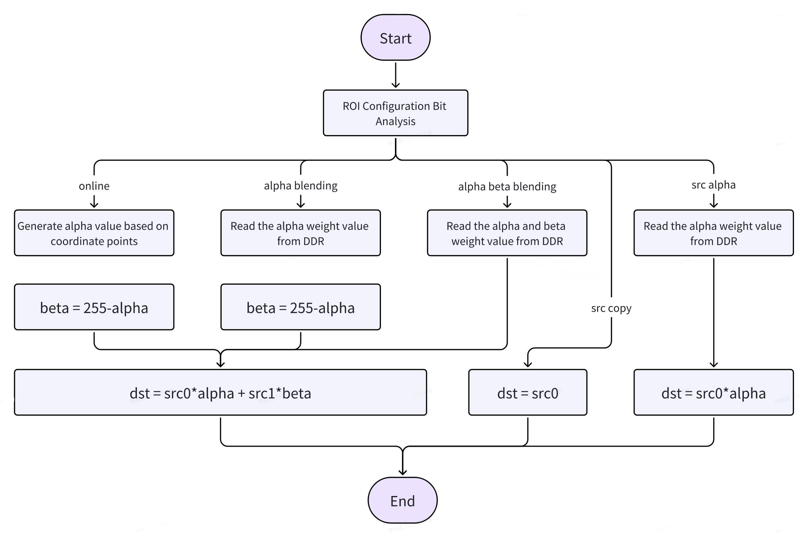
Hardware Operating Modes
- Online Blending: No LUT table input required; hardware automatically performs blending and stitching. Requires ROI width = height (w = h). In this mode, the hardware automatically calculates alpha and beta weights for each pixel based on configured parameters such as transition zone width and direction.
- Alpha Blending: Requires an alpha LUT table. The hardware reads alpha weight values from DDR memory for weighted blending. The alpha LUT stores the alpha weight for each pixel within the ROI. For each pixel, the hardware reads Y, UV, and alpha values separately for weighted blending.
- Alpha-Beta Blending: Requires both alpha and beta LUT tables. The hardware reads alpha and beta weight values from DDR for weighted blending.
- Src Copy: No LUT table required; hardware directly copies src0.
- Src Alpha Copy: Requires an alpha LUT table; hardware reads alpha weights from DDR and blends src0 accordingly.
Here, the "LUT table" refers to the buffer storing blending weight parameters.
Hardware Stitching Diagram
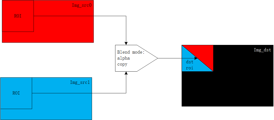
By using the two source ROIs shown in the image with different blend modes, the corresponding ROI output results are generated.
Stitching Scheme Overview
The hardware stitching function can merge and blend multiple images into a single output image. Designed flexibly, it uses ROIs as the basic processing unit and employs the alpha blending algorithm. Different ROI partitions and configurations can be defined via configuration parameters to generate various stitching schemes. Additionally, LUT tables are used to optimize transition zones during stitching. In autonomous driving and ADAS Automated Parking Assist (APA) scenarios, this hardware can stitch four IPM (Inverse Perspective Mapping) images—already distortion-corrected from four cameras—into a single 360-degree surround-view image for parking space detection, allowing users to easily view parking lines and surroundings.
Typical Scenario
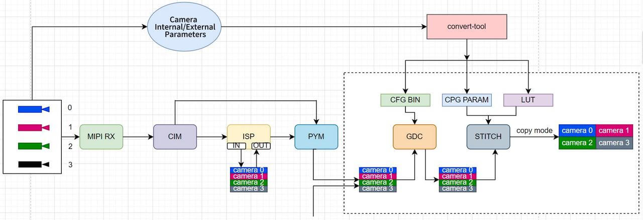
In an APA scenario with four surround-view cameras, GDC fetches four back-projected images and reference points (CFG BIN) from DDR, outputs four IPM images after distortion correction, and then uses the STITCH hardware module with a pre-defined stitching configuration (CPG PARAM) to generate a bird's-eye-view output.
Placement Layout

- The four IPM images are placed at specified locations in the output buffer using copy mode.
- Non-overlapping regions can use direct copy mode.
- Overlapping ROI regions use Alpha Blend mode for seamless fusion.
LUT Table
The LUT table stores alpha/beta blending coefficients (similar to weight values). Each ROI must generate corresponding per-pixel blending coefficients ranging from 0 to 255, which are sequentially stored in the LUT table memory. When an ROI uses alpha or beta blending mode, these parameters are used for fusion.
For example, in the LUT generation described in the "Coordinate Parameter Example" section:
ROI-0/1: 256×512, ROI-2/3: 560×256, ROI-4/5: 256×218, ROI-6/7: 256×186
LUT: ROI-0 + ROI-1 + ROI-2 + ROI-3 + ROI-4 + ROI-5 + ROI-6 + ROI-7
Currently, the LUT table can be generated using the convert_tool.
Coordinate Parameter Example
ROI partitioning for hardware stitching is directly related to camera mounting positions. Currently, ROI partitions can be generated using the convert-tool. The figure below shows an example of coordinate points for each ROI region.

| ROI | Range | SRC0 | Start | Size | SRC1 | Start | Size | Dest Start | Mode |
|---|---|---|---|---|---|---|---|---|---|
| 0 | Full left view | Left (frame0) | (0,0) | -256,512 | / | / | / | (0,40) | Direct Copy |
| 1 | Full right view | Right (frame2) | (0,0) | -256,512 | / | / | / | (304,40) | Direct Copy |
| 2 | Full rear view | Rear (frame3) | (0,0) | -560,256 | / | / | / | (0,366) | Direct Copy |
| 3 | Full front view | Front (frame1) | (0,0) | -560,256 | / | / | / | (0,0) | Direct Copy |
| 4 | Overlap: Left & Front | Left (frame0) | (0,0) | -256,218 | Front (frame1) | (0,40) | -256,218 | (0,40) | AlphaBlend |
| 5 | Overlap: Right & Front | Right (frame2) | (0,0) | -256,218 | Front (frame1) | (304,40) | -256,218 | (304,40) | AlphaBlend |
| 6 | Overlap: Left & Rear | Left (frame0) | (0,366) | -256,186 | Rear (frame3) | (0,0) | -256,186 | (0,366) | AlphaBlend |
| 7 | Overlap: Right & Rear | Right (frame2) | (0,366) | -256,186 | Rear (frame3) | (304,0) | -256,218 | (-304,366) | AlphaBlend |
LPWM
Overview of LPWM
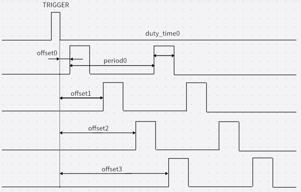
LPWM is a signal source similar to PWM, typically used to trigger sensor exposure in the camsys system. LPWM itself requires an external trigger. Upon receiving a trigger signal, it outputs a square wave based on the configured parameters such as period, high-time, and offset, with a frequency ranging from 1 Hz to 500 kHz, an effective high-level duration from 0 μs to 4095 μs, and a default precision of 1 μs.
The S100 integrates 3 LPWM chips, each containing 4 LPWM channels. Configuration should be performed according to the actual hardware connections.
The camera hardware synchronization function of the S100 is mainly implemented by the LPWM module. It supports multiple trigger sources for the S100 and generates multi-channel configurable PWM signals for external cameras (which can be forwarded via SerDes), thereby achieving synchronization between the trigger source and cameras, as well as synchronization among multiple cameras.
LPWM Configuration Items
-
trigger_mode [0, 1]: LPWM trigger mode
- 0: Internal software trigger
- 1: External trigger
-
trigger_source [0, 10]: LPWM trigger source. To use an external trigger source, set
trigger_mode = 1. In typical scenarios, use 0 with a default trigger period of 1 second.
| trigger_source Value | Corresponding Trigger Source |
|---|---|
| 0 | aon_rtc_pps |
| 1 | reserve |
| 2 | pps0 |
| 3 | pps1 |
| 4 | pps2 |
| 5 | reserve |
| 6 | pcie0_ptm_pps |
| 7 | pcie1_ptm_pps |
| 8 | acore_eth0_pps |
| 9 | acore_eth1_pps |
| 10 | mcu_eth_pps |
- period [2, 1000000) μs: Period of the LPWM output square wave.
- offset [0, 1000000) μs: Offset time of the first waveform within each trigger cycle. Must be smaller than
period. - duty_time [0, 4096) μs: Effective high-level duration of the LPWM output waveform. Must be smaller than
period. - threshold [0, 65535] μs: Threshold for slow synchronization. Advanced feature; can usually be ignored.
- adjust_step [0, 15]: Adjustment step per cycle.
adjust_time = 2^adjust_step. Advanced feature; can usually be ignored.
LPWM Configuration Calculation
The LPWM trigger source is typically PPS with a common period of 1 second.
After receiving a trigger signal, LPWM first delays by the configured offset, then outputs continuous square waves. The waveform period and effective high-level duration are determined by configuration. When the next trigger arrives, the delay and waveform generation repeat.
The offset setting depends on the sensor fps:
- If 1 second cannot be divided evenly by fps,
offsetmust be configured. - Otherwise, set
offset = 0.
Example: 30 fps sensor
period = 1 s / fps = 33333 μs- After 30 frames, the total time is 999,990 μs, leaving a 10 μs gap until the next PPS trigger.
- Therefore,
offsetshould be set to 10 μs (minimum 10 μs, maximumperiod - duty_timeμs). To be safe, add 1 to the calculated offset; otherwise, LPWM will output 31 pulses within 1 second.
Due to hardware or peripheral differences, PPS may fall in the high-level region.
If slow synchronization is disabled or completed, LPWM must finish the current high-level period before entering the next trigger cycle (and recalculating offset).
This may result in fewer waveforms than expected per trigger cycle, causing the sensor frame rate to deviate from the target in exposure-synchronized mode.
In such cases, increase offset appropriately to ensure PPS always falls in the low-level region and outputs the expected waveform.
Period = 1000000 / fps
Offset = 1000000 - Period * fps + 1
Recommended Configurations
| Usage Scenario | trigger_source | trigger_mode | duty_time | offset | period |
|---|---|---|---|---|---|
| All 30 fps | 8(eth0)/9(eth1) | 1 | 100 | 11 | 33333 |
| All 25 fps | 8(eth0)/9(eth1) | 1 | 100 | 11 | 40000 |
| 12.5/25 fps | 8(eth0)/9(eth1) | 1 | 100 | 11 | 80000/40000 |
| 30/10 fps | 8(eth0)/9(eth1) | 1 | 100 | 11 | 33333/100000 |
Other Notes
When the MCU RTC function is enabled, the CIM hardware automatically latches the timestamp corresponding to the LPWM trigger signal.
Software synchronizes this timestamp with global_time and provides it to the user.
When the sensor operates in exposure synchronization mode, this timestamp represents the start time of sensor exposure triggering.
When the sensor is in frame-synchronized output or unsynchronized mode, the sensor exposure start time is not related to the LPWM signal. In other words, there is no correlation between CIM frame start (tv) and LPWM trigger (trig_tv) time. In this case, the timestamp has no reference value and can be ignored.
In actual use, ensure PPS stably falls in the low-level region by appropriately increasing offset based on debugging results.
Data Flow and Performance Metrics
After RDK-S100 connects to cameras, the data flows through subsequent processing modules as shown below:
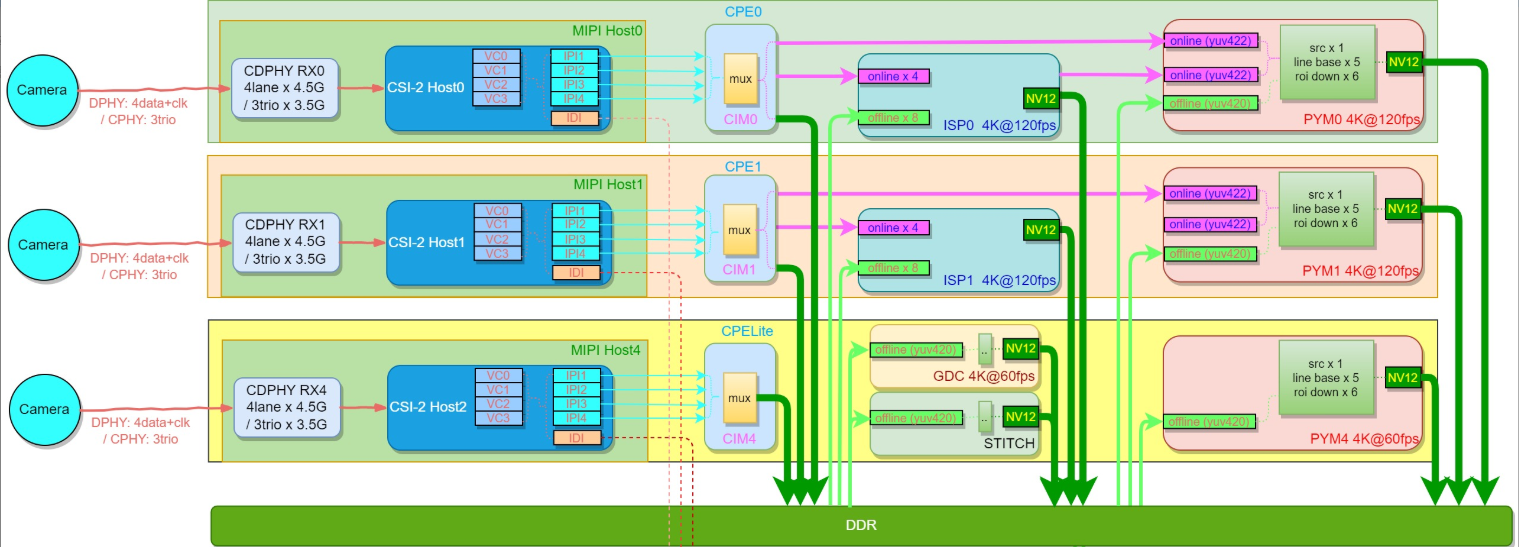
- MIPI RX: 3 CDPHY lanes, each supporting either DPHY up to 4.5 Gbps/lane × 4 lanes or CPHY up to 3.5 Gbps/trio × 3 trios. Each lane supports 4 virtual channels (VCs), theoretically allowing up to 12 camera inputs.
| RDK-S100 software is expected to support up to 6 cameras: RX4 can connect up to 4 cameras via SerDes, while RX0 and RX1 each connect to 1 camera. For non-standard configurations, please consult an FAE for confirmation. |
|---|
The commercial version offers more comprehensive feature support, deeper hardware capability exposure, and exclusive customization options. To ensure compliance and secure delivery, access to the commercial version will be granted through the following process.
Commercial Version Access Process:
- Complete a questionnaire: Submit your organization’s information and intended use case.
- Sign an NDA: We will contact you based on your submission to finalize and sign a Non-Disclosure Agreement.
- Content release: After NDA execution, we will provide access to commercial documentation via a private channel.
If you wish to access the commercial version, please complete the questionnaire below. We will contact you within 3–5 business days:
Questionnaire link: https://horizonrobotics.feishu.cn/share/base/form/shrcnJQBMIkRm6K79rjXR0hr0Fg
-
CIM: Receives input from RX and can output online to ISP0/ISP1 (RAW) or PYM0/PYM1 (YUV), or store offline to DDR for subsequent modules to access via DDR.
-
ISP: Two ISP units, each supporting 4 online + 8 offline inputs. Each ISP can handle up to 2×4K@60fps.
-
PYM: Three PYM units—PYM0/PYM1 are full-featured and support both online/offline modes, while PYM4 supports offline only, with 4K@60fps processing capability.
-
GDC: One GDC unit, supporting offline mode only, with 4K@60fps processing capability.
| CIM | ISP0 / ISP1 | PYM0 / PYM1 | PYM4 | GDC | YNR | STITCH | |
|---|---|---|---|---|---|---|---|
| Per-frame latency at 1080p | 3.7151 ms | 1.8616 ms | 2.2373 ms | 2.7616 ms | 3.7447 ms | 1.7774 ms | 1.5739 ms |
| Per-frame latency at 4K | 14.8606 ms | 7.4467 ms | 7.1356 ms | 10.7018 ms | 15.0624 ms | 7.1096 ms | 5.7349 ms |
Camsys Input Capability
The S100 Camsys hardware theoretically supports up to 8×4K RAW @30fps + 4×1536p YUV @30fps.
Validated maximum input configurations include:
- 3×4K RAW (3840×2160) @30fps + 9×1280p RAW (1920×1280) @30fps;
- 3×4K RAW (3840×2160) @30fps + 5×1280p RAW (1920×1280) @30fps + 4×1536p YUV (1920×1536) @30fps.
Supported Sensors
| Type | Sensor Name | Notes |
|---|---|---|
| MIPI sensor | IMX219 | raw10, 1080p |
| GMSL sensor | 0820c | yuv, 4K & 1080p |
| OVX3C | raw12, 1280P | |
| OVX8B | raw12, 4K |
Camera API
| Note: This section describes APIs based on the HBN architecture, not V4L2. |
|---|
Module Description
The RDK-S100 HBN Camera consists of three components: Camera Sensor, Deserializer, and Serializer. The Serializer encapsulates the MIPI TX functionality.
Each component provides attach and detach interfaces and supports binding/unbinding with VIN. For example, binding a camera to VIN determines which MIPI RX and I2C controller on the SoC the camera uses, followed by sensor initialization.
API Reference
- hbn_camera_create
【Function Declaration】
int32_t hbn_camera_create(camera_config_t *cam_config, camera_handle_t *cam_fd)
【Parameters】
[IN] camera_config_t *cam_config: Pointer to the configuration structure for the camera to be set up.
[OUT] camera_handle_t *cam_fd: Returns a file descriptor (handle) for operating the camera based on the provided configuration.
【Return Value】
Success: RET_OK (0)
Failure: Negative error code
【Function Description】
Creates a camera handle based on the configuration provided in camera_config_t.
【Notes】
The API will check the sensor lib. If the sensor driver code does not comply with the HBN framework specification, an error will be reported during the check.
The API will check cam_config. If the configuration does not match the IP hardware capabilities, an error will be reported during the check.
- hbn_camera_destroy
【Function Declaration】
int32_t hbn_camera_destroy(camera_handle_t cam_fd)
【Parameter Description】
[IN] camera_handle_t cam_fd: The camera operation handle created by hbn_camera_create;
【Return Value】
Success: RET_OK 0
Failure: Negative error code for exceptions
【Function Description】
Destroy the corresponding software resources based on the camera handle.
【Notes】
hbn_camera_destroy must be used in pair with hbn_camera_create.
hbn_camera_destroy will release the sensor lib. After execution, the sensor will no longer be accessible.
Internally, hbn_camera_destroy calls hbn_camera_detach_from_vin, which triggers the sensor stream stop operation. Therefore, hbn_camera_destroy must be called before hbn_vflow_destroy.
- hbn_camera_attach_to_vin
【Function Declaration】
int32_t hbn_camera_attach_to_vin(camera_handle_t cam_fd, vpf_handle_t vin_fd)
【Parameter Description】
[IN] camera_handle_t cam_fd: Camera handle created by hbn_camera_create;
[IN] vpf_handle_t vin_fd: VIN node handle created by the hbn_vnode_open interface.
【Return Value】
Success: RET_OK 0
Failure: Negative error code for exceptions
【Function Description】
Bind the camera and VIN node together within the VPF framework using their respective handles, and perform hardware initialization for the camera.
【Notes】
The same camera must not repeatedly call hbn_camera_attach_to_vin; otherwise, an "attach error" will be reported.
- hbn_camera_detach_from_vin
【Function Declaration】
int32_t hbn_camera_detach_from_vin(camera_handle_t cam_fd)
【Parameter Description】
[IN] camera_handle_t cam_fd: Camera handle created by hbn_camera_create;
【Return Value】
Success: RET_OK 0
Failure: Negative error code for exceptions
【Function Description】
Unbind the camera from the VIN node and perform de-initialization.
【Notes】
hbn_camera_detach_from_vin must be used in pair with hbn_camera_attach_to_vin.
hbn_camera_destroy internally calls hbn_camera_detach_from_vin, so after calling hbn_camera_destroy, there is no need to explicitly call hbn_camera_detach_from_vin.
- hbn_camera_attach_to_deserial
【Function Declaration】
int32_t hbn_camera_attach_to_deserial(camera_handle_t cam_fd, deserial_handle_t des_fd, camera_des_link_t link)
【Parameter Description】
[IN] camera_handle_t cam_fd: Camera handle created by hbn_camera_create;
[IN] deserial_handle_t des_fd: Deserializer handle created by hbn_deserial_create;
[IN] camera_des_link_t link: The linking method between camera and deserializer, determined by which link the camera is connected to.
【Return Value】
Success: RET_OK 0
Failure: Negative error code for exceptions
【Function Description】
Bind the camera and deserializer using their handles, and perform hardware initialization for both the deserializer and camera.
【Notes】
This interface should only be called when a deserializer exists in the hardware.
After calling hbn_camera_attach_to_deserial, there is no need to call hbn_camera_attach_to_vin; instead, the deserializer will be bound to the VIN node.
- hbn_camera_detach_from_deserial
【Function Declaration】
int32_t hbn_camera_detach_from_deserial(camera_handle_t cam_fd)
【Parameter Description】
[IN] camera_handle_t cam_fd: Camera handle created by hbn_camera_create;
【Return Value】
Success: RET_OK 0
Failure: Negative error code for exceptions
【Function Description】
Unbind the camera from the deserializer and perform de-initialization.
【Notes】
hbn_camera_detach_from_deserial must be used in pair with hbn_camera_attach_to_deserial.
Before calling this API, hbn_deserial_detach_from_vin must be called first.
- hbn_camera_start
【Function Declaration】
int32_t hbn_camera_start(camera_handle_t cam_fd)
【Parameter Description】
[IN] camera_handle_t cam_fd: Camera handle created by hbn_camera_create;
【Return Value】
Success: RET_OK 0
Failure: Negative error code for exceptions
[Function Description]
Configure camera registers and start streaming.
【Notes】
If the camera handle has been attached to a vflow, this interface may not need to be called. If it is called, hbn_vflow_start must be called first, followed by hbn_camera_start.
- hbn_camera_stop
【Function Declaration】
int32_t hbn_camera_stop(camera_handle_t cam_fd)
【Parameter Description】
[IN] camera_handle_t cam_fd: Camera handle created by hbn_camera_create;
【Return Value】
Success: RET_OK 0
Failure: Negative error code for exceptions
【Function Description】
Stop the camera stream.
【Notes】
Must be used in pair with hbn_camera_start.
- hbn_camera_reset
【Function Declaration】
int32_t hbn_camera_reset(camera_handle_t cam_fd)
【Parameter Description】
[IN] camera_handle_t cam_fd: Camera handle created by hbn_camera_create;
【Return Value】
Success: RET_OK 0
Failure: Negative error code for exceptions
【Function Description】
Reset the sensor by re-initializing it.
【Notes】
If this API is called before attaching the camera to VIN, sensor initialization will be performed via the camera_attach_to_vin interface to achieve the reset effect. If this API is called after attaching the camera to VIN, the sequence sensor_stop → sensor_deinit → sensor_init → sensor_start will be executed to reset the sensor.
- hbn_camera_change_fps
【Function Declaration】
int32_t hbn_camera_change_fps(camera_handle_t cam_fd, int32_t fps)
【Parameter Description】
[IN] camera_handle_t cam_fd: Camera handle created by hbn_camera_create;
[IN] int32_t fps: Output frame rate of the sensor;
【Return Value】
Success: RET_OK 0
Failure: Negative error code for exceptions
【Function Description】
Dynamically switch the sensor frame rate.
【Notes】
This feature requires implementing the corresponding callback function dynamic_switch_fps in the sensor library.
- hbn_camera_read_register
【Function Declaration】
int32_t hbn_camera_read_register(camera_handle_t cam_fd, camera_reg_type_t type,
uint32_t reg_addr)
【Parameter Description】
[IN] camera_handle_t cam_fd: Camera handle created by hbn_camera_create;
[IN] camera_reg_type_t type: Type of sensor register to read;
[IN] uint32_t reg_addr: Register address;
【Return Value】
Success: RET_OK 0
Failure: Negative error code for exceptions
【Function Description】
Read the value of a camera register.
【Notes】
None
- hbn_camera_get_handle
【Function Declaration】
camera_handle_t hbn_camera_get_handle(vpf_handle_t vin_fd, int32_t camera_index)
【Parameter Description】
[IN] vpf_handle_t vin_fd: File descriptor (fd) of the VIN node;
[IN] int32_t camera_index: Port index of the camera;
【Return Value】
Success: RET_OK 0
Failure: Negative error code for exceptions
【Function Description】
Obtain the corresponding camera handle via the VIN node handle or camera port index.
【Notes】
None
- hbn_camera_init_cfg
【Function Declaration】
int32_t hbn_camera_init_cfg(const char *cfg_file)
【Parameter Description】
[IN] const char *cfg_file: Path to the camera configuration file (JSON format);
【Return Value】
Success: RET_OK 0
Failure: Negative error code for exceptions
【Function Description】
Create a camera handle and a deserializer handle based on the provided configuration and bind them together.
【Notes】
This API creates cameras by parsing a JSON configuration file, which differs from the non-JSON approach used in the sample code. For further details, please consult your FAE.
The commercial version offers more comprehensive feature support, deeper hardware capability exposure, and exclusive customization options. To ensure compliance and secure delivery, access to the commercial version will be granted through the following process:
Commercial Version Access Procedure:
- Complete a questionnaire: Submit basic information about your organization and intended use case.
- Sign a Non-Disclosure Agreement (NDA): We will contact you based on your submission, and both parties will sign the NDA upon mutual confirmation.
- Content release: After the NDA is signed, we will provide access to the commercial version materials through a private channel.
If you wish to obtain the commercial version, please fill out the questionnaire below. We will contact you within 3–5 business days:
Questionnaire link: https://horizonrobotics.feishu.cn/share/base/form/shrcnJQBMIkRm6K79rjXR0hr0Fg
- hbn_deserial_create
【Function Declaration】
int32_t hbn_deserial_create(deserial_config_t *des_config, deserial_handle_t
*des_fd)
【Parameter Description】
[IN] deserial_config_t *des_config: Pointer to the deserializer configuration parameter structure;
[OUT] deserial_handle_t *des_fd: Deserializer handle created according to the configuration;
【Return Value】
Success: RET_OK 0
Failure: Negative error code for exceptions
【Function Description】
Create a deserializer handle based on the provided configuration.
【Notes】
This API should only be called when a hardware deserializer is present.
This API validates the deserializer configuration; an error will be returned if the configuration exceeds allowed limits.
This API also checks the deserializer library; an error will be returned if it does not comply with HBN architecture specifications.
- hbn_deserial_destroy
【Function Declaration】
int32_t hbn_deserial_destroy(deserial_handle_t des_fd)
【Parameter Description】
[IN] deserial_handle_t des_fd: Deserializer handle created by hbn_deserial_create;
【Return Value】
Success: RET_OK 0
Failure: Negative error code for exceptions
【Function Description】
Destroy the corresponding software resources based on the deserializer handle.
【Notes】
hbn_deserial_destroy must be used in pair with hbn_deserial_create.
- hbn_deserial_attach_to_vin
【Function Declaration】
int32_t hbn_deserial_attach_to_vin(deserial_handle_t des_fd, camera_des_link_t
link, vpf_handle_t vin_fd)
【Parameter Description】
[IN] deserial_handle_t des_fd: Deserializer handle, created by hbn_deserial_create;
[IN] camera_des_link_t link: Link index of the deserializer;
[IN] vpf_handle_t vin_fd: VIN node handle to bind to;
【Return Value】
Success: RET_OK 0
Failure: Negative error code for exceptions
【Function Description】
Bind the deserializer to a VIN node.
【Notes】
If the hardware includes a deserializer, the camera should be bound to the deserializer, and the deserializer should be bound to the VIN node.
- hbn_deserial_detach_from_vin
【Function Declaration】
int32_t hbn_deserial_detach_from_vin(deserial_handle_t des_fd, camera_des_link_t link)
【Parameter Description】
[IN] deserial_handle_t des_fd: Deserializer handle, created by hbn_deserial_create;
[IN] camera_des_link_t link: Link index of the deserializer;
【Return Value】
Success: RET_OK 0
Failure: Negative error code for exceptions
【Function Description】
Unbind the deserializer from the VIN node.
【Notes】
hbn_deserial_detach_from_vin must be used in pair with hbn_deserial_attach_to_vin.
- hbn_txser_create
【Function Declaration】
int32_t hbn_txser_create(txser_config_t *txs_config, txser_handle_t *txs_fd)
【Parameter Description】
[IN] txser_config_t *txs_config: Pointer to the TX serializer configuration structure;
[OUT] txser_handle_t *txs_fd: TX serializer handle created according to the configuration;
【Return Value】
Success: RET_OK 0
Failure: Negative error code for exceptions
【Function Description】
Create a TX serializer handle based on the provided configuration.
【Notes】
This API should only be called when the hardware includes a serializer.
The API validates the TX serializer configuration; if the configuration exceeds allowed ranges, an error will be returned.
The API also checks the TX serializer library; if it does not comply with HBN architecture specifications, an error will be returned.
- hbn_txser_destroy
【Function Declaration】
int32_t hbn_txser_destroy(txser_handle_t txs_fd)
【Parameter Description】
[IN] txser_handle_t txs_fd: TX serializer handle, created by hbn_txser_create;
【Return Value】
Success: RET_OK 0
Failure: Negative error code for exceptions
【Function Description】
Destroy software resources associated with the TX serializer handle.
【Notes】
This API should only be called when the hardware includes a serializer.
hbn_txser_destroy must be used in pair with hbn_txser_create.
- hbn_txser_attach_to_vin
【Function Declaration】
int32_t hbn_txser_attach_to_vin(txser_handle_t txs_fd, camera_txs_csi_t csi, vpf_handle_t vin_fd)
【Parameter Description】
[IN] txser_handle_t txs_fd: TX serializer handle, created by hbn_txser_create;
[IN] camera_txs_csi_t csi: TX CSI index;
[IN] vpf_handle_t vin_fd: VIN node handle to bind to;
【Return Value】
Success: RET_OK 0
Failure: Negative error code for exceptions
【Function Description】
Bind the TX serializer to a VIN node.
【Notes】
This API should only be called when the hardware includes a serializer.
This API initializes the TX serializer hardware.
If the hardware includes a serializer, the camera should be bound to the TX serializer, and the TX serializer should be bound to the VIN node.
- hbn_txser_detach_from_vin
【Function Declaration】
int32_t hbn_txser_detach_from_vin(txser_handle_t txs_fd, camera_txs_csi_t csi)
【Parameter Description】
[IN] txser_handle_t txs_fd: TX serializer handle, created by hbn_txser_create;
[IN] camera_txs_csi_t csi: TX CSI index;
【Return Value】
Success: RET_OK 0
Failure: Negative error code for exceptions
【Function Description】
Unbind the TX serializer from the VIN node.
【Notes】
hbn_txser_detach_from_vin must be used in pair with hbn_txser_attach_to_vin.
Parameter Description
typedef struct camera_config_s
| Name | Type | Min Value | Max Value | Default Value | Description | Required |
|---|---|---|---|---|---|---|
| name[CAMERA_MODULE_NAME_LEN] | char | – | CAMERA_MODULE_NAME_LEN(108) | – | Camera module name, which must correspond to the sensor library name. For example, if the sensor driver is named libimx219.so, then name should be "imx219". | Yes |
| addr | uint32_t | 0x00 | 0x7f | 0x00 | Sensor device address, typically a 7-bit I2C address. | Yes |
| isp_addr | uint32_t | 0x00 | 0x7f | 0x00 | ISP device address (if any); none by default. | No |
| eeprom_addr | uint32_t | 0x00 | 0x7f | 0x00 | EEPROM device address (if any); none by default. | No |
| serial_addr | uint32_t | 0x00 | 0x7f | 0x00 | SerDes device address (if any); none by default. | No |
| sensor_mode | uint32_t | 1 | 5 | 1 | Sensor operating mode, selectable via enum sensor_mode_e as defined below: | Yes |
| 1: NORMAL_M, linear mode; | ||||||
| 2: DOL2_M, HDR mode combining 2 frames into 1; | ||||||
| 3: DOL3_M, HDR mode combining 3 frames into 1; | ||||||
| 4: DOL4_M, HDR mode combining 4 frames into 1; | ||||||
| 5: PWL_M, HDR mode with internal frame combination in the sensor. | ||||||
| sensor_clk | uint32_t | – | – | 0x00 | Sensor clock configuration; currently unused and reserved for future use. | No |
| gpio_enable | uint32_t | 0 | 0xFFFFFFFF | 0 | Whether to use X5 GPIOs to control camera sensor pins to meet power-up/power-down timing requirements. | Yes |
| Example: Use GPIO to control the sensor's XSHUTDN pin. | ||||||
| Note: Corresponding GPIO numbers must be configured in the device tree (DTS). | ||||||
| 0: Do not use GPIO control; | ||||||
| Non-zero: Enable GPIO control for the sensor, with each bit enabling a specific GPIO. For example, 0x07 enables three GPIOs: [gpio_a, gpio_b, gpio_c]. | ||||||
| gpio_level | uint32_t | 0 | 1 | 0 | If gpio_enable is set, gpio_level bits configure the initial logic levels of the GPIOs controlling sensor pins. The relationship between a GPIO bit and its output sequence is as follows: | Yes |
| 0: Output low first, sleep 1s, then output high; | ||||||
| 1: Output high first, sleep 1s, then output low. | ||||||
| Example: 0x05 = 101 (binary). From bit0 to bit2: gpio_a outputs high then low, gpio_b outputs low then high, gpio_c outputs high then low. | ||||||
| Customize according to the sensor’s power-up timing specification. | ||||||
| bus_select | uint32_t | 0 | 6 | 0 | Selects the I2C bus number for the sensor. Typically fixed by hardware; thus, it is recommended to configure this in the DTS instead of here. | No |
| For details on binding the sensor I2C in DTS, refer to the "Camera Bring-up Guide". | ||||||
| bus_timeout | uint32_t | 0 | – | 0 | I2C timeout configuration. Only required if bus_select is configured. | No |
| fps | uint32_t | 0 | 120 | 0 | Sensor frame rate configuration. | Yes |
| width | uint32_t | 0 | 8192 | 0 | Sensor output image width (in pixels). | Yes |
| height | uint32_t | 0 | 4096 | 0 | Sensor output image height (in pixels). | Yes |
| format | uint32_t | – | – | – | Sensor data format. Common values include: | Yes |
| RAW8: 0x2A; | ||||||
| RAW10: 0x2B; | ||||||
| RAW12: 0x2C; | ||||||
| YUV422 8-bit: 0x1E | ||||||
| flags | uint32_t | 0 | - | 0 | Optional features: diagnostics, recovery, debug, etc. | No |
| extra_mode | uint32_t | 0 | - | 0 | Custom configurations inside each sensor library: mostly used to differentiate modules and toggle features. | Yes |
| config_index | uint32_t | 0 | - | 0 | Custom configurations inside each sensor library: mostly used to differentiate modules and toggle features. | Yes |
| ts_compensate | uint32_t | 0 | - | 0 | Reserved parameter, for future use. | No |
| mipi_cfg | mipi_config_t | - | - | - | MIPI configuration. Set to NULL to automatically fetch configuration from the sensor driver (via get_csi_attr). | Yes |
| calib_lname | char | - | - | - | Path to the sensor calibration library. Default path: /usr/hobot/lib/sensor | Yes |
| sensor_param | char | - | - | - | Sensor custom data. | No |
| iparam_mode | uint32_t | - | - | - | Reserved parameter, for future use. | No |
| end_flag | uint32_t | - | - | - | End-of-structure marker. Default value: CAMERA_CONFIG_END_FLAG | Yes |
typedef struct deserial_config_s
| Name | Type | Min | Max | Default | Description | Required |
|---|---|---|---|---|---|---|
| name | char[CAMERA_MODULE_NAME_LEN] | - | - | - | Deserializer name, e.g., max9296. | Yes |
| addr | uint32_t | 0 | - | - | Deserializer device address. | Yes |
| gpio_enable | uint32_t | 0 | - | - | GPIO operation enable bit, indexed from VCON. | Yes |
| gpio_level | uint32_t | 0 | - | - | GPIO operational state bit, indicating current GPIO status. | Yes |
| gpio_mfp | uint8_t[CAMERA_DES_GPIO_MAX] | 0 | CAMERA_DES_GPIO_MAX | 0x0 | GPIO MFP function selection, used to specify multifunctional GPIO configuration. | Yes |
| bus_select | uint32_t | 0 | - | - | I2C bus selection, indexed from VCON. | Yes |
| bus_timeout | uint32_t | 0 | - | - | I2C timeout setting, in milliseconds. | Yes |
| lane_mode | uint32_t | 0 | - | - | PHY lane mode selection. | Yes |
| lane_speed | uint32_t | 0 | - | - | PHY lane speed configuration. | Yes |
| link_map | uint32_t | 0 | - | - | Mapping configuration between Link and CSI/VC. | Yes |
| link_desp | char[CAMERA_DES_LINKMAX][CAMERA_DES_PORTDESP_LEN] | - | - | - | Configuration descriptions for each Link-connected module, used in multi-process scenarios. | Yes |
| reset_delay | uint32_t | 0 | - | - | Delay time for reset operation, in milliseconds. | Yes |
| flags | uint32_t | 0 | - | - | Optional feature flags, e.g., diagnostics, debugging, etc. | No |
| poc_cfg | poc_config_t* | - | - | NULL | POC configuration pointer. If NULL, POC functionality is disabled. | No |
| mipi_cfg | mipi_config_t* | - | - | NULL | MIPI configuration pointer. If NULL, configuration is fetched automatically. | No |
| deserial_param | char* | - | - | NULL | Pointer to deserializer custom data. | No |
| end_flag | uint32_t | 0 | 0xFFFFFFFF | - | End-of-structure marker. Default: DESERIAL_CONFIG_END_FLAG | Yes |
typedef struct poc_config_s
| Name | Type | Min | Max | Default | Description | Required |
|---|---|---|---|---|---|---|
| name | char[CAMERA_MODULE_NAME_LEN] | - | - | - | POC name, e.g., max20087. | Yes |
| addr | uint32_t | 0 | - | - | POC device address. | Yes |
| gpio_enable | uint32_t | 0 | - | - | GPIO operation enable bit, indexed from VCON. | Yes |
| gpio_level | uint32_t | 0 | - | - | GPIO operational state bit, indicating current GPIO status. | Yes |
| poc_map | uint32_t | 0 | - | - | Mapping between POC and Link. | Yes |
| power_delay | uint32_t | 0 | - | - | Delay time for POC power on/off operations, in milliseconds. | Yes |
| end_flag | uint32_t | 0 | 0xFFFFFFFF | - | End-of-structure marker for integrity verification. Default: POC_CONFIG_END_FLAG | Yes |
Return Value Description
| Error Code | Macro Definition | Description | Common Causes and Solutions |
|---|---|---|---|
| 0 | HBN_STATUS_SUCESS | Success | |
| 1 | HBN_STATUS_INVALID_NODE | Invalid vnode; corresponding vnode not found | |
| 2 | HBN_STATUS_INVALID_NODETYPE | Invalid vnode type; corresponding vnode not found | For VIN, vnode type must be HB_VIN |
| 3 | HBN_STATUS_INVALID_HWID | Invalid hardware module ID | For VIN, hw_id must be 0 |
| 4 | HBN_STATUS_INVALID_CTXID | Invalid context ID | Can be set to AUTO_ALLOC_ID for automatic allocation by HBN framework |
| 8 | HBN_STATUS_INVALID_NULL_PTR | Null pointer | |
| 9 | HBN_STATUS_INVALID_PARAMETER | Invalid parameter; version check failed | |
| 10 | HBN_STATUS_ILLEGAL_ATTR | Invalid parameter | |
| 11 | HBN_STATUS_INVALID_FLOW | Invalid flow; corresponding flow not found | |
| 12 | HBN_STATUS_FLOW_EXIST | Flow already exists | |
| 13 | HBN_STATUS_FLOW_UNEXIST | Flow does not exist | |
| 14 | HBN_STATUS_NODE_EXIST | Node already exists | |
| 15 | HBN_STATUS_NODE_UNEXIST | Node does not exist | |
| 16 | HBN_STATUS_NOT_CONFIG | Reserved | |
| 19 | HBN_STATUS_ALREADY_BINDED | Node already bound | |
| 20 | HBN_STATUS_NOT_BINDED | Node not bound | |
| 21 | HBN_STATUS_TIMEOUT | Timeout | |
| 22 | HBN_STATUS_NOT_INITIALIZED | Not initialized | |
| 23 | HBN_STATUS_NOT_SUPPORT | Channel not supported or not activated | |
| 24 | HBN_STATUS_NOT_PERM | Operation not permitted | |
| 25 | HBN_STATUS_NOMEM | Insufficient memory | |
| 31 | HBN_STATUS_JSON_PARSE_FAIL | JSON parsing failed | |
| 34 | HBN_STATUS_SET_CONTROL_FAIL | Failed to set module control or tuning parameters (e.g., ISP effect parameters) | |
| 35 | HBN_STATUS_GET_CONTROL_FAIL | Failed to get module control or tuning parameters (e.g., ISP effect parameters) | |
| 36 | HBN_STATUS_NODE_START_FAIL | Failed to start node | |
| 37 | HBN_STATUS_NODE_STOP_FAIL | Failed to stop node | |
| 42 | HBN_STATUS_NODE_ILLEGAL_EVENT | Illegal event during node channel polling | |
| 43 | HBN_STATUS_NODE_DEQUE_ERROR | Error dequeuing buffer from node channel | |
| 51 | HBN_STATUS_INVALID_VERSION | Version mismatch between driver and upper-layer library | |
| 52 | HBN_STATUS_GET_VERSION_ERROR | Failed to retrieve driver module version | |
| 128 | HBN_STATUS_ERR_UNKNOW | Unknown error |
Camera Bring-up
HBN API
Description
In software, the Camera uses a dedicated set of APIs. Modules downstream of the Camera are abstracted as vnodes. These vnodes include VIN, ISP, PYM, and GDC.
Multiple vnodes form a vflow (similar to a pipeline). The Camera and VIN are bound together via the attach interface.
Users only need to call HBN APIs to initialize and bind modules. Once the vflow is created and started, users do not need to manage frame data transfer—the SDK internally passes frames from upstream to downstream.
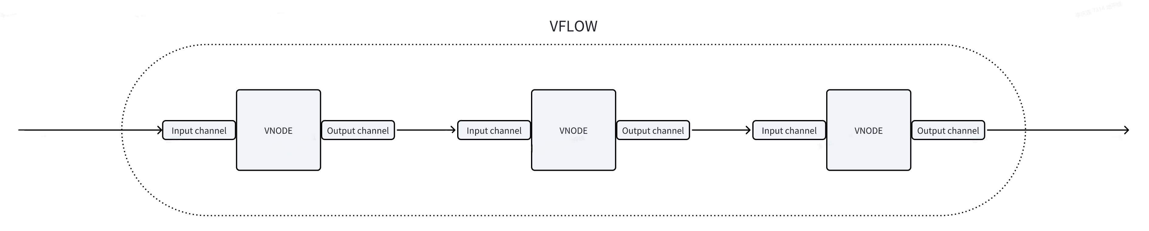
A vflow consists of one or more vnodes. Each vnode has one input channel and one or more output channels.
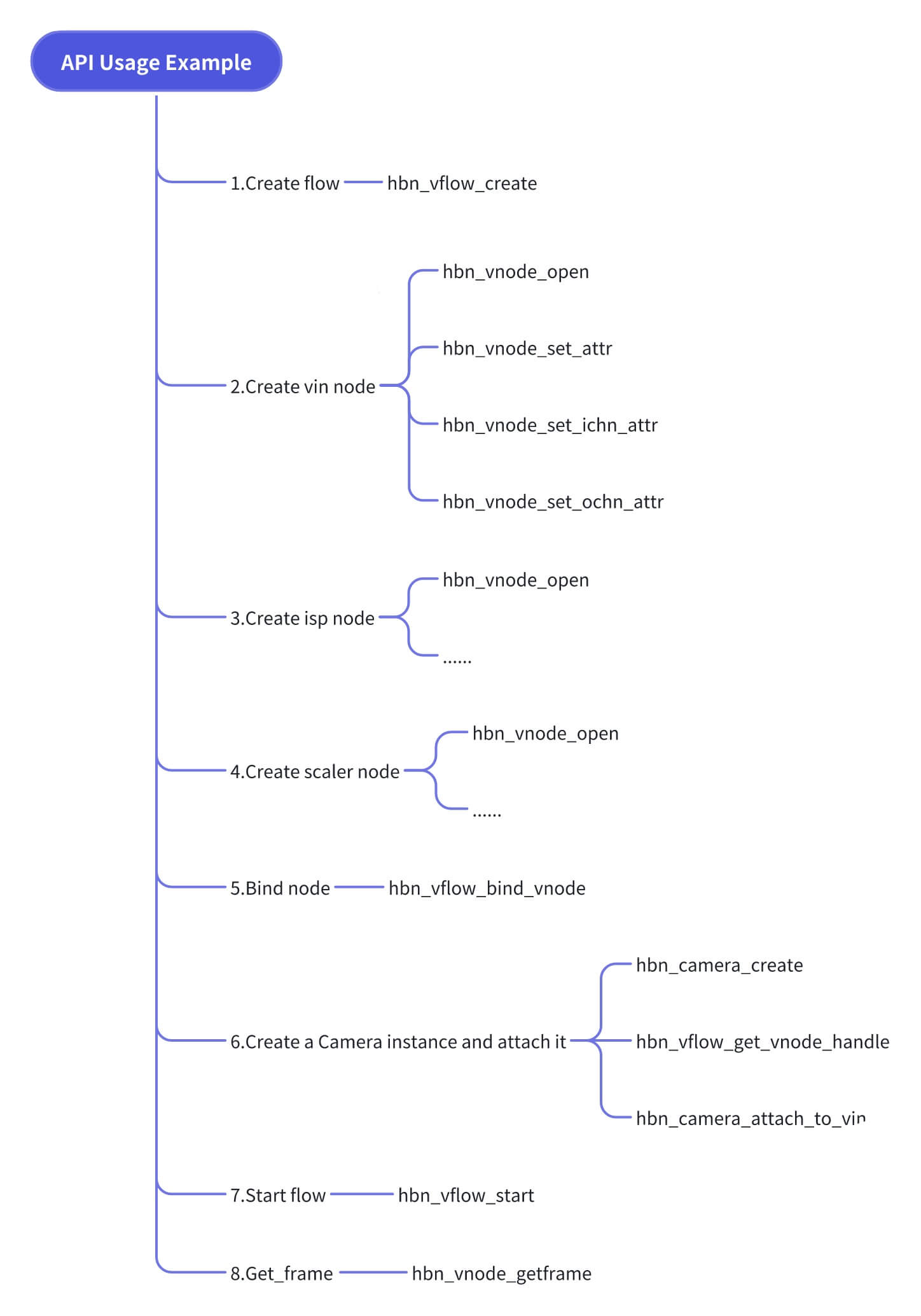
Example API usage:
API Reference
- hbn_vnode_open
【Function Declaration】
hobot_status hbn_vnode_open(hb_vnode_type vnode_type, uint32_t hw_id, int32_t ctx_id, hbn_vnode_handle_t *vnode_fd)
【Parameter Description】
[IN] hb_vnode_type vnode_type: Vnode type. Each hardware module corresponds to a specific vnode type, such as HB_VIN, HB_ISP, HB_PYM, etc.
[IN] uint32_t hw_id: Hardware ID of the module.
[IN] uint32_t ctx_id: Context ID of the module (a software concept). You can either specify a context ID or set it to AUTO_ALLOC_ID to let the SDK allocate one automatically.
[OUT] hbn_vnode_handle_t *vnode_fd: Returns the vnode handle of the module.
【Return Value】
Success: HBN_STATUS_SUCESS (0)
Failure: Negative error code; refer to the Return Value Description table.
【Function Description】
Initializes a specific module, opens its device node, and returns the module's vnode handle.
【Notes】
None.
- hbn_vnode_close
【Function Declaration】
void hbn_vnode_close(hbn_vnode_handle_t vnode_fd)
【Parameter Description】
[IN] hbn_vnode_handle_t vnode_fd: Vnode handle of the module.
【Return Value】
None
【Function Description】
Closes the module's device node.
【Notes】
If hbn_vflow_destroy has been called, there is no need to call hbn_vnode_close.
hbn_vnode_close should only be used when a module is used independently (e.g., GDC loopback). If the module is part of a vflow, calling hbn_vflow_destroy is sufficient—do not call hbn_vnode_close.
- hbn_vnode_set_attr
【Function Declaration】
hobot_status hbn_vnode_set_attr(hbn_vnode_handle_t vnode_fd, void *attr)
【Parameter Description】
[IN] hbn_vnode_handle_t vnode_fd: Vnode handle of the module.
[IN] void *attr: Pointer to the module's basic attribute structure. This structure can be vin_attr_t, isp_attr_t, pym_attr_t, etc.—i.e., any structure named <module_name>_attr_t.
【Return Value】
Success: HBN_STATUS_SUCESS (0)
Failure: Negative error code; refer to the Return Value Description table.
【Function Description】
Sets the basic attributes of a module.
【Notes】
None.
- hbn_vnode_get_attr
【Function Declaration】
hobot_status hbn_vnode_get_attr(hbn_vnode_handle_t vnode_fd, void *attr)
【Parameter Description】
[IN] hbn_vnode_handle_t vnode_fd: Vnode handle of the module.
[OUT] void *attr: Pointer to the module's basic attribute structure (e.g., vin_attr_t, isp_attr_t, pym_attr_t, etc.).*attr: Pointer to the basic attribute structure of the module. The basic attribute structure can be vin_attr_t, isp_attr_t, pym_attr_t, etc.—any attribute structure named with the module name followed by _attr_t.
【Return Value】
Success: HBN_STATUS_SUCCESS 0
Failure: Negative error code for exceptions; refer to the return value description.
【Function Description】
Obtains the basic attributes of a module.
【Notes】
None
- hbn_vnode_set_attr_ex
【Function Declaration】
hobot_status hbn_vnode_set_attr_ex(hbn_vnode_handle_t vnode_fd, void *attr)
【Parameter Description】
[IN] hbn_vnode_handle_t vnode_fd: vnode handle of the module;
[IN] void *attr: Pointer to the extended attribute structure of the module. The extended attribute structure can be vin_attr_ex_t, etc.—any attribute structure named with the module name followed by _attr_ex_t;
【Return Value】
Success: HBN_STATUS_SUCCESS 0
Failure: Negative error code for exceptions; refer to the return value description.
【Function Description】
Sets the extended attributes of a module, which can be dynamically configured during application runtime.
【Notes】
None
- hbn_vnode_get_attr_ex
【Function Declaration】
hobot_status hbn_vnode_get_attr_ex(hbn_vnode_handle_t vnode_fd, void *attr)
【Parameter Description】
[IN] hbn_vnode_handle_t vnode_fd: vnode handle of the module;
[OUT] void
*attr: Pointer to the extended attribute structure of the module. The extended attribute structure can be vin_attr_ex_t, etc.—any attribute structure named with the module name followed by _attr_ex_t;
【Return Value】
Success: HBN_STATUS_SUCCESS 0
Failure: Negative error code for exceptions; refer to the return value description.
【Function Description】
Obtains the extended attributes of a module.
【Notes】
None
- hbn_vnode_set_ochn_attr
【Function Declaration】
hobot_status hbn_vnode_set_ochn_attr(hbn_vnode_handle_t vnode_fd, uint32_t
ochn_id, void *attr)
【Parameter Description】
[IN] hbn_vnode_handle_t vnode_fd: vnode handle of the module;
[IN] uint32_t ochn_id: Output channel ID of the module; refer to the module channel description for valid channel IDs;
[IN] void *attr: Pointer to the output channel attribute structure of the module. The output channel attribute can be vin_ochn_attr_t, isp_ochn_attr_t, etc.—any attribute structure named with the module name followed by _ochn_attr_t;
【Return Value】
Success: HBN_STATUS_SUCCESS 0
Failure: Negative error code for exceptions; refer to the return value description.
【Function Description】
Sets the output channel attributes of a module.
【Notes】
None
- hbn_vnode_get_ochn_attr
【Function Declaration】
hobot_status hbn_vnode_get_ochn_attr(hbn_vnode_handle_t vnode_fd, uint32_t
ochn_id, void *attr)
【Parameter Description】
[IN] hbn_vnode_handle_t vnode_fd: vnode handle of the module;
[IN] uint32_t ochn_id: Output channel ID of the module; refer to the module channel description for valid channel IDs;
[OUT] void *attr: Pointer to the output channel attribute structure of the module. The output channel attribute can be vin_ochn_attr_t, isp_ochn_attr_t, etc.—any attribute structure named with the module name followed by _ochn_attr_t;
【Return Value】
Success: HBN_STATUS_SUCCESS 0
Failure: Negative error code for exceptions; refer to the return value description.
【Function Description】
Obtains the output channel attributes of a module.
【Notes】
None
- hbn_vnode_set_ochn_attr_ex
【Function Declaration】
hobot_status hbn_vnode_set_ochn_attr_ex(hbn_vnode_handle_t vnode_fd, uint32_t
ochn_id, void *attr)
【Parameter Description】
[IN] hbn_vnode_handle_t vnode_fd: vnode handle of the module;
[IN] uint32_t ochn_id: Output channel ID of the module; refer to the module channel description for valid channel IDs;
[IN] void *attr: Pointer to the extended output channel attribute structure of the module. The extended output channel attribute can be pym_ochn_attr_ex_t, etc.—any attribute structure named with the module name followed by _ochn_attr_ex_t;
【Return Value】
Success: HBN_STATUS_SUCCESS 0
Failure: Negative error code for exceptions; refer to the return value description.
【Function Description】
Sets the extended output channel attributes of a module, which can be dynamically configured during application runtime.
【Notes】
None
- hbn_vnode_set_ichn_attr
【Function Declaration】
hobot_status hbn_vnode_set_ichn_attr(hbn_vnode_handle_t vnode_fd, uint32_t
ichn_id, void *attr)
【Parameter Description】
[IN] hbn_vnode_handle_t vnode_fd: vnode handle of the module;
[IN] uint32_t ichn_id: Input channel ID of the module; refer to the module channel description for valid channel IDs;
[IN] void *attr: Pointer to the input channel attribute structure of the module. The input channel attribute can be vin_ichn_attr_t, isp_ichn_attr_t, etc.—any attribute structure named with the module name followed by _ichn_attr_t;
【Return Value】
Success: HBN_STATUS_SUCCESS 0
Failure: Negative error code for exceptions; refer to the return value description.
【Function Description】
Sets the input channel attributes of a module.
【Notes】
None
- hbn_vnode_get_ichn_attr
【Function Declaration】
hobot_status hbn_vnode_get_ichn_attr(hbn_vnode_handle_t vnode_fd, uint32_t
ichn_id, void *attr)
【Parameter Description】
[IN] hbn_vnode_handle_t vnode_fd: vnode handle of the module;[IN] uint32_t ichn_id: Input channel ID of the module; refer to the module channel description for channel IDs.
[OUT] void *attr: Pointer to the input channel attribute structure of the module. The input channel attributes can be vin_ichn_attr_t, isp_ichn_attr_t, etc.—any attribute ending with the module name followed by _ichn_attr_t.
【Return Value】
Success: HBN_STATUS_SUCCESS 0
Failure: Negative error code for exceptions; refer to the return value description.
【Function Description】
Obtain the input channel attributes of the module.
【Notes】
None
- hbn_vnode_set_ochn_buf_attr
【Function Declaration】
hobot_status hbn_vnode_set_ochn_buf_attr(hbn_vnode_handle_t vnode_fd, uint32_t
ochn_id, hbn_buf_alloc_attr_t *alloc_attr)
【Parameter Description】
[IN] hbn_vnode_handle_t vnode_fd: vnode handle of the module;
[IN] uint32_t ochn_id: Output channel ID of the module; refer to the module channel description for channel IDs;
[IN] hbn_buf_alloc_attr_t *alloc_attr: Buffer allocation attributes;
【Return Value】
Success: HBN_STATUS_SUCCESS 0
Failure: Negative error code for exceptions; refer to the return value description.
【Function Description】
Set the buffer attributes for the output channel.
【Notes】
None
- hbn_vnode_start
【Function Declaration】
hobot_status hbn_vnode_start(hbn_vnode_handle_t vnode_fd)
【Parameter Description】
[IN] hbn_vnode_handle_t vnode_fd: vnode handle of the module;
【Return Value】
Success: HBN_STATUS_SUCCESS 0
Failure: Negative error code for exceptions; refer to the return value description.
【Function Description】
Start the module.
【Notes】
The module must be opened before starting.
- hbn_vnode_stop
【Function Declaration】
hobot_status hbn_vnode_stop(hbn_vnode_handle_t vnode_fd)
【Parameter Description】
[IN] hbn_vnode_handle_t vnode_fd: vnode handle of the module;
【Return Value】
Success: HBN_STATUS_SUCCESS 0
Failure: Negative error code for exceptions; refer to the return value description.
【Function Description】
Stop the module.
【Notes】
None
- hbn_vnode_getframe
【Function Declaration】
hobot_status hbn_vnode_getframe(hbn_vnode_handle_t vnode_fd, uint32_t ochn_id,
uint32_t millisecondTimeout, hbn_vnode_image_t *out_img)
【Parameter Description】
[IN] hbn_vnode_handle_t vnode_fd: vnode handle of the module;
[IN] uint32_t ochn_id: Output channel ID of the module; refer to the module channel description for channel IDs;
[IN] uint32_t millisecondTimeout: Timeout waiting period (in milliseconds);
[OUT] hbn_vnode_image_t *out_img: Address of the output image buffer structure;
【Return Value】
Success: HBN_STATUS_SUCCESS 0
Failure: Negative error code for exceptions; refer to the return value description.
【Function Description】
Retrieve an image from the module's output channel; this is a blocking interface.
【Notes】
None
- hbn_vnode_releaseframe
【Function Declaration】
hobot_status hbn_vnode_releaseframe(hbn_vnode_handle_t vnode_fd, uint32_t
ochn_id, hbn_vnode_image_t *img)
【Parameter Description】
[IN] hbn_vnode_handle_t vnode_fd: vnode handle of the module;
[IN] uint32_t ochn_id: Output channel ID of the module; refer to the module channel description for channel IDs;
[IN] hbn_vnode_image_t *img: Address of the image buffer structure;
【Return Value】
Success: HBN_STATUS_SUCCESS 0
Failure: Negative error code for exceptions; refer to the return value description.
【Function Description】
Release the image buffer; the buffer will be returned to the specified output channel.
【Notes】
None
- hbn_vnode_getframe_group
【Function Declaration】
hobot_status hbn_vnode_getframe_group(hbn_vnode_handle_t vnode_fd, uint32_t
ochn_id, uint32_t millisecondTimeout, hbn_vnode_image_group_t *out_img);
【Parameter Description】
[IN] hbn_vnode_handle_t vnode_fd: vnode handle of the module;
[IN] uint32_t ochn_id: Output channel ID of the module; refer to the module channel description for channel IDs;
[IN] uint32_t millisecondTimeout: Timeout waiting period (in milliseconds);
[OUT] hbn_vnode_image_group_t *out_img: Address of the output image buffer structure;
【Return Value】
Success: HBN_STATUS_SUCCESS 0
Failure: Negative error code for exceptions; refer to the return value description.
【Function Description】
Retrieve a multi-layer aggregated image from the module's output channel; this is a blocking interface.
【Notes】
This interface must be used to obtain output images from ISP and PYM.
- hbn_vnode_releaseframe_group
【Function Declaration】
hobot_status hbn_vnode_releaseframe_group(hbn_vnode_handle_t vnode_fd, uint32_t
ochn_id, hbn_vnode_image_group_t *img)
【Parameter Description】
[IN] hbn_vnode_handle_t vnode_fd: vnode handle of the module;
[IN] uint32_t ochn_id: Output channel ID of the module; refer to the module channel description for channel IDs;
[IN] hbn_vnode_image_t *img: Address of the image buffer structure;
【Return Value】
Success: HBN_STATUS_SUCCESS 0
Failure: Negative error code for exceptions; refer to the return value description.
【Function Description】
Releases a multi-layer aggregated image buffer. The buffer will be returned to the specified output channel.
【Notes】
None
- hbn_vnode_sendframe
【Function Declaration】
hobot_status hbn_vnode_sendframe(hbn_vnode_handle_t vnode_fd, uint32_t ichn_id, hbn_vnode_image_t *img)
【Parameter Description】
[IN] hbn_vnode_handle_t vnode_fd: Vnode handle of the module;
[IN] uint32_t ichn_id: Input channel ID of the module; refer to the module channel description for channel IDs;
[IN] hbn_vnode_image_t *img: Address of the input image buffer;
【Return Value】
Success: HBN_STATUS_SUCCESS 0
Failure: Negative error code for exceptions; refer to the return value description.
【Function Description】
Sends an image to the input channel of the module, triggering the module to process it. This is a blocking API that waits until hardware processing completes before returning, with a default timeout of 1 second.
【Notes】
None
- hbn_vflow_create
【Function Declaration】
hobot_status hbn_vflow_create(hbn_vflow_handle_t *vflow_fd)
【Parameter Description】
[OUT] hbn_vflow_handle_t *vflow_fd: Vflow handle;
【Return Value】
Success: HBN_STATUS_SUCCESS 0
Failure: Negative error code for exceptions; refer to the return value description.
【Function Description】
Creates a vflow and returns the vflow handle.
【Notes】
None
- hbn_vflow_destroy
【Function Declaration】
void hbn_vflow_destroy(hbn_vflow_handle_t vflow_fd)
【Parameter Description】
[IN] hbn_vflow_handle_t *vflow_fd: Vflow handle;
【Return Value】
None
【Function Description】
Destroys a vflow based on the provided vflow handle.
【Notes】
None
- hbn_vflow_add_vnode
【Function Declaration】
hobot_status hbn_vflow_add_vnode(hbn_vflow_handle_t vflow_fd, hbn_vnode_handle_t vnode_fd)
【Parameter Description】
[IN] hbn_vflow_handle_t *vflow_fd: Vflow handle;
[IN] hbn_vnode_handle_t vnode_fd: Vnode handle of the module;
【Return Value】
Success: HBN_STATUS_SUCCESS 0
Failure: Negative error code for exceptions; refer to the return value description.
【Function Description】
Adds a module into the vflow for management by the vflow.
【Notes】
None
- hbn_vflow_bind_vnode
【Function Declaration】
hobot_status hbn_vflow_bind_vnode(hbn_vflow_handle_t vflow_fd, hbn_vnode_handle_t src_vnode_fd, uint32_t out_chn, hbn_vnode_handle_t dst_vnode_fd, uint32_t in_chn)
【Parameter Description】
[IN] hbn_vflow_handle_t *vflow_fd: Vflow handle;
[IN] hbn_vnode_handle_t src_vnode_fd: Vnode handle of the source module;
[IN] uint32_t out_chn: Output channel ID of the source module; refer to the module channel description for channel IDs;
[IN] hbn_vnode_handle_t dst_vnode_fd: Vnode handle of the destination module;
[IN] uint32_t in_chn: Input channel ID of the destination module; refer to the module channel description for channel IDs;
【Return Value】
Success: HBN_STATUS_SUCCESS 0
Failure: Negative error code for exceptions; refer to the return value description.
【Function Description】
Binds two modules together. After binding, data frames from the src_vnode_fd module will automatically flow to the dst_vnode_fd module.
【Notes】
The flow must be created, and the modules must be opened.
- hbn_vflow_unbind_vnode
【Function Declaration】
hobot_status hbn_vflow_unbind_vnode(hbn_vflow_handle_t vflow_fd, hbn_vnode_handle_t src_vnode_fd, uint32_t out_chn, hbn_vnode_handle_t dst_vnode_fd, uint32_t in_chn)
【Parameter Description】
[IN] hbn_vflow_handle_t *vflow_fd: Vflow handle;
[IN] hbn_vnode_handle_t src_vnode_fd: Vnode handle of the source module;
[IN] uint32_t out_chn: Output channel ID of the source module; refer to the module channel description for channel IDs;
[IN] hbn_vnode_handle_t dst_vnode_fd: Vnode handle of the destination module;
[IN] uint32_t in_chn: Input channel ID of the destination module; refer to the module channel description for channel IDs;
【Return Value】
Success: HBN_STATUS_SUCCESS 0
Failure: Negative error code for exceptions; refer to the return value description.
【Function Description】
Unbinds the src_vnode_fd and dst_vnode_fd modules.
【Notes】
Not supported currently.
- hbn_vflow_start
【Function Declaration】
hobot_status hbn_vflow_start(hbn_vflow_handle_t vflow_fd)
【Parameter Description】
[IN] hbn_vflow_handle_t vflow_fd: Vflow handle;
【Return Value】
Success: HBN_STATUS_SUCCESS 0
Failure: Exception indicated by a negative error code; refer to the return value description.
【Function Description】
Start a vflow. All vnodes contained within the vflow will be started.
【Notes】
The module vnode must be added to the vflow in advance.
- hbn_vflow_stop
【Function Declaration】
hobot_status hbn_vflow_stop(hbn_vflow_handle_t vflow_fd)
【Parameter Description】
[IN] hbn_vflow_handle_t vflow_fd: vflow handle;
【Return Value】
Success: HBN_STATUS_SUCCESS 0
Failure: Exception indicated by a negative error code; refer to the return value description.
【Function Description】
Stop a vflow. All vnodes contained within the vflow will be stopped.
【Notes】
This function should be used in pair with hbn_vflow_start.
- hbn_vflow_get_vnode_handle
【Function Declaration】
hbn_vnode_handle_t hbn_vflow_get_vnode_handle(hbn_vflow_handle_t vflow_fd,
hb_vnode_type vnode_type, uint32_t index)
【Parameter Description】
[IN] hbn_vflow_handle_t vflow_fd: vflow handle;
[IN] hb_vnode_type vnode_type: module ID;
[IN] uint32_t index: context ID, range [0, 7]
【Return Value】
Success: HBN_STATUS_SUCCESS 0
Failure: Exception indicated by a negative error code; refer to the return value description.
【Function Description】
Obtain the vnode handle via module ID and context ID.
【Notes】
The module must be opened in advance.
ISP API
- hbn_isp_get_ae_statistics
【Function Declaration】
int32_t hbn_isp_get_ae_statistics(hbn_vnode_handle_t vnode_fd, isp_statistics_t *ae_statistics, int32_t time_out)
【Parameter Description】
[IN] hbn_vflow_handle_t vflow_fd: vflow handle;
[IN] int32_t time_out: timeout duration for waiting;
[OUT] isp_statistics_t *ae_statistics: AE statistics;
【Return Value】
Success: HBN_STATUS_SUCCESS 0
Failure: Exception indicated by a negative error code; refer to the return value description.
【Function Description】
Obtain AE statistics (1024-bin histogram) via the vflow_fd of the ISP module. The data is fixed at 2096 bytes, arranged as shown in the figure below:
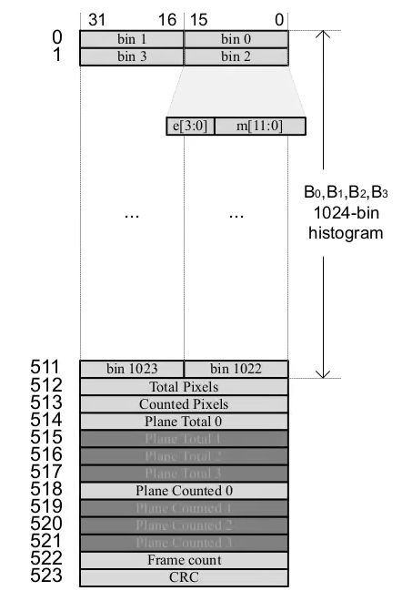
- hbn_isp_release_ae_statistics
【Function Declaration】
int32_t hbn_isp_release_ae_statistics(hbn_vnode_handle_t vnode_fd, isp_statistics_t *ae_statistics)
【Parameter Description】
[IN] hbn_vflow_handle_t vflow_fd: vflow handle;
[IN] isp_statistics_t *ae_statistics: AE statistics;
【Return Value】
Success: HBN_STATUS_SUCCESS 0
Failure: Exception indicated by a negative error code; refer to the return value description.
【Function Description】
Release the obtained AE statistics. This function must be used in pair with hbn_isp_get_ae_statistics.
Parameter Description
Common
hbn_vnode_image_t
| Name | Type | Description | Max Value | Min Value | Default | Required |
|---|---|---|---|---|---|---|
| info | hbn_frame_info_t | Image info structure | – | – | – | – |
| buffer | hb_mem_graphic_buf_t | Image memory info | – | – | – | – |
| metadata | void * | Metadata | – | – | – | – |
hbn_frame_info_t
| Name | Type | Description | Max Value | Min Value | Default | Required |
|---|---|---|---|---|---|---|
| frame_id | uint32_t | Frame ID | – | – | – | – |
| timestamps | uint64_t | System timestamp | – | – | – | – |
| tv | struct timeval | Hardware timestamp | – | – | – | – |
| trig_tv | struct timeval | External-triggered hardware timestamp | – | – | – | – |
| bufferindex | int32_t | Buffer index | – | – | – | – |
hb_mem_graphic_buf_t
| Name | Type | Description | Max Value | Min Value | Default | Required |
|---|---|---|---|---|---|---|
| fd[MAX_GRAPHIC_BUF_COMP] | int32_t | File descriptor | – | – | – | – |
| plane_cnt | int32_t | Number of planes | – | – | – | – |
| format | int32_t | Image format | – | – | – | – |
| width | int32_t | Width | – | – | – | – |
| height | int32_t | Height | – | – | – | – |
| stride | int32_t | Width stride | – | – | – | – |
| vstride | int32_t | Height stride | – | – | – | – |
| is_contig | int32_t | Whether buffer physical address is contiguous | – | – | – | – |
| share_id[MAX_GRAPHIC_BUF_COMP] | int32_t | Share ID | – | – | – | – |
| flags | int64_t | Flags | – | – | – | – |
| size[MAX_GRAPHIC_BUF_COMP] | uint64_t | Buffer size | – | – | – | – |
| virt_addr[MAX_GRAPHIC_BUF_COMP] | uint8_t * | Virtual address | – | – | – | – |
| phys_addr[MAX_GRAPHIC_BUF_COMP] | uint64_t | Physical address | – | – | – | – |
| offset[MAX_GRAPHIC_BUF_COMP] | uint64_t | Memory offset | – | – | – | – |
hbn_vnode_image_group_t
| Name | Type | Description | Max Value | Min Value | Default | Required |
|---|---|---|---|---|---|---|
| info | hbn_frame_info_t | Image info structure | – | – | – | – |
| buf_group | hb_mem_graphic_buf_group_t | Group image memory info | – | – | – | – |
| metadata | void * | Metadata | – | – | – | – |
hb_mem_graphic_buf_group_t
| Name | Type | Description | Max Value | Min Value | Default | Required |
|---|---|---|---|---|---|---|
| graph_group[HB_MEM_MAXIMUM_GRAPH_BUF]; | hb_mem_graphic_buf_t | Image memory info | – | – | – | – |
| group_id | int32_t | Group ID | – | – | – | – |
| bit_map | uint32_t | Bitmask indicating available layers in graph_group | – | – | – | – |
VIN
vin_attr_t
| Name | Type | Description | Max Value | Min Value | Default | Required |
|---|---|---|---|---|---|---|
| vin_node_attr | vin_node_attr_t | VIN node attribute structure | – | – | – | Yes |
| magicNumber | uint32_t | Magic number for attribute structure validation; must be set to MAGIC_NUM | – | – | – | Yes |
vin_node_attr_t
| Name | Type | Description | Max Value | Min Value | Default | Required |
|---|---|---|---|---|---|---|
| cim_attr | cim_attr_t | CIM parameters | – | – | – | Yes |
| lpwm_attr | lpwm_attr_t | LPWM parameters | – | – | – | No |
| vcon_attr | vcon_attr_t | VCON parameters | – | – | – | No |
| magicNumber | uint32_t | Magic number for attribute structure validation; must be set to MAGIC_NUM | – | – | – | Yes |
cim_attr_t
| Name | Type | Description | Max Value | Min Value | Default | Required |
|---|---|---|---|---|---|---|
| mipi_en | uint32_t | Enable MIPI input | 1 | 0 | – | Yes |
| mipi_rx | uint32_t | MIPI RX index; options: 0, 1, 4 | 4 | 0 | – | Yes |
| vc_index | uint32_t | CIM IPI index | 3 | 0 | – | Yes |
| cim_pym_flyby | uint32_t | Enable CIM PYM hardware bypass | 1 | 0 | – | Yes |
| cim_isp_flyby | uint32_t | Enable CIM ISP hardware bypass | 1 | 0 | – | Yes |
| Name | Type | Description | Max | Min | Default | Required |
|---|---|---|---|---|---|---|
| format | uint32_t | MIPI input image format, e.g., raw12 corresponds to 0x2c | 0x27 | 0x1E | - | Yes |
| width | uint32_t | MIPI input image width | 4096 | 32 | - | Yes |
| height | uint32_t | MIPI input image height | 2160 | 32 | - | Yes |
vin_ochn_attr_t
| Name | Type | Description | Max | Min | Default | Required |
|---|---|---|---|---|---|---|
| ddr_en | uint32_t | Enable CIM DDR output | 1 | 0 | - | No |
| roi_en | uint32_t | Enable CIM ROI channel output | 1 | 0 | - | No |
| emb_en | uint32_t | Enable CIM EMB channel output | 1 | 0 | - | No |
| rawds_en | uint32_t | Enable RAW scaler | 1 | 0 | - | No |
| pingpong_ring | uint32_t | Enable ping-pong buffer | 1 | 0 | - | No |
| ochn_attr_type | vin_ochn_attr_type_e | Output channel type: VIN_MAIN_FRAME (main data path), VIN_ONLINE (online output path), VIN_EMB (embedded data path), VIN_ROI (ROI data path) | - | - | - | Yes |
| vin_basic_attr | vin_basic_attr_t | Basic VIN attributes | - | - | - | Yes |
| rawds_attr | vin_rawds_attr_t | VIN RAW scaler attributes | - | - | - | No |
| roi_attr | struct vin_roi_attr_s | VIN ROI attributes | - | - | - | No |
| emb_attr | vin_emb_attr_t | VIN embedded attributes | - | - | - | No |
| magicNumber | uint32_t | Attribute structure checksum; must be set to the fixed value MAGIC_NUM | - | - | - | Yes |
vin_basic_attr_t
| Name | Type | Description | Max | Min | Default | Required |
|---|---|---|---|---|---|---|
| pack_mode | uint32_t | Enable packing; packing enabled by default if not configured | 1 | 0 | 1 | No |
| wstride | uint32_t | Output width stride; if set to 0, calculated internally | 1 | 0 | 1 | No |
| vstride | uint32_t | Output height stride; if set to 0, calculated internally | 1 | 0 | 1 | No |
| format | uint32_t | Output image format, e.g., raw12 corresponds to 0x2c | 0x27 | 0x1E | - | Yes |
ISP
isp_attr_t
| Name | Type | Description | Max | Min | Default | Required |
|---|---|---|---|---|---|---|
| channel | isp_channel_t | ISP channel attributes | - | - | - | Yes |
| sched_mode | sched_mode_e | ISP scheduling mode: 1 = SCHED_MODE_MANUAL (manual mode), 2 = SCHED_MODE_PASS_THRU (fully online mode) | 2 | 1 | - | Yes |
| work_mode | isp_work_mode_e | ISP working mode: 0 = ISP_WORK_MODE_NORMAL (normal mode), 1 = ISP_WORK_MODE_TPG (ISP outputs test pattern), 2 = ISP_WORK_MODE_CIM_TPG (CIM outputs test pattern) | 2 | 0 | - | No |
| hdr_mode | hdr_mode_e | Enable ISP HDR mode | 1 | 0 | - | No |
| size | image_size_t | ISP processing resolution | - | - | - | No |
| frame_rate | uint32_t | ISP frame rate | 120 | 1 | - | No |
| isp_combine | isp_combine_t | ISP master-slave mode | - | - | - | No |
| algo_state | uint32_t | Enable 2A algorithms | 1 | 0 | - | No |
isp_channel_t
| Name | Type | Description | Max | Min | Default | Required |
|---|---|---|---|---|---|---|
| hw_id | uint32_t | ISP hardware ID | 1 | 0 | - | Yes |
| slot_id | uint32_t | ISP internal hardware channel: configure 0 | 11 | 0 | 0 | Yes |
image_size_t
| Name | Type | Description | Max | Min | Default | Required |
|---|---|---|---|---|---|---|
| width | uint32_t | ISP processing width | 4096 | 32 | - | Yes |
| height | uint32_t | ISP processing height | 2160 | 32 | - | Yes |
isp_ichn_attr_t
| Name | Type | Description | Max | Min | Default | Required |
|---|---|---|---|---|---|---|
| input_crop_cfg | crop_cfg_t | Input crop configuration | - | - | - | No |
| in_buf_noclean | uint32_t | Whether to perform cache clean on input buffer | 1 | 0 | - | No |
| in_buf_noncached | uint32_t | Whether to allocate input buffer as non-cacheable memory | 1 | 0 | - | No |
crop_cfg_t
| Name | Type | Description | Max | Min | Default | Required |
|---|---|---|---|---|---|---|
| rect | image_rect_t | Input crop rectangle | - | - | - | No |
| enable | HB_BOOL | Enable crop | 1 | 0 | - | No |
image_rect_t
| Name | Type | Description | Max | Min | Default | Required |
|---|---|---|---|---|---|---|
| x | uint32_t | X coordinate | - | - | - | No |
| y | uint32_t | Y coordinate | - | - | - | No |
| width | uint32_t | Rect width | - | - | - | No |
| height | uint32_t | Rect height | - | - | - | No |
isp_ochn_attr_t
| Name | Type | Description | Max | Min | Default | Required |
|---|---|---|---|---|---|---|
| stream_output_mode | isp_stream_output_mode_e | Whether to enable OTF output: 1 = enable, 0 = disable | 1 | 0 | 0 | Yes |
| axi_output_mode | isp_axi_output_mode_e | DDR output type: AXI_OUTPUT_MODE_DISABLE = 0, | 14 | 0 | 0 | Yes |
| AXI_OUTPUT_MODE_RGB888 = 1, | ||||||
| AXI_OUTPUT_MODE_RAW8 = 2, | ||||||
| AXI_OUTPUT_MODE_RAW10 = 3, | ||||||
| AXI_OUTPUT_MODE_RAW12 = 4, | ||||||
| AXI_OUTPUT_MODE_RAW16 = 5, | ||||||
| AXI_OUTPUT_MODE_RAW24 = 6, | ||||||
| AXI_OUTPUT_MODE_YUV444 = 7, | ||||||
| AXI_OUTPUT_MODE_YUV422 = 8, /* yuv422 */ | ||||||
| AXI_OUTPUT_MODE_YUV420 = 9, /* yuv420 */ | ||||||
| AXI_OUTPUT_MODE_IR8 = 10, | ||||||
| AXI_OUTPUT_MODE_YUV420_RAW12 = 11, /* yuv420 & raw12 */ | ||||||
| AXI_OUTPUT_MODE_YUV422_RAW12 = 12, /* yuv422 & raw12 */ | ||||||
| AXI_OUTPUT_MODE_YUV420_RAW16 = 13, /* yuv420 & raw16 */ | ||||||
| AXI_OUTPUT_MODE_YUV422_RAW16 = 14, /* yuv422 & raw16 */ | ||||||
| output_crop_cfg | crop_cfg_t | Output crop configuration | - | - | - | Yes |
| out_buf_noinvalid | uint32_t | Whether to perform cache invalidate on output buffer | 1 | 0 | 0 | No |
| out_buf_noncached | uint32_t | Whether to allocate output buffer as non-cacheable memory | 1 | 0 | 0 | No |
| buf_num | uint32_t | Number of output buffers to allocate | 16 | 3 | 0 | Yes |
YNR
ynr_init_attr
| Name | Type | Description | Max | Min | Default | Required |
|---|---|---|---|---|---|---|
| work_mode | uint32_t | YNR working mode | 2 | 1 | - | Yes |
| 1: Manual mode, online link, previous module is SW trigger; | ||||||
| 2: Single-channel online mode (previous PYM hardware directly connected); | ||||||
| slot_id | uint32_t | YNR hardware channel ID | 7 | 0 | - | Yes |
| width | uint32_t | YNR processing width | 2048 | 32 | Yes | |
| height | uint32_t | YNR processing height | 2048 | 32 | Yes | |
| nr_static_switch | uint32_t | nr3den <<1 | nr2d_en | ||||
| in_stride | uint32_t | Y stride and UV stride | Yes | |||
| nr2d_en | uint32_t | Enable 2D NR | 1 | 0 | Yes | |
| nr3d_en | uint32_t | Enable 3D NR | 1 | 0 | Yes | |
| dma_output_en | uint32_t | Enable DMA output | 1 | 0 | Yes | |
| If 3D NR is enabled, DMA output must be enabled | ||||||
| debug_en | uint32_t | Enable debug mode | 1 | 0 | No |
hobot_ynr_channel_input_config
| Name | Type | Description | Max | Min | Default | Required |
|---|---|---|---|---|---|---|
| ch_img_width | uint32_t | YNR input width | 4096 | 32 | - | Yes |
| ch_img_height | uint32_t | YNR input height | 2160 | 32 | - | Yes |
hobot_ynr_channel_output_config
| Name | Type | Description | Max | Min | Default | Required |
|---|---|---|---|---|---|---|
| ch_nr3d_pix_out_dma_byps | uint32_t | DMA output count; recommended to set to 0 | 4096 | 32 | - | Yes |
| ch_nr3d_debug_en | uint32_t | Debug switch; recommended to set to 0 | 1 | 0 | - | Yes |
PYM
roi_box_t
| Name | Type | Description | Max | Min | Default | Required |
|---|---|---|---|---|---|---|
| start_top | uint32_t | Y-axis position to crop from original image | DS layer: <= region_height BL layer:<= bl_base_height bl_base_height = region_width >> (ds_roi_layer + 1) | DS layer: >= region_height - out_height BL layer: >= bl_base_height - out_height | - | Yes |
| start_left | uint32_t | X-axis position to crop from original image | DS layer: <= region_width BL layer: <= bl_base_width bl_base_width = region_width >> (ds_roi_layer + 1) | DS layer: >= region_width - out_width BL layer: >= bl_base_width - out_width | - | Yes |
| region_width | uint32_t | Width of cropped region | - | - | - | Yes |
| region_height | uint32_t | Height of cropped region | - | - | - | Yes |
| wstride_uv | uint32_t | Output UV plane stride | - | Yes | ||
| wstride_y | uint32_t | Output Y plane stride | - | - | - | Yes |
| vstride | uint32_t | Height stride (hidden parameter; not recommended to configure) | - | - | out_height | Yes |
| step_v | uint32_t | - | - | (1 << 16) * (out_height - region_height) / out_height | No | |
| step_h | uint32_t | - | - | (1 << 16) * (out_width - region_width) / out_width | No | |
| out_width | uint32_t | Output image width | - | - | - | Yes |
| out_height | uint32_t | Output image height | - | - | - | Yes |
| phase_y_v | uint32_t | 0 | No | |||
| phase_y_h | uint32_t | 0 | No |
chn_ctrl_t
| Name | Type | Description | Max | Min | Default | Required |
|---|---|---|---|---|---|---|
| pixel_num_before_sol | uint32_t | - | - | 2 | Yes | |
| invalid_head_lines | uint32_t | - | - | - | No | |
| src_in_width | uint32_t | Input width, aligned to 2 | < 4096 | > 32 | - | Yes |
| src_in_height | uint32_t | Input height, aligned to 2 | < 4096 | > 32 | - | Yes |
| src_in_stride_y | uint32_t | Input Y plane stride, aligned to 16 | < 4096 | > src_in_width | - | Yes |
| src_in_stride_uv | uint32_t | Input UV stride, aligned to 16 | < 4096 | > src_in_width | - | Yes |
| suffix_hb_val | uint32_t | <= 152 | >= 16 | 100 | Yes | |
| prefix_hb_val | uint32_t | <= 2 | >= 0 | 2 | Yes | |
| suffix_vb_val | uint32_t | <= 20 | >= 0 | 10 | Yes | |
| prefix_vb_val | uint32_t | <= 2 | >= 0 | 0 | Yes | |
| bl_max_layer_en | uint8_t | When selecting BL layer, enable number of BL layers | > ds_roi_layer[chn] | 5 | Yes | |
| ds_roi_en | uint8_t | Enable DS layer output (total 6 layers, enabled per bit) | < (1 << 6) | - | - | Yes |
| ds_roi_uv_bypass | uint8_t | Enable DS layer UV plane output bypass (enabled per bit) | < (1 << 6) | - | - | No |
| ds_roi_sel[MAX_DS_NUM] | uint8_t | Layer selection: 0 = SRC layer; 1 = BL layer | < 3 | - | - | Yes |
| ds_roi_layer[MAX_DS_NUM] | uint8_t | When ds_roi_sel = 0, must be 0 | - | - | Yes | |
| ds_roi_info[MAX_DS_NUM] | roi_box_t | DS layer configuration | - | - | - | Yes |
pym_cfg_t
| Name | Type | Description | Max | Min | Default | Required |
|---|---|---|---|---|---|---|
| hw_id | uint8_t | pym hardware module ID (0, 1, 4) | - | - | - | Yes |
| pym_mode | uint8_t | pym operation mode: 1: Manual mode, online link, with preceding module as SW trigger; 2: Single-channel Online mode (direct hardware connection between preceding module and PYM); 3: Offline mode (input: YUV420SP, output: YUV420SP) | <= 3 | >= 1 | - | Yes |
| slot_id | uint8_t | pym hardware channel ID | 7 | 0 | - | No |
| out_buf_noinvalid | uint8_t | Whether the module's output buffer internally performs an "invalidate cache" operation | 1 | 0 | 1 | Yes |
| out_buf_noncached | uint8_t | Whether non-cacheable memory allocation is enabled for the module's output buffer | 1 | 0 | - | No |
| in_buf_noclean | uint8_t | Whether cache clean is performed on the input buffer | 1 | 0 | 1 | Yes |
| in_buf_noncached | uint8_t | Whether non-cacheable memory allocation is enabled for the module's input buffer (typically feedback buffer) | 1 | 0 | - | No |
| buf_consecutive | uint8_t | Whether memory is contiguous | 1 | 0 | - | No |
| pingpong_ring | uint8_t | Whether ping-pong buffer is enabled | - | No | ||
| output_buf_num | uint32_t | Number of output buffers; when PYM is in offline mode, the number of feedback buffers is allocated by default according to this value | <= 64 | 0 | - | Yes |
| timeout | uint32_t | Timeout duration | <= 10000 | - | No | |
| threshold_time | uint32_t | - | No | |||
| layer_num_trans_next | int32_t | Number of layers transferred to the subsequent module | < 6 | - | -1 | Yes |
| layer_num_share_prev | int32_t | < 6 | - | -1 | Yes | |
| chn_ctrl | chn_ctrl_t | Configure input/output format and size | ||||
| fb_buf_num | uint32_t | Number of feedback buffers | <= 16 | - | 2 | Yes |
| reserved[6] | uint32_t | Reserved field | - | - | - | No |
| magicNumber | uint32_t | Attribute structure verification value; must be set to the fixed value MAGIC_NUM | - | - | - | Yes |
GDC
gdc_cfg_t
| Name | Type | Description | Max | Min | Default | Required |
|---|---|---|---|---|---|---|
| input_width | uint32_t | Input image width, aligned to 2 | <= 3840 | >= 96 | - | Yes |
| input_height | uint32_t | Input image height, aligned to 2 | <= 2160 | >= 96 | - | Yes |
| output_width | uint32_t | Output image width | <= 3840 | >= 96 | - | Yes |
| output_height | uint32_t | Output image height | <= 2160 | >= 96 | - | Yes |
| buf_num | uint32_t | Number of normal input buffers | <= 32 | 0 | 6 | Yes |
| fb_buf_num | uint32_t | Number of feedback buffers | <= 32 | 0 | 2 | Yes |
| in_buf_noclean | uint32_t | Whether cache clean is performed on the input buffer | 1 | 0 | 1 | No |
| in_buf_noncached | uint32_t | Whether non-cacheable memory allocation is enabled for the module's input buffer (typically feedback buffer) | - | - | - | No |
| out_buf_noinvalid | uint32_t | Whether the module's output buffer internally performs an "invalidate cache" operation | - | - | 1 | No |
| out_buf_noncached | uint32_t | Whether non-cacheable memory allocation is enabled for the module's output buffer | - | - | - | No |
| gdc_pipeline | uint32_t | - | - | - | No |
STITCH
stitch_base_attr
| Name | Type | Description | Max | Min | Default | Required |
|---|---|---|---|---|---|---|
| mode | uint32_t | Operation mode | No | |||
| 0 - External buffer feedback mode | ||||||
| 1 - Internal buffer feedback mode | ||||||
| 2 - Flow binding mode | ||||||
| roi_nums | uint32_t | Number of ROI regions | 12 | 1 | Yes | |
| img_nums | uint32_t | Number of input images | - | 1 | Yes | |
| alpha_lut | struct | Alpha lookup table | No | |||
| lut_attr | ||||||
| beta_lut | struct | Beta lookup table | No | |||
| lut_attr | ||||||
| blending | struct | Blending attributes | Yes | |||
| blending_attr |
lut_attr
| Name | Type | Description | Max | Min | Default | Required |
|---|---|---|---|---|---|---|
| share_id | int32_t | Share ID of hbmem buffer | ||||
| Required for storing LUT buffer | ||||||
| Must be allocated via hbmem | ||||||
| vaddr | uint64_t | LUT virtual address | No | |||
| offset | uint64_t | Offset | No | |||
| size | uint64_t | Size | No |
blending_attr
| Name | Type | Description | Max | Min | Default | Required |
|---|---|---|---|---|---|---|
| roi_index | uint32_t | ROI index | Yes | |||
| blending_mode | uint32_t | Blending mode: | Yes | |||
| BLENDING_MODE_ONLINE = 0, // online mode | ||||||
| BLENDING_MODE_ALPHA = 1, // alpha mode | ||||||
| BLENDING_MODE_ALPH = 2, // alpha beta mode | ||||||
| BLENDING_MODE_SRC = 3, // src copy mode | ||||||
| BLENDING_MODE_ALPHA_SRC = 5 // alpha src0 mode | ||||||
| direct | uint32_t | Blending direction: | Yes | |||
| BLENDING_DIRECT_LT = 0, // left and top direction | ||||||
| BLENDING_DIRECT_RB = 1, // right and bottom direction | ||||||
| BLENDING_DIRECT_LB = 2, // left and bottom direction | ||||||
| BLENDING_DIRECT_RT = 3, // right and top direction | ||||||
| uv_en | uint32_t | Whether input image contains UV | Yes | |||
| src0_index | uint32_t | Source index corresponding to src0 | Yes | |||
| src1_index | uint32_t | Source index corresponding to src1 | Yes | |||
| margin | uint32_t | Optional parameter; may be omitted | No | |||
| margin_inv | uint32_t | Optional parameter; may be omitted | No | |||
| gain_src0_yuv | uint32_t | Fixed to 256 // 0: Y, 1: U, 2: V | Yes | |||
| gain_src1_yuv | uint32_t | Fixed to 256 // 0: Y, 1: U, 2: V | Yes |
roi_info
| Name | Type | Description | Max | Min | Default | Required |
|---|---|---|---|---|---|---|
| roi_index | uint32_t | ROI index | Yes | |||
| roi_x | uint32_t | Starting X coordinate | Yes | |||
| roi_y | uint32_t | Starting Y coordinate | Yes | |||
| roi_w | uint32_t | Width | Yes | |||
| roi_h | uint32_t | Height | Yes |
stitch_ch_attr
| Name | Type | Description | Max | Min | Default | Required |
|---|---|---|---|---|---|---|
| width | uint32_t | Input or output width | Yes | |||
| height | uint32_t | Input or output height | Yes | |||
| strid[MAX_STH_FRAME_PLAN] | uint32_t | Stride | Yes | |||
| rois[MAX_STH_ROI_NUMS] | struct roi_info | ROI region description | Yes |
Channel Binding Description
| Module | Output Channel ID | Channel Function |
|---|---|---|
| VIN | 0 | Offline channel, outputs camera frames to DDR |
| 1 | Online channel, connects to ISP or PYM | |
| ISP | 0 | Offline channel, outputs ISP-processed frames to DDR |
| 1 | Online channel, connects to PYM or YNR | |
| YNR | 1 | Online channel, connects to PYM |
| PYM | 0 | Offline channel, outputs PYM images to DDR |
| GDC | 0 | Offline channel, outputs GDC-processed frames to DDR |
"Online" indicates direct hardware connection; "Offline" indicates output to DDR buffer.
SLOT_ID and Debug Mode Description
- The ISP's
slot_idparameter selects the ISP hardware context. In CIM-direct-to-ISP scenarios,slot_idcan be 0–3; in CIM-DDR-ISP scenarios,slot_idcan be 4–11. Different channels must use distinctslot_idvalues. In ISP-online-YNR-online-PYM or ISP-online-PYM scenarios, theslot_idof YNR and PYM must match that of the ISP. - The PYM's
sched_modeparameter selects the ISP scheduling mode. In CIM-ISP direct hardware connection scenarios, select mode 2 (passthrough); in other scenarios, select mode 1 (manual). In ISP-online-YNR-online-PYM or ISP-online-PYM scenarios, the YNRwork_modeand PYMpym_modemust be consistent with the ISPsched_mode.
Return Value Description
| Error Code | Macro Definition | Description |
|---|---|---|
| 0 | HBN_STATUS_SUCESS | Success |
| 1 | HBN_STATUS_INVALID_NODE | Invalid vnode; corresponding vnode not found |
| 2 | HBN_STATUS_INVALID_NODETYPE | Invalid vnode type; corresponding vnode not found |
| 3 | HBN_STATUS_INVALID_HWID | Invalid hardware module ID |
| 4 | HBN_STATUS_INVALID_CTXID | Invalid context ID |
| 5 | HBN_STATUS_INVALID_OCHNID | Invalid output channel ID |
| 6 | HBN_STATUS_INVALID_ICHNID | Invalid input channel ID |
| 7 | HBN_STATUS_INVALID_FORMAT | Invalid format |
| 8 | HBN_STATUS_INVALID_NULL_PTR | Null pointer |
| 9 | HBN_STATUS_INVALID_PARAMETER | Invalid parameter; version check failed |
| 10 | HBN_STATUS_ILLEGAL_ATTR | Invalid parameter |
| 11 | HBN_STATUS_INVALID_FLOW | Invalid flow; corresponding flow not found |
| 12 | HBN_STATUS_FLOW_EXIST | Flow already exists |
| 13 | HBN_STATUS_FLOW_UNEXIST | Flow does not exist |
| 14 | HBN_STATUS_NODE_EXIST | Node already exists |
| 15 | HBN_STATUS_NODE_UNEXIST | Node does not exist |
| 16 | HBN_STATUS_NOT_CONFIG | Reserved |
| 17 | HBN_STATUS_CHN_NOT_ENABLED | Channel not enabled |
| 18 | HBN_STATUS_CHN_ALREADY_ENABLED | Channel already enabled |
| 19 | HBN_STATUS_ALREADY_BINDED | Node already bound |
| 20 | HBN_STATUS_NOT_BINDED | Node not bound |
| 21 | HBN_STATUS_TIMEOUT | Timeout |
| 22 | HBN_STATUS_NOT_INITIALIZED | Not initialized |
| 23 | HBN_STATUS_NOT_SUPPORT | Channel not supported or not activated |
| 24 | HBN_STATUS_NOT_PERM | Operation not permitted |
| 25 | HBN_STATUS_NOMEM | Insufficient memory |
| 26 | HBN_STATUS_INVALID_VNODE_FD | Invalid node file descriptor |
| 27 | HBN_STATUS_INVALID_ICHNID_FD | Invalid input channel file descriptor |
| 28 | HBN_STATUS_INVALID_OCHNID_FD | Invalid output channel file descriptor |
| 29 | HBN_STATUS_OPEN_OCHN_FAIL | Failed to open output channel |
| 30 | HBN_STATUS_OPEN_ICHN_FAIL | Failed to open input channel |
| 31 | HBN_STATUS_JSON_PARSE_FAIL | JSON parsing failed |
| 32 | HBN_STATUS_REQ_BUF_FAIL | Buffer request failed |
| 33 | HBN_STATUS_QUERY_BUF_FAIL | Buffer query failed |
| 34 | HBN_STATUS_SET_CONTROL_FAIL | Failed to set module control or tuning parameters (e.g., ISP effect parameters) |
| 35 | HBN_STATUS_GET_CONTROL_FAIL | Failed to get module control or tuning parameters (e.g., ISP effect parameters) |
| 36 | HBN_STATUS_NODE_START_FAIL | Node start failed |
| 37 | HBN_STATUS_NODE_STOP_FAIL | Node stop failed |
| 38 | HBN_STATUS_NODE_POLL_ERROR | Node channel poll error |
| 39 | HBN_STATUS_NODE_POLL_TIMEOUT | Node channel poll timeout |
| 40 | HBN_STATUS_NODE_POLL_FRAME_DROP | Frame drop occurred during node channel poll |
| 41 | HBN_STATUS_NODE_POLL_HUP | Node channel poll descriptor hang-up |
| 42 | HBN_STATUS_NODE_ILLEGAL_EVENT | Illegal event during node channel poll |
| 43 | HBN_STATUS_NODE_DEQUE_ERROR | Node channel dequeue buffer error |
| 44 | HBN_STATUS_ILLEGAL_BUF_INDEX | Invalid buffer index |
| 45 | HBN_STATUS_NODE_QUE_ERROR | Node channel queue buffer error |
| 46 | HBN_STATUS_FLUSH_FRAME_ERROR | Node channel frame flush error |
| 47 | HBN_STATUS_INIT_BIND_ERROR | Error occurred during JSON parsing and binding |
| 48 | HBN_STATUS_ADD_NODE_FAIL | Failed to add node to flow |
| 49 | HBN_STATUS_WRONG_CONFIG_ID | Unsupported node ID by the system |
| 50 | HBN_STATUS_BIND_NODE_FAIL | Error occurred during flow binding to node |
| 51 | HBN_STATUS_INVALID_VERSION | Version mismatch between lower-level driver module and upper-layer library |
| 52 | HBN_STATUS_GET_VERSION_ERROR | Error retrieving lower-level driver module version |
| 53 | HBN_STATUS_MEM_INIT_FAIL | hbmem memory initialization failed |
| 54 | HBN_STATUS_MEM_IMPORT_FAIL | hbmem memory import failed |
| 55 | HBN_STATUS_MEM_FREE_FAIL | hbmem memory release failed |
| 56 | HBN_STATUS_SYSFS_OPEN_FAIL | System file open failed |
| 57 | HBN_STATUS_STRUCT_SIZE_NOT_MATCH | HAL-layer structure size mismatch with kernel layer |
| 58 | HBN_STATUS_RGN_UNEXIST | Corresponding RGN data not found |
| 59 | HBN_STATUS_RGN_INVALID_OPERATION | Invalid RGN operation |
| 60 | HBN_STATUS_RGN_OPEN_FILE_FAIL | RGN module file open failed |
| 128 | HBN_STATUS_ERR_UNKNOW | Unknown error |
V4L2
Some modules of the S100 Camsys have already been integrated with V4L2, allowing acquisition of Camsys data streams through standard V4L2 programming and open-source tools.
Usage
After system boot-up, camsys runs in hbn mode by default. You can switch to V4L2 mode by loading the camsys V4L2 kernel module (ko).
Switching to V4L2 mode:
  # Unload hbn drivers
  rmmod hobot_isp
  rmmod hobot_cim
  rmmod hobot_mipidbg
  rmmod hobot_mipicsi
  rmmod hobot_pym_jplus
  rmmod hobot_gdc
  rmmod hobot_ynr

  # Load V4L2 drivers
  echo ion > /sys/module/hobot_camsys_adapter/parameters/mops # ion or dma optional
  modprobe videobuf2-common
  modprobe videobuf2-v4l2
  modprobe videobuf2-memops
  modprobe videobuf2-common
  modprobe videobuf2-dma-contig
  modprobe videobuf2-v4l2
  modprobe v4l2-mem2mem
  modprobe imx219
  modprobe v4l_mipicsi
  modprobe v4l2_cim
  modprobe hobot_isp_v4l2
  modprobe pym_v4l_drv
  modprobe gdc_v4l_drv
  modprobe hobot_ynr_v4l2
  modprobe vid_v4l2 scene=[scene num] # See table below for scene num
  or modprobe vid_v4l2 scene_table="xxx"
  nohup isp_service &
Scene construction methods:
- For existing scenes, directly specify using scene num:
modprobe vid_v4l2 scene=[scene num]
- For custom scenes, construct using a scene table:
modprobe vid_v4l2 scene_table="{<pre_module><hw_id>-<ctx_id>,<pad>,<next_module><hw_id>-<ctx_id>,<pad>,1}{...}..."
# Parameter explanation:
# Each {} represents a connection between two modules.
# pre_module and next_module specify the connected modules; valid values include cim, isp, ynr, pym, gdc, video, video-m2c.
# hw_id specifies the hardware ID.
# ctx_id specifies the hardware context ID.
# pad is the pad number, usually 0. For example, pym supports multi-channel output and can be configured from 0 to 5.
# The final next_module in a pipeline must be specified as either video or video-m2m.
# Note: The scene string passed via scene_table must NOT contain spaces.
# Example: scene_table="{cim0-0,0,isp0-0,0,1}{isp0-0,0,video,0,1}" constructs a cim0-otf-isp0-ddr scene.
# Example for scene 9 below: scene_table="{cim0-0,0,isp1-4,0,1}{cim1-0,0,isp1-5,0,1}{isp1-4,0,ynr1-4,0,1}{isp1-5,0,ynr1-5,0,1}{ynr1-4,0,pym1-0,0,1}{ynr1-5,0,pym1-1,0,1}{pym1-0,0,video,0,1}{pym1-1,0,video,0,1}"
Scene switching method:
rmmod vid_v4l2
modprobe vid_v4l2  xxx=xxxx### Scene Description
Scene Description
| scene num | Scene Summary | Scene Description | Corresponding Video Nodes (Relative) |
|---|---|---|---|
| 0 | CIM-DDR Output | CIM0 outputs 1 stream to DDR (video0) | video0 |
| CIM1 outputs 1 stream to DDR | video1 | ||
| CIM4 outputs 4 streams to DDR (SerDes scenario) | video2~5 | ||
| 1 | CIM-OTF-ISP-DDR | CIM0-OTF-ISP0-DDR | video0 |
| CIM1-OTF-ISP1-DDR | video1 | ||
| 2 | CIM-OTF-ISP-OTF-PYM-DDR (2 streams) | CIM0-OTF-ISP0-OTF-PYM0, | video0 corresponds to first PYM ds0 |
| PYM outputs one channel | |||
| CIM1-OTF-ISP1-OTF-PYM1, | video1 corresponds to second PYM ds0 | ||
| PYM outputs one channel | |||
| 3 | CIM-OTF-ISP-OTF-PYM-DDR | CIM0-OTF-ISP0-OTF-PYM0, | video0 |
| 2 streams, 6 channels output | PYM outputs 6 channels | ||
| CIM1-OTF-ISP1-OTF-PYM1, | video6 | ||
| PYM outputs 6 channels | |||
| 4 | CIM-DDR-ISP-DDR | CIM0-DDR-ISP0-DDR | video0 |
| CIM1-DDR-ISP1-DDR | video1 | ||
| 5 | CIM-DDR-ISP-OTF-PYM | CIM0-DDR-ISP0-OTF-PYM0 | video0 |
| Outputs one channel | |||
| 6 | CIM-OTF-ISP-DDR-GDC | CIM0-OTF-ISP-DDR-GDC | video0 |
| Outputs one channel | |||
| 7 | DDR-PYM-DDR Loopback Output | Loopback PYM outputs 6 streams to DDR | video0 ~ 5 |
| Loopback PYM outputs 6 streams to DDR | video6 ~ 11 | ||
| DDR-GDC-DDR Loopback Output | Loopback GDC outputs to DDR | video12 | |
| Loopback GDC outputs to DDR | video13 | ||
| 9 | CIM-DDR-ISP-OTF-YNR-PYM | CIM0-DDR-ISP1-OTF-YNR1-OTF-PYM1 | video0 |
| CIM1-DDR-ISP1-OTF-YNR1-OTF-PYM1 | video1 |
(Other link scenarios are currently unsupported and will be continuously updated.)
v4l2 Buffer Allocation Methods
There are currently two buffer allocation methods: ion and dma. The ion method is used by default.
Supported io_mode for Each Buffer Allocation Method
| Buffer Allocation Method | Supported io_mode |
|---|---|
| ion | mmap |
| dma | mmap dambuf userptr |
Buffer Allocation Method Switching Procedure
# Unload the vid_v4l2 driver if it is already loaded
rmmod vid_v4l2

# Set the buffer allocation method to ion or dma
echo ion > /sys/module/hobot_camsys_adapter/parameters/mops
or
echo dma > /sys/module/hobot_camsys_adapter/parameters/mops

# Reload the previously unloaded vid_v4l2 driver
modprobe vid_v4l2  xxx=xxxx
Check the Current Buffer Allocation Method
cat /sys/module/hobot_camsys_adapter/parameters/mops
camsys sample
imx219 + MIPI + CIM + ISP + PYM:
         // Sample configuration for imx219
static mipi_config_t imx219_mipi_config = {
    .rx_enable = 1,
    .rx_attr = {
        .phy = 0,
        .lane = 2,
        .datatype = 0x12b,
        .fps = 30,
        .mclk = 24,
        .mipiclk = 1728,
        .width = 0,
        .height = 0,
        .linelenth = 0,
        .framelenth = 0,
        .settle = 0,
        .channel_num = 0,
        .channel_sel = {0},
    },

    .rx_ex_mask = 0x40,
    .rx_attr_ex = {
        .stop_check_instart = 1,
    },

    .end_flag = MIPI_CONFIG_END_FLAG,
};

static camera_config_t imx219_camera_config = {
        /* 0 */
        .name = "imx219",
        .addr = 0x10,
        .eeprom_addr = 0x51,
        .serial_addr = 0x40,
        .sensor_mode = 1,
        .fps = 30,
        .width = 1920,
        .height = 1080,
        .extra_mode = 0,
        .config_index = 0,
        .mipi_cfg = &imx219_mipi_config, // MIPI configuration; NULL means auto-detection
        .end_flag = CAMERA_CONFIG_END_FLAG,
        .calib_lname = "disable",
};

static isp_cfg_t imx219_isp_config = {
    .isp_attr = {
        .channel = {
            .hw_id = 0,
            .slot_id = 4,
            .ctx_id = -1, //#define AUTO_ALLOC_ID -1
        },
        .work_mode = 0,
        .hdr_mode = 1,
        .size = {
            .width = 1920,
            .height = 1080,
        },
        .frame_rate = 30,
        .sched_mode = 1,
        .algo_state = 1,
        .isp_combine = {
            .isp_channel_mode = 0, //ISP_CHANNEL_MODE_NORMAL
            .bind_channel = {
                .bind_hw_id = 0,
                .bind_slot_id = 0,
            },
        },
        .clear_record = 0, // Not obtained from JSON or code; set to 0
        .isp_sw_ctrl = {
            .ae_stat_buf_en = 1,
            .awb_stat_buf_en = 1,
            .ae5bin_stat_buf_en = 1,
            .ctx_buf_en = 0,
            .pixel_consistency_en = 0,
        },
    },
    .ichn_attr = {
        .input_crop_cfg = {
            .enable = 0,
            .rect = {
                .x = 0,
                .y = 0,
                .width = 0,
                .height = 0,
            },
        },
        .in_buf_noclean = 1,
        .in_buf_noncached = 0,
    },
    .ochn_attr = {
        .output_crop_cfg = {
            .enable = 0,
            .rect = {
                .x = 0,
                .y = 0,
                .width = 0,
                .height = 0,
            },
        },
    .out_buf_noinvalid = 1,
        .out_buf_noncached = 0,
        .output_raw_level = 0, //ISP_OUTPUT_RAW_LEVEL_SENSOR_DATA
        .stream_output_mode = 0, //convert_isp_stream_output(1),
        .axi_output_mode = 9, //convert_isp_axi_output(0),
        .buf_num = 3,
    }
};

static vin_attr_t imx219_vin_attr = {
    .vin_node_attr = {
        .vcon_attr = {
            .bus_main = 2,
            .bus_second = 2,
        },

        .cim_attr = {
            .mipi_en = 1,
            .cim_isp_flyby = 0,
            .cim_pym_flyby = 0,
            .mipi_rx = 0,
            .vc_index = 0,
            .ipi_channels = 1,
            .y_uv_swap = 0, //(uint32_t)vpf_get_json_value(p_node_mipi, "y_uv_swap");
            .func = {
                .enable_frame_id = 1,
                .set_init_frame_id = 1,
                .enable_pattern = 0,
            },
            .rdma_input = {
                .rdma_en = 0,
                .stride = 0,
                .pack_mode = 1,
                .buff_num = 6,
            },
        },
    },

    .vin_ichn_attr = {
        .width =  1920,
        .height = 1080,
        .format = 43,
    },

    .vin_attr_ex = {
        .cim_static_attr = {
            .water_level_mark = 0,
        },
    },

    .vin_ochn_attr = {
        [VIN_MAIN_FRAME] = { //vin_ochn0_attr
            .ddr_en = 1,
            .vin_basic_attr = {
                .format = 43,
                .wstride = 0,
                .pack_mode = 1,
            },
            .pingpong_ring = 1,
            .roi_en = 0,
            .roi_attr = {
                .roi_x = 1280,
                .roi_y = 720,
                .roi_width = 64,
                .roi_height = 64,
            },
            .rawds_en = 0,
            .rawds_attr = {
                .rawds_mode = 0,
            },
        },
    },
    .vin_ochn_buff_attr = {
        [VIN_MAIN_FRAME] = { //vin_ochn0_buff_attr
            .buffers_num = 6,
        },
        [VIN_EMB] = { //vin_ochn3_buff_attr
            .buffers_num = 6,
        },
        [VIN_ROI] = { //vin_ochn4_buff_attr
            .buffers_num = 6,
        },
    },
    .magicNumber = MAGIC_NUMBER,
};

pym_cfg_t pym_common_config = {
        .hw_id = 1,
        .pym_mode = 3,
        .slot_id = 0,
        .pingpong_ring = 0,
        .output_buf_num = 6,
        .fb_buf_num = 2,
        .timeout = 0,
        .threshold_time = 0,
        .layer_num_trans_next = 0,
        .layer_num_share_prev = -1,
        .out_buf_noinvalid = 1,
        .out_buf_noncached = 0,
        .in_buf_noclean = 1,
        .in_buf_noncached = 0,
        .chn_ctrl = {
            .pixel_num_before_sol = DEF_PIX_NUM_BF_SOL,
            .invalid_head_lines = 0,
            .src_in_width = 1920,
            .src_in_height = 1080,
            .src_in_stride_y = 1920,
            .src_in_stride_uv = 1920,
            .suffix_hb_val = DEF_SUFFIX_HB,
            .prefix_hb_val = DEF_PREFIX_HB,
            .suffix_vb_val = DEF_SUFFIX_VB,
            .prefix_vb_val = DEF_PREFIX_VB,
            .ds_roi_en = 1,
            .bl_max_layer_en = DEF_BL_MAX_EN,
            .ds_roi_uv_bypass = 0,
            .ds_roi_sel = {
                [0] = 0,
            },
            .ds_roi_layer = {
                [0] = 0,
            },
            .ds_roi_info = {
                [0] = {
                    .start_left = 0,
                    .start_top = 0,
                    .region_width = 1920,
                    .region_height = 1080,
                    .wstride_uv = 1920,
                    .wstride_y = 1920,
                    .out_width = 1920,
                    .out_height = 1080,
                    .vstride = 1080, //.out_height,
                },
            },
        },
    .magicNumber = MAGIC_NUMBER,
};

         // imx219 initialization
hbn_camera_create(camera_config, &cam_fd);

// cim initialization
hbn_vnode_open(HB_VIN, hw_id, AUTO_ALLOC_ID, &vin_node_handle);
hbn_vnode_set_attr(vin_node_handle, vin_attr);
hbn_vnode_set_ichn_attr(vin_node_handle, 0, vin_ichn_attr);
hbn_vnode_set_ochn_attr(vin_node_handle, (uint32_t)VIN_MAIN_FRAME, vin_ochn_attr);
if (vin_ochn_attr->ddr_en) {
    memset(&alloc_attr, 0, sizeof(hbn_buf_alloc_attr_t));
    alloc_attr.buffers_num = vin_attr->vin_ochn_buff_attr[VIN_MAIN_FRAME].buffers_num;
    alloc_attr.is_contig = 1;
    alloc_attr.flags = (int64_t)((uint64_t)HB_MEM_USAGE_CPU_READ_OFTEN |         (uint64_t)HB_MEM_USAGE_CPU_WRITE_OFTEN | (uint64_t)HB_MEM_USAGE_CACHED);
    hbn_vnode_set_ochn_buf_attr(vin_node_handle, (uint32_t)VIN_MAIN_FRAME, &alloc_attr);
}

// isp initialization
hbn_vnode_open(HB_ISP, hw_id, ctx_id, &isp_node_handle);
hbn_vnode_set_attr(isp_node_handle, &isp_config->isp_attr);
hbn_vnode_set_ichn_attr(isp_node_handle, 0, &isp_config->ichn_attr);
hbn_vnode_set_ochn_attr(isp_node_handled, 0, &isp_config->ochn_attr);


// pym initialization
hbn_vnode_open(HB_PYM, pym_cfg->hw_id, AUTO_ALLOC_ID, &pym_node_handle);
hbn_vnode_set_attr(pym_node_handle, pym_cfg);
hbn_vnode_set_ichn_attr(pym_node_handle, 0, pym_cfg);
hbn_vnode_set_ochn_attr(pym_node_handle, 0, pym_cfg);
if (pym_cfg->output_buf_num > 0u) {
    memset(&alloc_attr, 0, sizeof(hbn_buf_alloc_attr_t));
    alloc_attr.buffers_num = pym_cfg->output_buf_num;
    alloc_attr.is_contig = 1;
    alloc_attr.flags = (int64_t)((uint64_t)HB_MEM_USAGE_CPU_READ_OFTEN | (uint64_t)HB_MEM_USAGE_CPU_WRITE_OFTEN);
    if (pym_cfg->out_buf_noncached == 0u) {
        alloc_attr.flags |= (uint64_t)HB_MEM_USAGE_CACHED;
    }
        ret = hbn_vnode_set_ochn_buf_attr(pym_node_handle, 0, &alloc_attr);
}

// vflow initialization
hbn_vflow_create(&vflow_fd);
hbn_vflow_add_vnode(vflow_fd, vin_node_handle);
hbn_vflow_add_vnode(vflow_fd, isp_node_handle);
hbn_vflow_add_vnode(vflow_fd, pym_node_handle);
hbn_camera_attach_to_vin(cam_fd, vin_node_handle);
hbn_vflow_bind_vnode(vflow_fd, vin_node_handle, 0, isp_node_handle, 0);
hbn_vflow_bind_vnode(vflow_fd, isp_node_handle, 0, pym_node_handle, 0);
hbn_vflow_start(vflow_fd);

// Get image from pym and return buffer
hbn_vnode_getframe_group(pym_node_handle, 0, VP_GET_FRAME_TIMEOUT, out_image_group);
fill_image_frame_from_vnode_image_group(frame, ochn_id);
memcpy(frame_buffer, frame.data[0], frame.data_size[0]); // frame_buffer is the obtained complete image
if (frame.plane_count > 1)
    memcpy(frame_buffer + frame.data_size[0], frame.data[1], frame.data_size[1]);
hbn_vnode_releaseframe_group(pym_node_handle, 0, out_image_group);                                                                                                                                                                                          |
0820c + 96712 deserializer + MIPI + CIM + PYM:
// Sample configuration for 0820c
static mipi_config_t ar0820std_mipi_config = {.rx_enable = 1,
    .rx_attr = {
        .phy = 0,
        .lane = 1,
        .datatype = 30,
        .fps = 30,
        .mclk = 24,
        .mipiclk = 810,
        .width = 3840,
        .height = 2160,
        .linelenth = 2149,
        .framelenth = 1125 * 2,
        .settle = 22,
        .channel_num = 1,
        .channel_sel = {0},
    },
};

static camera_config_t ar0820std_camera_config = {
        /* 0 */
        .name = "ar0820std",
        .addr = 0x10,
        .eeprom_addr = 0x51,
        .serial_addr = 0x40,
        .sensor_mode = 0x5,
        .fps = 30,
        .width = 3840,
        .height = 2160,
        .extra_mode = 5,
        .config_index = 512,
        .end_flag = CAMERA_CONFIG_END_FLAG,
        .calib_lname = "disable",
};

static poc_config_t g_poc_cfg[] = {
    {
        .addr = 0x28,
        .poc_map = 0x2013,
        .end_flag = POC_CONFIG_END_FLAG,
    },
};

static deserial_config_t ar0820std_deserial_config = {
    .name = "max96712",
    .addr = 0x29,
    .poc_cfg = &g_poc_cfg[0],
    .end_flag = DESERIAL_CONFIG_END_FLAG,
};

static vin_attr_t ar0820std_vin_attr = {
    .vin_node_attr = {
        .cim_attr = {
            .cim_isp_flyby = 0,
            .cim_pym_flyby = 0,
            .mipi_en = 1,
            .mipi_rx = 4,
            .vc_index = 0,
            .ipi_channels = 1,
            .y_uv_swap = 0, //(uint32_t)vpf_get_json_value(p_node_mipi, "y_uv_swap");
            .func = {
                .enable_frame_id = 1,
                .set_init_frame_id = 1,
                .enable_pattern = 0,
                .skip_frame = 0,
                .input_fps = 0,
                .output_fps = 0,
                .skip_nums = 0,
                .hw_extract_m = 0,
                .hw_extract_n = 0,
                .lpwm_trig_sel = (int32_t)LPWM_CHN_INVALID,
            },
            .rdma_input = {
                .rdma_en = 0,
                .stride = 0,
                .pack_mode = 1,
                .buff_num = 6,
            },
        },
    },

    .vin_ichn_attr = {
        .width =  3840,
        .height = 2160,
        .format = 30,
    },

    .vin_attr_ex = {
        .cim_static_attr = {
            .water_level_mark = 0,
        },
    },

    .vin_ochn_attr = {
        [VIN_MAIN_FRAME] = { //vin_ochn0_attr
            .ddr_en = 1,
            .vin_basic_attr = {
                .format = 30,
                .wstride = 0,
                .vstride = 0,
                .pack_mode = 1,
            },
            .pingpong_ring = 1,
            .roi_en = 0,
            .roi_attr = {
                .roi_x = 1280,
                .roi_y = 720,
                .roi_width = 64,
                .roi_height = 64,
            },
            .rawds_en = 0,
            .rawds_attr = {
                .rawds_mode = 0,
            },
        },
    },

    .vin_ochn_buff_attr = {
        [VIN_MAIN_FRAME] = { //vin_ochn0_buff_attr
            .buffers_num = 6,
        },
        [VIN_EMB] = { //vin_ochn3_buff_attr
            .buffers_num = 6,
        },
        [VIN_ROI] = { //vin_ochn4_buff_attr
            .buffers_num = 6,
        },
    },
    .magicNumber = MAGIC_NUMBER,
};

pym_cfg_t pym_common_config = {
        .hw_id = 1,
        .pym_mode = 3,
        .slot_id = 0,
        .pingpong_ring = 0,
        .output_buf_num = 6,
        .fb_buf_num = 2,
        .timeout = 0,
        .threshold_time = 0,
        .layer_num_trans_next = 0,
        .layer_num_share_prev = -1,
        .out_buf_noinvalid = 1,
        .out_buf_noncached = 0,
        .in_buf_noclean = 1,
        .in_buf_noncached = 0,
        .chn_ctrl = {
            .pixel_num_before_sol = DEF_PIX_NUM_BF_SOL,
            .invalid_head_lines = 0,
            .src_in_width = 1920,
            .src_in_height = 1080,
            .src_in_stride_y = 1920,
            .src_in_stride_uv = 1920,
            .suffix_hb_val = DEF_SUFFIX_HB,
            .prefix_hb_val = DEF_PREFIX_HB,
            .suffix_vb_val = DEF_SUFFIX_VB,
            .prefix_vb_val = DEF_PREFIX_VB,
            .ds_roi_en = 1,
            .bl_max_layer_en = DEF_BL_MAX_EN,
            .ds_roi_uv_bypass = 0,
            .ds_roi_sel = {
                [0] = 0,
            },
            .ds_roi_layer = {
                [0] = 0,
            },
            .ds_roi_info = {
                [0] = {
                    .start_left = 0,
                    .start_top = 0,
                    .region_width = 1920,
                    .region_height = 1080,
                    .wstride_uv = 1920,
                    .wstride_y = 1920,
                    .out_width = 1920,
                    .out_height = 1080,
                    .vstride = 1080, //.out_height,
                },
            },
        },
    .magicNumber = MAGIC_NUMBER,
};

 // AR0820C initialization
hbn_camera_create(camera_config, &cam_fd);

// MAX96712 deserializer initialization
hbn_deserial_create(deserial_config, &des_fd);

// CIM initialization
hbn_vnode_open(HB_VIN, hw_id, AUTO_ALLOC_ID, &vin_node_handle);
hbn_vnode_set_attr(vin_node_handle, vin_attr);
hbn_vnode_set_ichn_attr(vin_node_handle, 0, vin_ichn_attr);
hbn_vnode_set_ochn_attr(vin_node_handle, (uint32_t)VIN_MAIN_FRAME, vin_ochn_attr);
if (vin_ochn_attr->ddr_en) {
    memset(&alloc_attr, 0, sizeof(hbn_buf_alloc_attr_t));
    alloc_attr.buffers_num = vin_attr->vin_ochn_buff_attr[VIN_MAIN_FRAME].buffers_num;
    alloc_attr.is_contig = 1;
    alloc_attr.flags = (int64_t)((uint64_t)HB_MEM_USAGE_CPU_READ_OFTEN |         (uint64_t)HB_MEM_USAGE_CPU_WRITE_OFTEN | (uint64_t)HB_MEM_USAGE_CACHED);
    hbn_vnode_set_ochn_buf_attr(vin_node_handle, (uint32_t)VIN_MAIN_FRAME, &alloc_attr);
}// pym initialization
hbn_vnode_open(HB_PYM, pym_cfg->hw_id, AUTO_ALLOC_ID, &pym_node_handle);
hbn_vnode_set_attr(pym_node_handle, pym_cfg);
hbn_vnode_set_ichn_attr(pym_node_handle, 0, pym_cfg);
hbn_vnode_set_ochn_attr(pym_node_handle, 0, pym_cfg);
if (pym_cfg->output_buf_num > 0u) {
    memset(&alloc_attr, 0, sizeof(hbn_buf_alloc_attr_t));
    alloc_attr.buffers_num = pym_cfg->output_buf_num;
    alloc_attr.is_contig = 1;
    alloc_attr.flags = (int64_t)((uint64_t)HB_MEM_USAGE_CPU_READ_OFTEN | (uint64_t)HB_MEM_USAGE_CPU_WRITE_OFTEN);
    if (pym_cfg->out_buf_noncached == 0u) {
        alloc_attr.flags |= (uint64_t)HB_MEM_USAGE_CACHED;
    }
        ret = hbn_vnode_set_ochn_buf_attr(pym_node_handle, 0, &alloc_attr);
}

// vflow initialization
hbn_vflow_create(&vflow_fd);
hbn_vflow_add_vnode(vflow_fd, vin_node_handle);
hbn_vflow_add_vnode(vflow_fd, pym_node_handle);
hbn_camera_attach_to_deserial(cam_fd, des_fd, 0);
hbn_deserial_attach_to_vin(des_fd, 0, vin_node_handle);
hbn_vflow_bind_vnode(vflow_fd, vin_node_handle, 0, pym_node_handle, 0);
hbn_vflow_start(vp_vflow_contex->vflow_fd);

// Get image from pym and return the buffer
hbn_vnode_getframe_group(pym_node_handle, 0, VP_GET_FRAME_TIMEOUT, out_image_group);
fill_image_frame_from_vnode_image_group(frame, ochn_id);
memcpy(frame_buffer, frame.data[0], frame.data_size[0]); // frame_buffer is the obtained complete image
if (frame.plane_count > 1)
    memcpy(frame_buffer + frame.data_size[0], frame.data[1], frame.data_size[1]);
hbn_vnode_releaseframe_group(pym_node_handle, 0, out_image_group);
GDC STITCH Stitching Sample
This sample uses a data-replay workflow: it reads files from system storage as input images for GDC, calls hbn APIs, performs GDC processing based on the GDC configuration binary file, and then stitches the GDC output images using the stitch API along with the corresponding stitching LUT table file to generate a bird's-eye-view image.
Original rear-view image and its GDC-processed output:
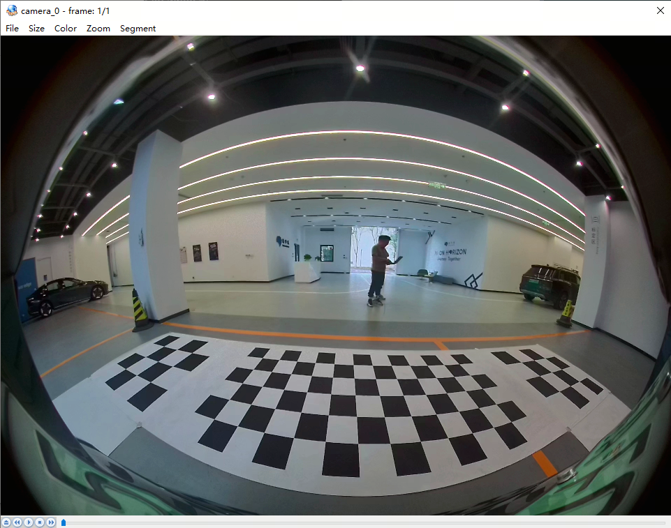
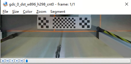
Original front-view image and its GDC-processed output:
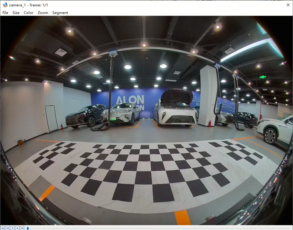
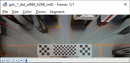
Original left-view image and its GDC-processed output:
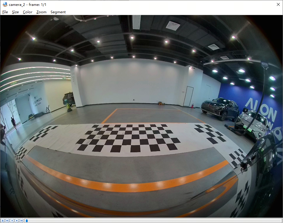
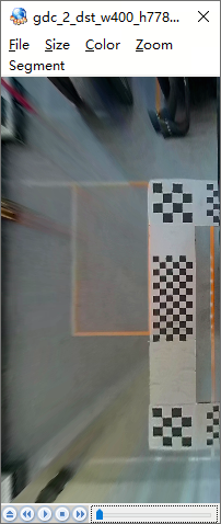
Original right-view image and its GDC-processed output:
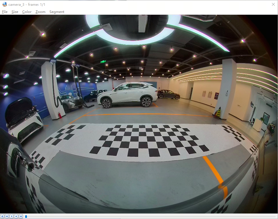
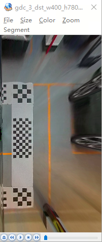
Final stitched output image:
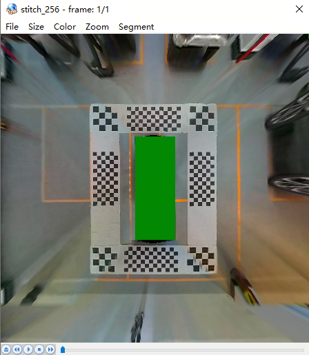
Corresponding ROI region division for stitching:
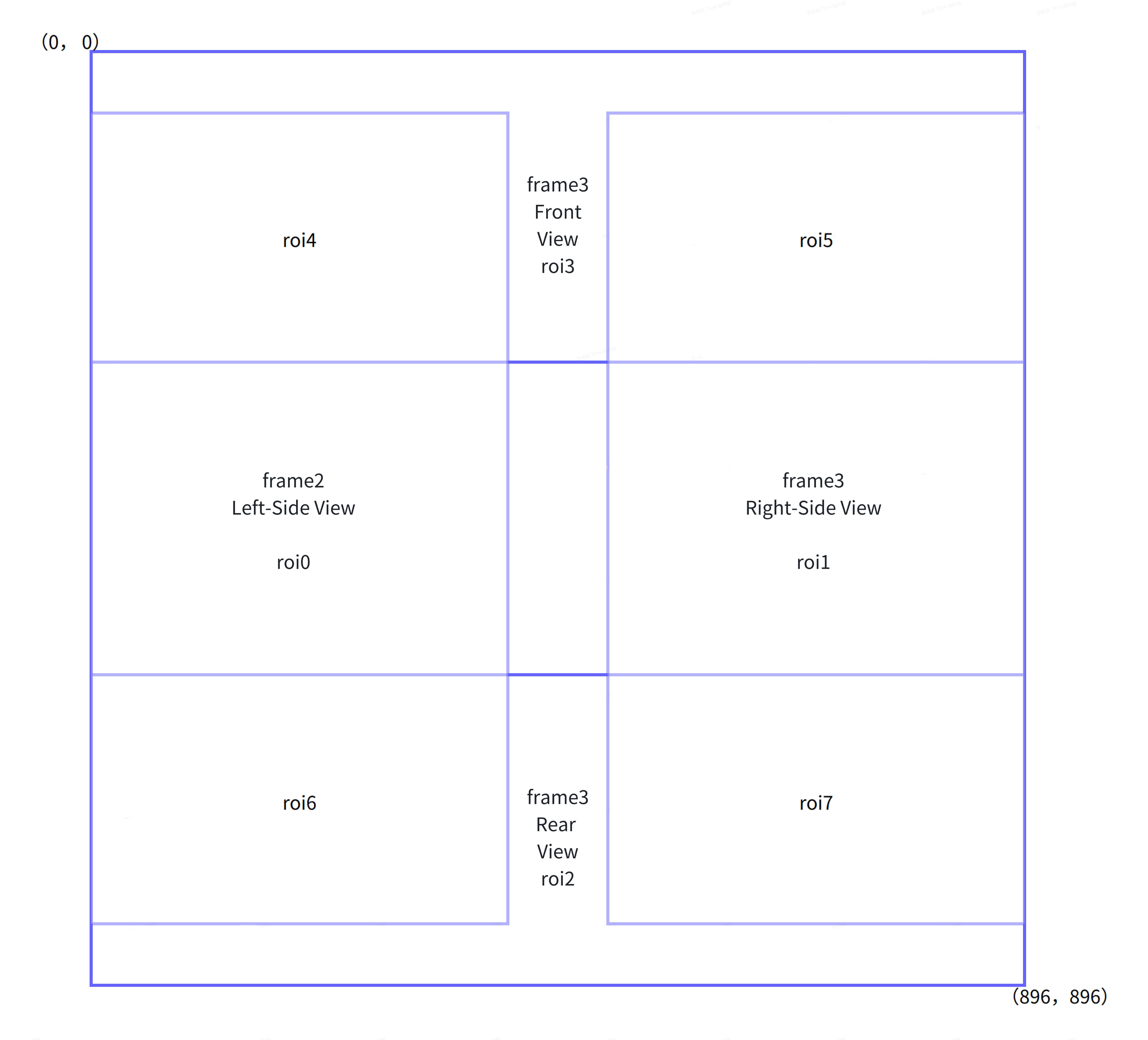
| ROI | Range | SRC0 | Start Point | Size | SRC1 | Start Point | Size | Destination Start | Mode | Direction |
|---|---|---|---|---|---|---|---|---|---|---|
| 0 | Left-view frame2 | frame 2 | (10, 0) | (390, 778) | (0, 16) | 3 Direct copy | ||||
| 1 | Right-view frame3 | frame 3 | (10, 0) | (390, 780) | (506, 14) | 3 Direct copy | ||||
| 2 | Rear-view frame0 | frame 0 | (0, 0) | (896, 298) | (0, 598) | 3 Direct copy | ||||
| 3 | Front-view frame1 | frame 1 | (4, 0) | (892, 298) | (0, 0) | 3 Direct copy | ||||
| 4 | Overlap between left and front views | frame 2 | (10, 0) | (390, 282) | frame 1 | (2, 16) | (390, 282) | (0, 16) | 1 Alpha blend | 0 Top-left |
| 5 | Overlap between right and front views | frame 3 | (10, 0) | (388, 284) | frame 1 | (508, 14) | (388, 284) | (506, 14) | 1 Alpha blend | 3 Top-right |
| 6 | Overlap between left and rear views | frame 2 | (10, 582) | (390, 196) | frame 0 | (0, 0) | (390, 196) | (0, 598) | 1 Alpha blend | 2 Bottom-left |
| 7 | Overlap between right and rear views | frame 3 | (10, 584) | (390, 196) | frame 0 | (506, 0) | (390, 196) | (506, 598) | 1 Alpha blend | 1 Bottom-right |
STITCH configuration parameters:
struct stitch_ch_attr inch_attr[4] = {
        {
                .width = 896,
                .height = 298,
                .strid = {896, 896},
                .rois = {
                        { .roi_index = 0, .roi_x = 0, .roi_y = 0, .roi_w = 0, .roi_h = 0  },
                        { .roi_index = 0, .roi_x = 0, .roi_y = 0, .roi_w = 0, .roi_h = 0  },
                        { .roi_index = 2, .roi_x = 0, .roi_y = 0, .roi_w = 0, .roi_h = 0  },
                        { .roi_index = 0, .roi_x = 0, .roi_y = 0, .roi_w = 0, .roi_h = 0  },
                        { .roi_index = 0, .roi_x = 0, .roi_y = 0, .roi_w = 0, .roi_h = 0  },
                        { .roi_index = 0, .roi_x = 0, .roi_y = 0, .roi_w = 0, .roi_h = 0  },
                        { .roi_index = 6, .roi_x = 0, .roi_y = 0, .roi_w = 0, .roi_h = 0  },
                        { .roi_index = 7, .roi_x = 506, .roi_y = 0, .roi_w = 0, .roi_h = 0  },
                        { .roi_index = 0, .roi_x = 0, .roi_y = 0, .roi_w = 0, .roi_h = 0  },
                        { .roi_index = 0, .roi_x = 0, .roi_y = 0, .roi_w = 0, .roi_h = 0  },
                        { .roi_index = 0, .roi_x = 0, .roi_y = 0, .roi_w = 0, .roi_h = 0  },
                        { .roi_index = 0, .roi_x = 0, .roi_y = 0, .roi_w = 0, .roi_h = 0  },

                }
        },
        {
                .width = 896,
                .height = 298,
                .strid = {896, 896},
                .rois = {
                        { .roi_index = 0, .roi_x = 0, .roi_y = 0, .roi_w = 0, .roi_h = 0  },
                        { .roi_index = 0, .roi_x = 0, .roi_y = 0, .roi_w = 0, .roi_h = 0  },
                        { .roi_index = 0, .roi_x = 0, .roi_y = 0, .roi_w = 0, .roi_h = 0  },
                        { .roi_index = 3, .roi_x = 4, .roi_y = 0, .roi_w = 0, .roi_h = 0  },
                        { .roi_index = 4, .roi_x = 2, .roi_y = 16, .roi_w = 0, .roi_h = 0  },
                        { .roi_index = 5, .roi_x = 508, .roi_y = 14, .roi_w = 0, .roi_h = 0  },
                        { .roi_index = 0, .roi_x = 0, .roi_y = 0, .roi_w = 0, .roi_h = 0  },
                        { .roi_index = 0, .roi_x = 0, .roi_y = 0, .roi_w = 0, .roi_h = 0  },
                        { .roi_index = 0, .roi_x = 0, .roi_y = 0, .roi_w = 0, .roi_h = 0  },
                        { .roi_index = 0, .roi_x = 0, .roi_y = 0, .roi_w = 0, .roi_h = 0  },
                        { .roi_index = 0, .roi_x = 0, .roi_y = 0, .roi_w = 0, .roi_h = 0  },
                        { .roi_index = 0, .roi_x = 0, .roi_y = 0, .roi_w = 0, .roi_h = 0  },

                }
        },
        {
                .width = 400,
                .height = 778,
                .strid = {400, 400},
                .rois = {
                        { .roi_index = 0, .roi_x = 10, .roi_y = 0, .roi_w = 0, .roi_h = 0  },
                        { .roi_index = 0, .roi_x = 0, .roi_y = 0, .roi_w = 0, .roi_h = 0  },
                        { .roi_index = 0, .roi_x = 0, .roi_y = 0, .roi_w = 0, .roi_h = 0  },
                        { .roi_index = 0, .roi_x = 0, .roi_y = 0, .roi_w = 0, .roi_h = 0  },
                        { .roi_index = 4, .roi_x = 10, .roi_y = 0, .roi_w = 0, .roi_h = 0  },
                        { .roi_index = 0, .roi_x = 0, .roi_y = 0, .roi_w = 0, .roi_h = 0  },
                        { .roi_index = 6, .roi_x = 10, .roi_y = 582, .roi_w = 0, .roi_h = 0  },
                        { .roi_index = 0, .roi_x = 0, .roi_y = 0, .roi_w = 0, .roi_h = 0  },
                        { .roi_index = 0, .roi_x = 0, .roi_y = 0, .roi_w = 0, .roi_h = 0  },
                        { .roi_index = 0, .roi_x = 0, .roi_y = 0, .roi_w = 0, .roi_h = 0  },
                        { .roi_index = 0, .roi_x = 0, .roi_y = 0, .roi_w = 0, .roi_h = 0  },
                        { .roi_index = 0, .roi_x = 0, .roi_y = 0, .roi_w = 0, .roi_h = 0  },

                }

        },
        {
                .width = 400,
                .height = 780,
                .strid = {400, 400},
                .rois = {
                        { .roi_index = 0, .roi_x = 0,  .roi_y = 0,   .roi_w = 0, .roi_h = 0  },
                        { .roi_index = 1, .roi_x = 10, .roi_y = 0,   .roi_w = 0, .roi_h = 0  },
                        { .roi_index = 0, .roi_x = 0,  .roi_y = 0,   .roi_w = 0, .roi_h = 0  },
                        { .roi_index = 0, .roi_x = 0,  .roi_y = 0,   .roi_w = 0, .roi_h = 0  },
                        { .roi_index = 0, .roi_x = 0,  .roi_y = 0,   .roi_w = 0, .roi_h = 0  },
                        { .roi_index = 5, .roi_x = 10, .roi_y = 0,   .roi_w = 0, .roi_h = 0  },
                        { .roi_index = 0, .roi_x = 0,  .roi_y = 0,   .roi_w = 0, .roi_h = 0  },
                        { .roi_index = 7, .roi_x = 10, .roi_y = 584, .roi_w = 0, .roi_h = 0  },
                        { .roi_index = 0, .roi_x = 0,  .roi_y = 0,   .roi_w = 0, .roi_h = 0  },
                        { .roi_index = 0, .roi_x = 0,  .roi_y = 0,   .roi_w = 0, .roi_h = 0  },
                        { .roi_index = 0, .roi_x = 0,  .roi_y = 0,   .roi_w = 0, .roi_h = 0  },
                        { .roi_index = 0, .roi_x = 0,  .roi_y = 0,   .roi_w = 0, .roi_h = 0  },

                }
        }
};

struct stitch_ch_attr och_attr = {
        .width = 896,
        .height = 896,
        .strid = {896, 896},
        .rois = {
                { .roi_index = 0, .roi_x =   0, .roi_y =  16, .roi_w = 390, .roi_h = 778  },
                { .roi_index = 1, .roi_x = 506, .roi_y =  14, .roi_w = 390, .roi_h = 780  },
                { .roi_index = 2, .roi_x =   0, .roi_y = 598, .roi_w = 896, .roi_h = 298  },
                { .roi_index = 3, .roi_x =   0, .roi_y =   0, .roi_w = 892, .roi_h = 298  },
                { .roi_index = 4, .roi_x =   0, .roi_y =  16, .roi_w = 390, .roi_h = 282  },
                { .roi_index = 5, .roi_x = 506, .roi_y =  14, .roi_w = 388, .roi_h = 284  },
                { .roi_index = 6, .roi_x =   0, .roi_y = 598, .roi_w = 390, .roi_h = 196  },
                { .roi_index = 7, .roi_x = 506, .roi_y = 598, .roi_w = 390, .roi_h = 196  },
                { .roi_index = 0, .roi_x =   0, .roi_y =   0, .roi_w =   0, .roi_h =   0  },
                { .roi_index = 0, .roi_x =   0, .roi_y =   0, .roi_w =   0, .roi_h =   0  },
                { .roi_index = 0, .roi_x =   0, .roi_y =   0, .roi_w =   0, .roi_h =   0  },
                { .roi_index = 0, .roi_x =   0, .roi_y =   0, .roi_w =   0, .roi_h =   0  },

        }
STITCH initialization
int32_t init_stitch(test_ctx_t *test_ctx)
{
        int32_t ret = 0, i;
        hbn_buf_alloc_attr_t alloc_attr = {0};
        char res_file_name[128] = {0};
        struct stat fileStat;

        ret = hbn_vnode_open(HB_STITCH, 0, -1, &test_ctx->sth_handle);```c
        if (ret < 0) {
                printf("STH vnode open fail\n");
                return -1;
        }

        memset(res_file_name, 0, sizeof(res_file_name));
        sprintf(res_file_name, "%s/%s", g_res_path, "alpha_lut_apa.bin");
        if(stat(res_file_name, &fileStat) != 0) {
                printf("Failed to get file stats. cfg file = %s\n", res_file_name);
                return -1;
        }

        ret = hb_mem_alloc_com_buf(fileStat.st_size, HB_MEM_USAGE_MAP_INITIALIZED |
                                                        HB_MEM_USAGE_PRIV_HEAP_2_RESERVERD | HB_MEM_USAGE_CPU_READ_OFTEN |
                                                        HB_MEM_USAGE_CPU_WRITE_OFTEN | HB_MEM_USAGE_CACHED, &alpha_buffer);
        if (ret < 0) {
                printf("hb_mem_alloc_com_buf alpha_lut faild, ret = %d\n", ret);
                return -1;
        }

        load_file_2_buff(res_file_name, (char *)alpha_buffer.virt_addr, fileStat.st_size);
        hb_mem_flush_buf_with_vaddr((uint64_t)alpha_buffer.virt_addr, fileStat.st_size);

        base_attr.alpha_lut.share_id = alpha_buffer.share_id;
        base_attr.alpha_lut.vaddr = (uint64_t)alpha_buffer.virt_addr;
        base_attr.alpha_lut.size = fileStat.st_size;

        ret = hbn_vnode_set_attr(test_ctx->sth_handle, &base_attr);
        if (ret < 0) {
                printf("STH vnode set attr fail\n");
                return -1;
        }

        for (i = 0; i < SENSOR_NUMS; i++) {
                ret = hbn_vnode_set_ichn_attr(test_ctx->sth_handle, i, &inch_attr[i]);
                if (ret < 0) {
                        printf("STH vnode set ichn attr fail\n");
                        return -1;
                }
        }

        ret = hbn_vnode_set_ochn_attr(test_ctx->sth_handle, 0, &och_attr);
        if (ret < 0) {
                printf("STH vnode set ochn attr fail\n");
                return -1;
        }

        memset(&alloc_attr, 0, sizeof(hbn_buf_alloc_attr_t));
        alloc_attr.buffers_num = 3;
        alloc_attr.is_contig = 1;
        alloc_attr.flags = (int64_t)((uint64_t)HB_MEM_USAGE_CPU_READ_OFTEN |
                        (uint64_t)HB_MEM_USAGE_CPU_WRITE_OFTEN | (uint64_t)HB_MEM_USAGE_MAP_INITIALIZED);
        alloc_attr.flags |= (uint64_t)HB_MEM_USAGE_CACHED;

        ret = hbn_vnode_set_ochn_buf_attr(test_ctx->sth_handle, 0, &alloc_attr);
        if (ret < 0) {
                printf("STH vnode set ochn buf attr fail\n");
                return -1;
        }

        ret = hbn_vnode_start(test_ctx->sth_handle);
        if (ret < 0) {
                printf("STH vnode start fail\n");
                return -1;
        }

        return 0;
}
2v imx219 + MIPI + CIM + ISP + PYM + STITCH stitching and encoding sample
This sample acquires two video streams from a pipeline consisting of two IMX219 sensors, CIM, ISP, PYM, and other modules, then stitches the two streams vertically via the STITCH CODEC module into a single H.264 file named cim-isp-pym-stitch.h264.
Test procedure:
After installing two IMX219 sensors, power on the device and execute the following commands:
sunrise@ubuntu:~$ cd /app/multimedia_demo/camsys_demo/sample_2v_219_stitch_codec/
sunrise@ubuntu:/app/multimedia_demo/camsys_demo/sample_2v_219_stitch_codec$ make
sunrise@ubuntu:/app/multimedia_demo/camsys_demo/sample_2v_219_stitch_codec$ ./sample_2v_219_stitch_codec
The generated cim-isp-pym-stitch.h264 file playback is shown below:
STITCH configuration parameters:
struct stitch_base_attr sth_base_attr = {
		  .mode = 2,
		  .roi_nums = 2,
		  .img_nums = 2,
		  .alpha_lut = {
			.share_id = 0,
			.vaddr = 0,
			.offset = 0,
			.size = 0
		  },
		  .beta_lut = {
			.share_id = 0,
			.vaddr = 0,
			.offset = 0,
			.size = 0
		  },
		  .blending = {{
			  .roi_index = 0,
			  .blending_mode = 3,
			  .direct = 0,
			  .uv_en = 1,
			  .src0_index = 0,
			  .src1_index = 1,
			  .margin = 0,
			  .margin_inv = 128,
			  .gain_src0_yuv = {256, 256, 256},
			  .gain_src1_yuv = {256, 256, 256}
			}, {
			  .roi_index = 1,
			  .blending_mode = 3,
			  .direct = 0,
			  .uv_en = 1,
			  .src0_index = 1,
			  .src1_index = 0,
			  .margin = 0,
			  .margin_inv = 128,
			  .gain_src0_yuv = {256, 256, 256},
			  .gain_src1_yuv = {256, 256, 256}
			}, {
			  .roi_index = 0,
			  .blending_mode = 0,
			  .direct = 0,
			  .uv_en = 0,
			  .src0_index = 0,
			  .src1_index = 0,
			  .margin = 0,
			  .margin_inv = 0,
			  .gain_src0_yuv = {0, 0, 0},
			  .gain_src1_yuv = {0, 0, 0}
			}, {
			  .roi_index = 0,
			  .blending_mode = 0,
			  .direct = 0,
			  .uv_en = 0,
			  .src0_index = 0,
			  .src1_index = 0,
			  .margin = 0,
			  .margin_inv = 0,
			  .gain_src0_yuv = {0, 0, 0},
			  .gain_src1_yuv = {0, 0, 0}
			}, {
			  .roi_index = 0,
			  .blending_mode = 0,
			  .direct = 0,
			  .uv_en = 0,
			  .src0_index = 0,
			  .src1_index = 0,
			  .margin = 0,
			  .margin_inv = 0,
			  .gain_src0_yuv = {0, 0, 0},
			  .gain_src1_yuv = {0, 0, 0}
			}, {
			  .roi_index = 0,
			  .blending_mode = 0,
			  .direct = 0,
			  .uv_en = 0,
			  .src0_index = 0,
			  .src1_index = 0,
			  .margin = 0,
			  .margin_inv = 0,
			  .gain_src0_yuv = {0, 0, 0},
			  .gain_src1_yuv = {0, 0, 0}
			}, {
			  .roi_index = 0,
			  .blending_mode = 0,
			  .direct = 0,
			  .uv_en = 0,
			  .src0_index = 0,
			  .src1_index = 0,
			  .margin = 0,
			  .margin_inv = 0,
			  .gain_src0_yuv = {0, 0, 0},
			  .gain_src1_yuv = {0, 0, 0}
			}, {
			  .roi_index = 0,
			  .blending_mode = 0,
			  .direct = 0,
			  .uv_en = 0,
			  .src0_index = 0,
			  .src1_index = 0,
			  .margin = 0,
			  .margin_inv = 0,
			  .gain_src0_yuv = {0, 0, 0},
			  .gain_src1_yuv = {0, 0, 0}
			}, {
			  .roi_index = 0,
			  .blending_mode = 0,
			  .direct = 0,
			  .uv_en = 0,
			  .src0_index = 0,
			  .src1_index = 0,
              .margin = 0,
			  .margin_inv = 0,
			  .gain_src0_yuv = {0, 0, 0},
			  .gain_src1_yuv = {0, 0, 0}
			}, {
			  .roi_index = 0,
			  .blending_mode = 0,
			  .direct = 0,
			  .uv_en = 0,
			  .src0_index = 0,
			  .src1_index = 0,
			  .margin = 0,
			  .margin_inv = 0,
			  .gain_src0_yuv = {0, 0, 0},
			  .gain_src1_yuv = {0, 0, 0}
			}, {
			  .roi_index = 0,
			  .blending_mode = 0,
			  .direct = 0,
			  .uv_en = 0,
			  .src0_index = 0,
			  .src1_index = 0,
			  .margin = 0,
			  .margin_inv = 0,
			  .gain_src0_yuv = {0, 0, 0},
			  .gain_src1_yuv = {0, 0, 0}
			}, {
			  .roi_index = 0,
			  .blending_mode = 0,
			  .direct = 0,
			  .uv_en = 0,
			  .src0_index = 0,
			  .src1_index = 0,
			  .margin = 0,
			  .margin_inv = 0,
			  .gain_src0_yuv = {0, 0, 0},
			  .gain_src1_yuv = {0, 0, 0}
			}}
};

struct stitch_ch_attr sth_inch_attr[] = {
           {
			.width = 1920,
			.height = 1080,
			.strid = {1920, 1920},
			.rois = {{
				.roi_index = 0,
				.roi_x = 0,
				.roi_y = 0,
				.roi_w = 1920,
				.roi_h = 1080
			  }, {
				.roi_index = 1,
				.roi_x = 0,
				.roi_y = 0,
				.roi_w = 1920,
				.roi_h = 1080
			  },
			}
		  }, {
			.width = 1920,
			.height = 1080,
			.strid = {1920, 1920},
			.rois = {{
				.roi_index = 0,
				.roi_x = 0,
				.roi_y = 0,
				.roi_w = 1920,
				.roi_h = 1080
			  }, {
				.roi_index = 1,
				.roi_x = 0,
				.roi_y = 0,
				.roi_w = 1920,
				.roi_h = 1080
			  },
			}
		  }, {
			.width = 0,
			.height = 0,
			.strid = {0, 0},
		  }, {
			.width = 0,
			.height = 0,
			.strid = {0, 0},
		  }
};

struct stitch_ch_attr sth_och_attr = {
		  .width = 1920,
		  .height = 2160,
		  .strid = {1920, 1920},
		  .rois = {{
			  .roi_index = 0,
			  .roi_x = 0,
			  .roi_y = 0,
			  .roi_w = 1920,
			  .roi_h = 1080
			}, {
			  .roi_index = 1,
			  .roi_x = 0,
			  .roi_y = 1080,
			  .roi_w = 1920,
			  .roi_h = 1080
			},
		  }
};
Create a vflow pipeline:
	int i = 0;
	ret = hbn_vflow_create(&vflow_fd[i]);
	if (ret < 0) {
		printf("hbn_vflow_create[%d]:%d error\n", i, __LINE__);
		goto err;
	}

	ret = hbn_camera_create(&cam_cfg[i], &cam_vnode_fd[i]);
	if (ret < 0) {
		printf("hbn_camera_create[%d]:%d error\n", i, __LINE__);
		goto err1;
	}

	vin_vnode_fd[i] = vin_vnode_create(&vin_attr[i]);
	if (vin_vnode_fd[i] < 0) {
		ret = (int32_t)vin_vnode_fd[i];
		printf("vin_vnode_init[%d]:%d error\n", i, __LINE__);
		goto err1;
	}

	ret = hbn_vflow_add_vnode(vflow_fd[i], vin_vnode_fd[i]);
	if (ret < 0) {
		printf("hbn_vflow_add_vnode[%d]:%d error\n", i, __LINE__);
		goto err1;
	}

	isp_vnode_fd[i] = isp_vnode_create(&isp_cfg[i]);
	if (isp_vnode_fd[i] < 0) {
		ret = (int32_t)isp_vnode_fd[i];
		printf("isp_vnode_init[%d]:%d error\n", i, __LINE__);
		goto err1;
	}

	ret = hbn_vflow_add_vnode(vflow_fd[i], isp_vnode_fd[i]);
	if (ret < 0) {
		printf("hbn_vflow_add_vnode[%d]:%d error\n", i, __LINE__);
		goto err1;
	}

	ynr_vnode_fd[i] = ynr_vnode_create(&ynr_info[i]);
	if (ynr_vnode_fd[i] < 0) {
		ret = (int32_t)ynr_vnode_fd[i];
		printf("ynr_vnode_init[%d]:%d error\n", i, __LINE__);
		goto err1;
	}

	ret = hbn_vflow_add_vnode(vflow_fd[i], ynr_vnode_fd[i]);
	if (ret < 0) {
		printf("hbn_vflow_add_vnode[%d]:%d error\n", i, __LINE__);
		goto err1;
	}

	pym_vnode_fd[i] = pym_vnode_create(&pym_cfg[i]);
	if (pym_vnode_fd[i] < 0) {
		ret = (int32_t)pym_vnode_fd[i];
		printf("pym_vnode_init[%d]:%d error\n", i, __LINE__);
		goto err1;
	}

	ret = hbn_vflow_add_vnode(vflow_fd[i], pym_vnode_fd[i]);
	if (ret < 0) {
		printf("hbn_vflow_add_vnode[%d]:%d error\n", i, __LINE__);
		goto err1;
	}

	sth_vnode_fd = sth_vnode_create();
	if (sth_vnode_fd < 0) {
		ret = (int32_t)sth_vnode_fd;
		printf("sth_vnode_init[%d]:%d error\n", i, __LINE__);
		goto err1;
	}

	ret = hbn_vflow_add_vnode(vflow_fd[i], sth_vnode_fd);
	if (ret < 0) {
		printf("hbn_vflow_add_vnode[%d]:%d error\n", i, __LINE__);
		goto err1;
	}

	ret = hbn_camera_attach_to_vin(cam_vnode_fd[i], vin_vnode_fd[i]);
	if (ret < 0) {
		printf("hbn_vflow_bind_vnode[%d]:%d error\n", i, __LINE__);
		goto err1;
	}

	ret = hbn_vflow_bind_vnode(vflow_fd[i], vin_vnode_fd[i], 0, isp_vnode_fd[i], 0);
	if (ret < 0) {
		printf("hbn_vflow_bind_vnode[%d]:%d error\n", i, __LINE__);
		goto err1;
	}
```Create another vflow and bind both vflows to the same stitch:
```c
	i = 1;
	ret = hbn_vflow_create(&vflow_fd[i]);
	if (ret < 0) {
		printf("hbn_vflow_create[%d]:%d error\n", i, __LINE__);
		goto err1;
	}

	ret = hbn_camera_create(&cam_cfg[i], &cam_vnode_fd[i]);
	if (ret < 0) {
		printf("hbn_camera_create[%d]:%d error\n", i, __LINE__);
		goto err1;
	}

	vin_vnode_fd[i] = vin_vnode_create(&vin_attr[i]);
	if (vin_vnode_fd[i] < 0) {
		ret = (int32_t)vin_vnode_fd[i];
		printf("vin_vnode_init[%d]:%d error\n", i, __LINE__);
		goto err1;
	}

	ret = hbn_vflow_add_vnode(vflow_fd[i], vin_vnode_fd[i]);
	if (ret < 0) {
		printf("hbn_vflow_add_vnode[%d]:%d error\n", i, __LINE__);
		goto err1;
	}

	isp_vnode_fd[i] = isp_vnode_create(&isp_cfg[i]);
	if (isp_vnode_fd[i] < 0) {
		ret = (int32_t)isp_vnode_fd[i];
		printf("isp_vnode_init[%d]:%d error\n", i, __LINE__);
		goto err1;
	}

	ret = hbn_vflow_add_vnode(vflow_fd[i], isp_vnode_fd[i]);
	if (ret < 0) {
		printf("hbn_vflow_add_vnode[%d]:%d error\n", i, __LINE__);
		goto err1;
	}

	ynr_vnode_fd[i] = ynr_vnode_create(&ynr_info[i]);
	if (ynr_vnode_fd[i] < 0) {
		ret = (int32_t)ynr_vnode_fd[i];
		printf("ynr_vnode_init[%d]:%d error\n", i, __LINE__);
		goto err1;
	}

	ret = hbn_vflow_add_vnode(vflow_fd[i], ynr_vnode_fd[i]);
	if (ret < 0) {
		printf("hbn_vflow_add_vnode[%d]:%d error\n", i, __LINE__);
		goto err1;
	}
	pym_vnode_fd[i] = pym_vnode_create(&pym_cfg[i]);;
	if (pym_vnode_fd[i] < 0) {
		ret = (int32_t)pym_vnode_fd[i];
		printf("pym_vnode_init[%d]:%d error\n", i, __LINE__);
		goto err1;
	}

	ret = hbn_vflow_add_vnode(vflow_fd[i], pym_vnode_fd[i]);
	if (ret < 0) {
		printf("bn_vflow_add_vnode[%d]:%d error\n", i, __LINE__);
		goto err1;
	}

	ret = hbn_vflow_add_vnode(vflow_fd[i], sth_vnode_fd);
	if (ret < 0) {
		printf("hbn_vflow_add_vnode[%d]:%d error\n", i, __LINE__);
		goto err1;
	}

	ret = hbn_camera_attach_to_vin(cam_vnode_fd[i], vin_vnode_fd[i]);
	if (ret < 0) {
		printf("hbn_camera_attach_to_vin[%d]:%d error\n", i, __LINE__);
		goto err1;
	}

	ret = hbn_vflow_bind_vnode(vflow_fd[i], vin_vnode_fd[i], 0, isp_vnode_fd[i], 0);
	if (ret < 0) {
		printf("hbn_vflow_bind_vnode[%d]:%d error\n", i, __LINE__);
		goto err1;
	}

	ret = hbn_vflow_bind_vnode(vflow_fd[i], isp_vnode_fd[i], 1, ynr_vnode_fd[i], 0);
	if (ret < 0) {
		printf("hbn_vflow_bind_vnode[%d]:%d error\n", i, __LINE__);
		goto err1;
	}

	ret = hbn_vflow_bind_vnode(vflow_fd[i], ynr_vnode_fd[i], 1, pym_vnode_fd[i], 0);
	if (ret < 0) {
		printf("hbn_vflow_bind_vnode[%d]:%d error\n", i, __LINE__);
		goto err1;
	}

	ret = hbn_vflow_bind_vnode(vflow_fd[i], pym_vnode_fd[i], 0, sth_vnode_fd, 1);
	if (ret < 0) {
		printf("hbn_vflow_bind_vnode[%d]:%d error\n", i, __LINE__);
		goto err1;
	}
Configure the CODEC encoding module:
	//config codec
	ret = codec_config_param(&context, MEDIA_CODEC_ID_H264, sth_och_attr.width, sth_och_attr.height);
	if (ret < 0) {
		printf("codec_config_param error!!!\n");
		goto err1;
	}

	ret = codec_init(&context);
	if (ret < 0) {
		printf("codec_init error!!!\n");
		goto err1;
	}

	ret = codec_start(&context);
	if (ret < 0) {
		printf("codec_init error!!!\n");
		goto err2;
	}

	h264fd = fopen(H264_FNAME, "w+");
    if (h264fd == NULL) {
        printf("open(%s) fail", H264_FNAME);
		ret = -1;
        goto err3;
    }

	ret = hbn_vflow_start(vflow_fd[0]);
	ret |= hbn_vflow_start(vflow_fd[1]);
	if (ret < 0) {
		printf("codec_init error!!!\n");
		goto err3;
	}
Continuously fetch frames, send them to the CODEC for encoding, then retrieve encoded frames from the CODEC and save them as an H.264 file:
	while (imgframe.cnt < 30 * TIMEOUT) {
		ret = hbn_vnode_getframe(sth_vnode_fd, 0, 1000, &imgframe.vnode_buffer);
		printf("sth_worker, ret = %d\n", ret);
		if (ret == 0) {
			ret = codec_set_input(&context, &imgframe);
			if (ret < 0) {
				printf("codec_set_input error!!!\n");
				goto err4;
			}

			ret = codec_get_output(&context, &imgframe);
			if (ret < 0) {
				printf("codec_get_output error!!!\n");
				goto err4;
			}

            ret = write_output_h264(&imgframe, h264fd);
			if (ret < 0) {
				printf("write_output_h264 error!!!\n");
				goto err4;
			}

			ret = codec_release_output(&context, &imgframe);
			if (ret < 0) {
				printf("codec_release_output error!!!\n");
				goto err4;
			}

			hbn_vnode_releaseframe(sth_vnode_fd, 0, &imgframe.vnode_buffer);
		} else {
			printf("hbn_vnode_getframe fail, ret = %d\n", ret);
			goto err4;
		}

		imgframe.cnt++;
	}
V4L2 Sample
imx219 + MIPI + CIM + ISP + PYM:
v4l2-ctl -d 0 --set-fmt-video=width=1920,height=1080,pixelformat=NV12 --stream-mmap --stream-count=120 --stream-to=/userdata/test.yuv
imx219 + MIPI + CIM + ISP + GDC:
The v4l2 GDC application currently cannot generate config bin files from JSON files, so v4l2 GDC testing can only be performed using pre-generated config bin files.
Compared with the original v4l2 stream capture code, the v4l2 GDC stream capture code requires the following additional configurations:

# Need to add GDC input image width and height parameter configuration
if (TestContext[i].gdc_cfg) {
    TestContext[i].pic_width = 1920;
    TestContext[i].pic_height = 1080;
    TestContext[i].in_pic_width = 1920;  // Newly added input image width
    TestContext[i].in_pic_height = 1080; // Newly added input image height
}

# Need to add GDC config configuration
// Allocate memory for GDC config bin
int map_gdc_config_buffer(hb_mem_common_buf_t *hb_common_buf, uint32_t size)
{
    int64_t alloc_flags = 0;
    int ret;

    alloc_flags = HB_MEM_USAGE_PRIV_HEAP_2_RESERVED | HB_MEM_USAGE_CPU_READ_OFTEN | HB_MEM_USAGE_CPU_WRITE_OFTEN | HB_MEM_USAGE_CACHED;
    memset(hb_common_buf, 0, sizeof(hb_mem_common_buf_t));
    ret = hb_mem_alloc_com_buf(size, alloc_flags, hb_common_buf);
    if (ret < 0) {
        vio_gtest_err("hb_mem_alloc_com_buf size %u failed \n", size);
        return ret;
    }

    return 0;
}

// ioctl interface to send configuration to GDC v4l2 driver
int v4l2_set_ext_ctrl(int fd, uint32_t cmd, void *arg)
{
    int rc;
    struct v4l2_ext_controls ext_ctrl = {0};
    struct v4l2_ext_control ctrl = {0};

    ext_ctrl.controls = &ctrl;
    ext_ctrl.controls->id = cmd;
    ext_ctrl.controls->ptr = arg;
    ext_ctrl.count = 1;

    rc = ioctl(fd, VIDIOC_S_EXT_CTRLS, &ext_ctrl);
    if (rc < 0)
        vio_gtest_err("%s, cmd=%d, rc=%d\n", strerror(errno), cmd, rc);
    return rc;
}

int v4l2_gdc_init(vpm_test_context *ptc)
{
    int fd, ret;
    FILE *file = NULL;
    struct stat fileStat;
    hb_mem_common_buf_t hb_common_buf;
    gdc_config_t gdc_user_cfg;
    work_info_t *winfo = &ptc->work_info;

    if (!ptc->gdc_cfg || !winfo->priv_fd)
        return -1;

    file = fopen(ptc->gdc_cfg, "r");
    if (file == NULL) {
        perror("Error opening file\n");
        return -1;
    }
    // Get GDC config bin size
    ret = fstat(fileno(file), &fileStat);
    if (ret) {
        perror("Error getting file status");
        goto err;
    }

    vio_gtest_info("File size: %ld bytes\n", fileStat.st_size);
    // Allocate memory to store GDC config bin
    ret = map_gdc_config_buffer(&hb_common_buf, fileStat.st_size);
    if (ret)
        goto err;
    // Copy GDC config bin content into the allocated memory
    if (fread(hb_common_buf.virt_addr, 1, fileStat.st_size, file) != fileStat.st_size) {
        vio_gtest_err("failed to read gdc config file!\n");
        ret = -1;
        goto err;
    }
    vio_gtest_info("gdc config bin buffer phy_addr:%p virt_addr:%p size:%d\n",
        hb_common_buf.phys_addr, hb_common_buf.virt_addr, hb_common_buf.size);

    ret = hb_mem_flush_buf_with_vaddr((uint64_t)hb_common_buf.virt_addr, fileStat.st_size);
    if (ret) {
        vio_gtest_err("failed to hb_mem_flush_buf_with_vaddr!\n");
        goto err;
    }

    gpm[winfo->pipe_id].gdc_config.config_addr = (uint64_t)hb_common_buf.virt_addr;
    gpm[winfo->pipe_id].gdc_config.config_size = hb_common_buf.size;
    // GDC input image width and height
    gpm[winfo->pipe_id].gdc_config.output_width = ptc->pic_width;
    gpm[winfo->pipe_id].gdc_config.output_height = ptc->pic_height;
    gpm[winfo->pipe_id].gdc_config.output_stride = ALIGN_UP(ptc->pic_width, STRIDE_ALIGN);
    // GDC output image width and height
    gpm[winfo->pipe_id].gdc_config.input_width = ptc->in_pic_width;
    gpm[winfo->pipe_id].gdc_config.input_height = ptc->in_pic_height;
    gpm[winfo->pipe_id].gdc_config.input_stride = ALIGN_UP(ptc->in_pic_width, STRIDE_ALIGN);

    gpm[winfo->pipe_id].gdc_config.div_width = 0;
    gpm[winfo->pipe_id].gdc_config.div_height = 0;
    gpm[winfo->pipe_id].gdc_config.sequential_mode = 0;
    gpm[winfo->pipe_id].gdc_config.total_planes = 2;

    gpm[winfo->pipe_id].binary_ion_id = hb_common_buf.share_id;
    gpm[winfo->pipe_id].binary_offset = hb_common_buf.offset;

    gpm[winfo->pipe_id].magicNumber = 0x12345678;

    // Send configuration to GDC v4l2 driver
    ret = v4l2_set_ext_ctrl(winfo->priv_fd, V4L2_CID_DR_GDC_ATTR, &gpm[winfo->pipe_id]);
    if (ret) {
        vio_gtest_err("v4l2_set_ext_ctrl error!!!\n");
        goto err;
    }

err:
    fclose(file);
    return ret;

}

# Release GDC config bin
void v4l2_gdc_deinit (vpm_test_context *ptc)
{
    work_info_t *winfo = &ptc->work_info;
    hb_mem_free_buf_with_vaddr((uint64_t)gpm[winfo->pipe_id].gdc_config.config_addr);
}