Display Subsystem
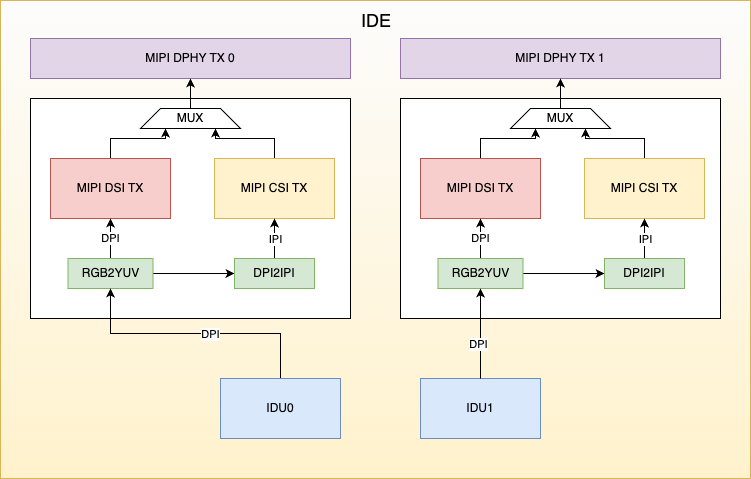
IDE Architecture Diagram
IDE (Image Display Engine) includes an Image Display Unit (IDU), and image data output modules (MIPI CSI2 Device and MIPI DSI). The IDU fetches image data from memory for processing. Within the IDE, pixel format conversion and pixel structure conversion are supported, enabling the IDU output data to be transmitted via either MIPI DSI or MIPI CSI2 Device. The MIPI DSI and MIPI CSI2 Device controllers share a single MIPI D-PHY.
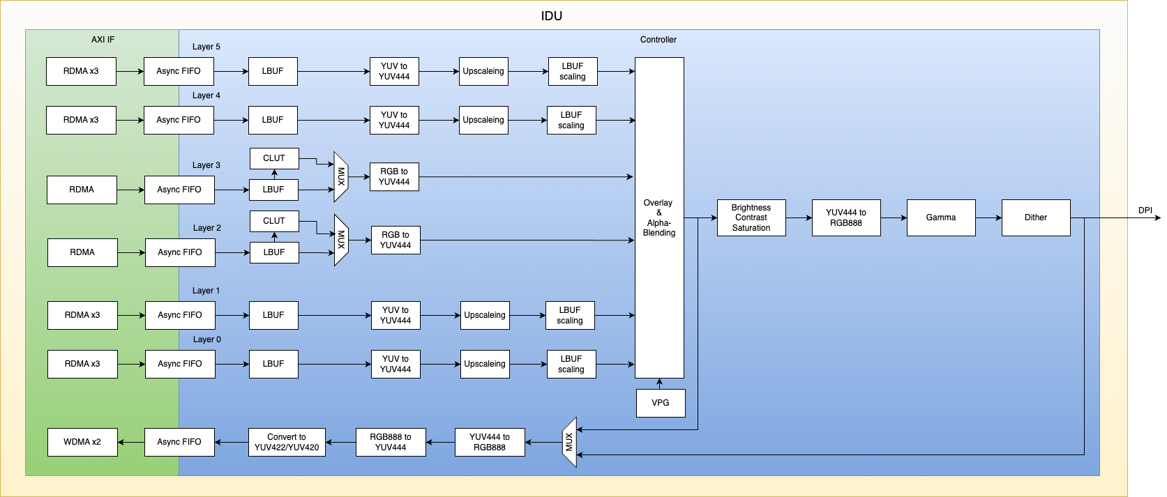
IDU Architecture Diagram
The S100 integrates two IDU (Image Display Unit) hardware modules that are functionally identical.
Features Supported by IDU
-
The IDU module supports a total of 6 channels: Channels 0, 1, 4, and 5 serve as YUV layer channels, while channels 2 and 3 serve as RGB layer channels.
-
Each channel supports a maximum input resolution of 2880x2160.
-
All 6 channels support the Crop function, including configurable crop width/height and configurable crop top-left vertex coordinates.
-
YUV layers support the following formats:
UYVY Interleaved YUV422, VYUY Interleaved YUV422, YUYV Interleaved YUV422, YVYU Interleaved YUV422,
UV Semi-planar YUV422, VU Semi-planar YUV422, UV Semi-planar YUV420, VU Semi-planar YUV420,
Planar YUV422 (YU YV), Planar YUV422 (YV YU), Planar YUV420 (YU YV), Planar YUV420 (YV YU). -
RGB layers support the following formats:
8-bpp (CLUT, color lookup table), RGB565, Unpacked RGB888, Packed RGB888, ARGB, RGBA.
Among these, the 8-bpp format has no endianness issues; RGB565, Unpacked RGB888, and Packed RGB888 support only little-endian format; ARGB and RGBA support both little-endian and big-endian formats. (Note: Most common image formats use big-endian.) -
Supports overlaying (Overlay & Alpha-Blending, Key-color) of 6 layers with a background layer and a hardware cursor (HW Cursor), with configurable alpha values and overlay layer priorities.
-
YUV layers support upscaling, with a maximum scaling factor of 6x.
-
Output supports Color Adjustment (contrast, saturation, brightness, hue, gamma, and dithering).
-
Supports write-back functionality, with supported write-back formats including:
UYVY, VYUY, YUYV, YVYU, NV12, NV21, Unpacked RGB888. -
Output interfaces support MIPI-CSI-TX or MIPI DSI.
-
IDU output supports RGB888, RGB565, and RGB666, and can be converted via an RGB2YUV module into YUV422 or YCbCr formats.
-
Maximum pixel rate: 600 MHz; maximum output resolution: 3840x2160.
Features Supported by MIPI TX
-
The MIPI CSI TX controller complies with CSI 2.0 specification.
-
The MIPI DSI controller complies with DSI 1.2 specification.
-
The IDE provides two MIPI TX output paths, configurable as either CSI or DSI output; both controllers share a single D-PHY.
-
The MIPI D-PHY supports up to 4 lanes at a maximum speed of 2.5 Gbps per lane.
Debugging Methods for IDU
IDU Debug Nodes
- Enable register configuration trace logs:
echo 1 > /sys/kernel/debug/idu_hw0/trace_log

echo 1 > /sys/kernel/debug/idu_hw1/trace_log
- View IDU configuration information:
cat /sys/kernel/debug/idu_hw0/config

cat /sys/kernel/debug/idu_hw1/config
Enabling IDU Driver Debug Logs
echo -n "file hb_idu_hw.c +p" > /sys/kernel/debug/dynamic_debug/control
Debugging Methods for MIPI CSI TX
MIPI CSI TX Debug Nodes
- View MIPI CSI TX configuration information:
cat /sys/kernel/debug/mipi_csi_dev0/config

cat /sys/kernel/debug/mipi_csi_dev1/config
Enabling MIPI CSI TX Driver Debug Logs
echo -n "file hb_mipi_csi_device_debug.c +p" > /sys/kernel/debug/dynamic_debug/control
Debugging Methods for MIPI DSI
MIPI DSI Debug Nodes
- View MIPI DSI configuration information:
cat /sys/kernel/debug/mipi_dsi_host0/config

cat /sys/kernel/debug/mipi_dsi_host1/config
Enabling MIPI DSI Driver Debug Logs
echo -n "file hb_mipi_dsi_host_ops.c +p" > /sys/kernel/debug/dynamic_debug/control