1.1.3 RDK Ultra
Important: The RDK Ultra is available for sale only in Mainland China.
For related download resources, please refer to: Download Resources Summary
Includes specification sheets, schematics, mechanical drawings, 3D drawings, reference design materials, and other complete hardware documentation.
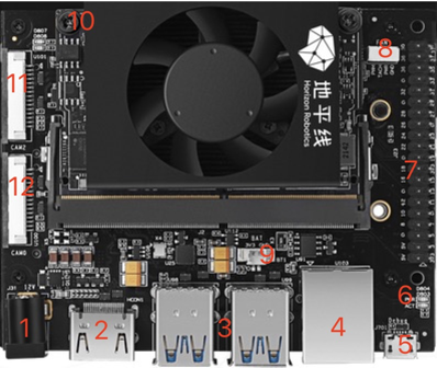
The RDK Ultra development kit provides a variety of peripheral interfaces, including Ethernet, USB, HDMI, MIPI CSI, and a 40-pin header, making it convenient for users to experience, develop, and test the kit's functions. The interface layout is as follows:
| No. | Interface Function | No. | Interface Function | No. | Interface Function |
|---|---|---|---|---|---|
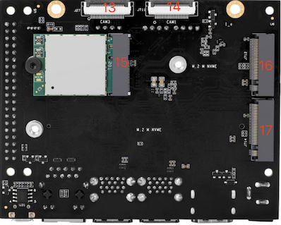
| 1 | Power connector | 7 | 40-pin header | 13 | CAM3 interface, 24PIN, 4lane |
| 2 | HDMI display interface | 8 | PWM fan interface | 14 | CAM1 interface, 24PIN, 4lane |
| 3 | 4x USB 3.0 interfaces | 9 | RTC battery interface | 15 | Wi-Fi module interface, PCIe M.2-E |
| 4 | Gigabit Ethernet port | 10 | Function control interface | 16 | SSD interface, PCIe M.2-M |
| 5 | Debug interface | 11 | CAM2 interface, 15PIN, 2lane | 17 | SSD interface, PCIe M.2-M |
| 6 | Status indicator LED | 12 | CAM0 interface, 15PIN, 2lane |
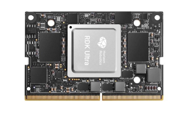
Core Module Interface
The RDK Ultra Module core board hardware interface is compatible with the Jetson Orin series development boards, allowing users to quickly integrate and productize their solutions.
Power Interface
The RDK Ultra development board is powered via a DC connector. It is recommended to use the included power adapter, or an adapter with at least 12V/5A output. When the power is connected, the red power indicator LED (interface 6) will light up, indicating normal power supply.
Do not use a computer USB port to power the board, as insufficient power may cause abnormal shutdowns or repeated reboots.
Debug UART
The RDK Ultra development board provides a debug interface (interface 5), using a CH340 chip to convert the core module’s UART to USB. Users can use this interface for various debugging tasks. Configure your serial tool with the following parameters:
- Baud rate: 921600
- Data bits: 8
- Parity: None
- Stop bits: 1
- Flow Control: None
Usually, the CH340 driver needs to be installed on your computer the first time you use this interface. Search for CH340 serial driver to download and install.
Wired Ethernet
The board provides a Gigabit Ethernet interface (interface 4), supporting 1000BASE-T and 100BASE-T standards. By default, it uses static IP mode with the address 192.168.1.10. To confirm the board’s IP address, log in via serial and use the ifconfig command to check the eth0 configuration.
HDMI Interface
The RDK Ultra development board provides an HDMI display interface (interface 2), supporting up to 1080P resolution. After powering on, the board outputs the Ubuntu graphical interface via HDMI. With specific sample programs, the HDMI interface also supports previewing camera and video stream images.
Currently, only the 1080p60 display mode is supported; more modes will be available in future software versions.
USB Interface
The RDK Ultra development board provides four standard USB 3.0 interfaces (interface 3), supporting simultaneous connection of four USB devices. Note that the USB interfaces only support Host mode.
USB Camera
Video: https://www.bilibili.com/video/BV1rm4y1E73q/?p=6
The board’s USB Type-A interface supports USB cameras. The system will automatically detect connected USB cameras and create the device node /dev/video8.
MIPI CSI
The RDK Ultra development board provides four camera interfaces (CAM 0~3), supporting simultaneous connection of four MIPI camera modules. Notes:
- CAM 0/2 (interfaces 11/12) use 15-pin FPC connectors, supporting Raspberry Pi OV5647, IMX219, IMX477, etc.
- CAM 1/3 (interfaces 13/14) use 24-pin FPC connectors, supporting F37, GC4663, IMX415, etc.
Camera module specifications:
| No. | Sensor | Resolution | FOV | I2C Address |
|---|---|---|---|---|
| 1 | GC4663 | 4MP | H:104 V:70 D:113 | 0x29 |
| 2 | JXF37 | 2MP | H:62 V:37 D:68 | 0x40 |
| 3 | IMX219 | 8MP | H:62 V:37 D:68 | 0x10 |
| 4 | IMX477 | 12MP | H:62 V:37 D:68 | 0x1a |
| 5 | OV5647 | 5MP | H:62 V:37 D:68 | 0x36 |
For camera module purchasing, refer to the community accessories page: Purchase Link.
Important: Do not plug or unplug camera modules while the board is powered on, as this may damage the camera modules.
Wi-Fi Antenna Interface
The board comes pre-installed with a Wi-Fi module and antenna (interface 15).
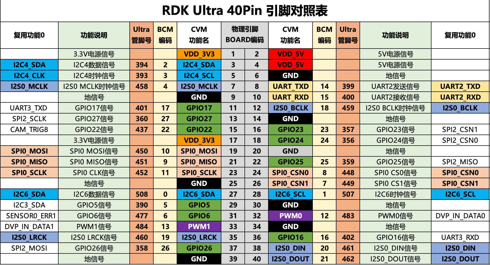
40-pin Header Interface
The RDK Ultra development board provides a 40-pin header (interface 7), supporting GPIO, UART, I2C, SPI, I2S, and more. Detailed pin definitions and multiplexing are as follows:
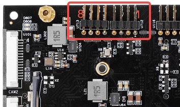
Function Control Interface
The RDK Ultra development board provides a function control interface (interface 10) for controlling the core module’s functional modes. Pin definitions:
| Pin No. | Pin Name | Function Description | Usage |
|---|---|---|---|
| 1 | WAKE_UP | Wake up the board | Short to GND with jumper cap |
| 2 | GND | Ground | GND |
| 3 | FC_REC | Force recovery mode | Short to GND with jumper cap |
| 4 | GND | Ground | GND |
| 5 | SYS_RST | System reset | Short to GND with jumper cap, then remove |
| 6 | GND | Ground | GND |
| 7 | PWR_EN | Power enable signal | Short to GND with jumper cap to power off |
| 8 | GND | Ground | GND |