8.2 Interfaces, Peripherals, and Drivers
40-pin GPIO Interface
Q1: Does the development board support using VDD_5V from the 40PIN header as a power input?
A: Supported on development board versions V1.2 and above. You can usually confirm the version by checking the silkscreen information on the PCB. Please operate with caution and ensure your board version supports this feature—incorrect power supply may cause hardware damage.
Q2: Can I control the 40-pin GPIO interface using C/C++?
A: Yes, it is supported. Refer to relevant articles and code samples in the Horizon Developer Community, such as:
- Sunrise X3Pi WiringPi (a C/C++ GPIO library adapted for RDK X3)
- Check the official documentation for your RDK model for chapters on GPIO development, which usually provide low-level operation methods or recommended libraries.
Serial Port
Q3: No debug serial log output after powering on the board. What should I do?
A: Please troubleshoot as follows:
- Power Indicator: Check if the red power LED on the board is lit. If not, resolve the power issue first.
- Serial Cable Connection:
- Ensure the debug serial cable (typically one end to the board's DEBUG port, the other to a USB-to-serial module) is properly connected.
- Pay special attention to the TX, RX, and GND wiring between the USB-to-serial module and the board (usually module TX to board RX, module RX to board TX, module GND to board GND).
- Refer to the official documentation for diagrams on "Debug Serial" or "Remote Login".
- Serial Terminal Software Settings:
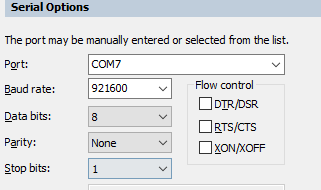
- Ensure your PC's serial terminal software (such as PuTTY, MobaXterm, minicom, SecureCRT, etc.) is configured correctly. Typical settings for RDK boards:
- Baud rate: 921600 (some older models or special cases may use 115200; refer to your board's documentation)
- Data bits: 8
- Stop bits: 1
- Parity: None
- Flow control: None
- COM Port: Make sure you select the correct port as recognized by your PC after connecting the USB-to-serial module.
- Ensure your PC's serial terminal software (such as PuTTY, MobaXterm, minicom, SecureCRT, etc.) is configured correctly. Typical settings for RDK boards:
- USB-to-Serial Driver: Ensure the driver for the USB-to-serial module is correctly installed on your PC.
- Try Other Modules or USB Ports: Rule out hardware issues with the module or USB port.
Network Interface
Q4: The board cannot access the Internet after connecting to the network. How to troubleshoot?
A:
- Check Physical Connection:
- Wired: Ensure the Ethernet cable is properly connected to both the board and the router/switch, and the indicator lights are normal.
- Wireless: Ensure you are connected to the correct Wi-Fi SSID and the password is correct.
- IP Address Configuration:
- DHCP: Usually, the network should be set to obtain an IP address automatically via DHCP. Check if the router's DHCP service is working and if the board has obtained an IP (
ifconfigorip addr). - Static IP: If using a static IP, ensure the IP address, subnet mask, gateway, and DNS server are correctly set and match your LAN environment.
- DHCP: Usually, the network should be set to obtain an IP address automatically via DHCP. Check if the router's DHCP service is working and if the board has obtained an IP (
- Gateway and DNS:
- Ensure the board has the correct gateway address (usually the router's IP).
- Ensure a valid DNS server is configured (try public DNS like
8.8.8.8or114.114.114.114). Useping www.baidu.comto test DNS and Internet connectivity.
- Check Network Status:
- Use
ifconfigorip addrto check interface status and IP configuration. - Use
route -nto view the routing table. - Use
ping <gateway IP>to test connectivity to the gateway.
- Use
- Refer to Official Docs: For detailed steps and troubleshooting, see the "Network Configuration" section (replace with the actual valid doc path).
Q5: Unable to connect to the board via SSH. What could be the reason?
A:
-
Error:
Connection timed out:- Reason: Indicates a network-level issue—your PC cannot find or connect to the board's SSH port (default 22).
- Troubleshooting:
- Ensure the board is powered on and connected to the network (wired or wireless).
- Confirm the board's correct IP address.
- Try
ping <board IP>from your PC. If unreachable, resolve network issues first (check IP config, cables, Wi-Fi, router, firewall, etc.). - Ensure the SSH service (
sshd) is running on the board. Log in via serial and runsudo systemctl status sshorps aux | grep sshd. If not running, start it:sudo systemctl start ssh. - Check if any firewall is blocking port 22.
- Reference: See the SSH Login section (replace with the actual valid doc path).
-
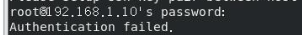
Error:
Authentication failedorPermission denied, please try again.:- Reason: The network connection is established, but the username or password is incorrect.
- Troubleshooting:
- Double-check the username (e.g.,
sunrise,root,hobot, depending on your system image/config). - Double-check the password (case-sensitive).
- Try the default account and password (if not changed).
- Double-check the username (e.g.,
Q6: Wi-Fi connection is unstable or slow. What should I do?
A:
- Signal Strength & Interference:
- The onboard Wi-Fi antenna may have limited performance, especially with metal cases, large heatsinks, or other electronic interference.
- Solution: If your board supports an external Wi-Fi antenna (usually via IPEX or SMA connector), it is strongly recommended to install one for better signal and stability.
- Router Location & Channel:
- Place the board closer to the router and minimize obstacles.
- Try changing the Wi-Fi channel in the router settings to avoid crowded frequencies.
- Driver & Firmware: Ensure the Wi-Fi module driver and firmware are up to date (usually provided with system updates).
- Network Load: Check if other devices on the LAN are using excessive bandwidth.
- 2.4GHz vs 5GHz: If both your board and router support 5GHz Wi-Fi, try connecting to it for less interference and higher speed (note: 5GHz has weaker wall penetration than 2.4GHz).
Q7: No wlan0 (or similar) wireless interface found with ifconfig. How to fix?
A: If ifconfig or ip addr does not show a wireless interface (like wlan0), possible causes and solutions:
- RFKill (Software Block):
- The wireless module may be soft-blocked by RFKill.
- Solution: Run the following to unblock WLAN:
Then check with
sudo rfkill unblock wlan
# or sudo rfkill unblock allifconfig -aorip link show.
- Driver Issue:
- The driver may not be loaded or working. Check kernel logs (
dmesg | grep -i wlanordmesg | grep -i wifi) for errors. - Ensure the correct driver and firmware for your Wi-Fi chip are installed (often provided by packages like
hobot-wifi).
- The driver may not be loaded or working. Check kernel logs (
- Hardware Issue: Rarely, the Wi-Fi module itself may be faulty.
- System Image or Config: Ensure your system image supports the onboard Wi-Fi module and relevant kernel configs are enabled.
USB Interface
Q8: What is the default device node for a USB camera on the board?
A: On Horizon RDK boards (e.g., RDK X3 series), when you connect a standard UVC (USB Video Class) camera, the video device node in Linux is usually not /dev/video0 as on PCs.
- Default device node is usually:
/dev/video8 - It may also be
/dev/video9,/dev/video10, etc., if there are other video devices or multiple USB cameras.
After plugging in the camera, run ls /dev/video* to check the actual device node. When using OpenCV, specify the correct device number (e.g., cv2.VideoCapture(8)).
Q9: No /dev/video8 (or other) device node after plugging in a USB camera. What should I do?
A:
- Check if the camera works: Connect the USB camera to a PC to verify it is recognized and works.
- Check USB connection: Ensure the camera is firmly plugged into the board's USB Host port. Try re-plugging or using another USB Host port if available.
- Avoid Micro USB conflicts (for some boards):
- On some boards (e.g., certain RDK X3 versions), the Micro USB port is used for debugging, ADB, or as a USB Device. If this port is connected to a PC, it may affect other USB Host ports or device enumeration.
- Solution: If the Micro USB is connected, try disconnecting it and then test the USB camera again.
- Check kernel logs: After plugging in the camera, log in via serial or SSH and run
dmesg | tailto view recent kernel messages about USB device detection or driver loading. - USB Power Issue: Some high-power cameras may require more current than the USB port provides. Try using a powered USB hub.
- Driver Compatibility: Most USB cameras follow the UVC standard, and the RDK Linux kernel usually includes the UVC driver. Rare non-standard cameras may have compatibility issues.
Q10: USB gamepad/joystick not working, no /dev/input/js0 device node. How to fix?
A: If no /dev/input/jsX (e.g., js0) device node appears after plugging in a USB gamepad, it's usually due to missing kernel drivers or user-space tools.
- Update the system: Make sure your board's system is up to date, as newer systems may include more drivers.
sudo apt update && sudo apt upgrade - Load kernel driver: Gamepads usually require the
joydevkernel module. Try loading it manually:Then checksudo modprobe joydev
# or sudo modprobe -a joydev/dev/input/forjsXdevices. - Install joystick tools: Install the
joystickpackage for user-space tools.sudo apt install joystick - Test the gamepad: If
/dev/input/js0exists, usejstestto test buttons and axes:Press buttons or move sticks to see output in the terminal.jstest /dev/input/js0 - Check kernel logs: If still not working, check
dmesgafter plugging in the gamepad for errors.
MIPI CSI Interface
Q11: MIPI camera not detected by i2cdetect. What could be the reason?
A:
- Incorrect camera connection:
- FPC cable direction: Ensure the FPC cable is inserted in the correct direction (usually the blue stiffener faces the connector latch, or follow board/camera markings). Incorrect insertion prevents communication.
- Connector lock: Make sure the FPC cable is fully inserted and the connector latches are locked.
- Interface mapping: If the board has multiple MIPI CSI interfaces, ensure the camera is connected to the one specified in software/device tree.
- Reference docs: Check your board's hardware manual or quick start guide for the "MIPI Camera" section (replace with the actual valid doc path) for connection details.
- No hot-plugging: Never plug/unplug MIPI cameras while powered on! Doing so may cause short circuits and damage.
- I2C bus and address: Ensure you use the correct
<bus_number>ini2cdetect -y -r <bus_number>, and know the camera's I2C address. - Camera power/clock: Ensure the camera module is powered and the MIPI clock is present.
- Camera/FPC damage: If all else fails, the camera or FPC cable may be physically damaged.
- Device tree config: Ensure the Linux device tree is correctly configured for the MIPI interface and camera model.
Q12: Running a MIPI camera sample program gives ValueError: invalid literal for int() with base 10: b'open device /dev/lt8618_ioctl failed\ndevice not open\n1080'. How to fix?
A: This error means the program expected a numeric string (e.g., '1080'), but received an error message mixed with a number. In this case, b'open device /dev/lt8618_ioctl failed\ndevice not open\n1080' suggests the program failed to open the display device (/dev/lt8618_ioctl, likely an HDMI control interface), causing the error.
Main causes and solutions:
- Insufficient permissions: Many hardware operations require root privileges. If running as a normal user (e.g.,
sunrise), you may lack permission.- Solution: Run the sample with
sudo:sudo python3 mipi_camera.py
- Solution: Run the sample with
- Display device not ready or misconfigured:
lt8618seems to be an HDMI transmitter chip. If the sample depends on HDMI output and the device is not initialized or is occupied, this error may occur.- Ensure the HDMI monitor is connected and recognized (if required).
- Check kernel logs (
dmesg) for errors aboutlt8618or display initialization.
Display Interface
Q13: What resolutions does the board's HDMI interface support?
A: Supported HDMI resolutions depend on the board model (RDK X3, X5, Ultra, etc.), SoC, and RDK OS version.
- General support: Most RDK boards support common resolutions such as:
- 1920x1080 (1080p) @ 60Hz/50Hz/30Hz
- 1280x720 (720p) @ 60Hz/50Hz
- Lower resolutions like 640x480, 800x600, etc.
- Specific models/versions:
- Newer RDK OS versions (e.g., RDK X3 v2.1.0+) may support more resolutions and refresh rates.
- Higher-end boards (RDK X5, Ultra) may support higher resolutions (e.g., 4K).
- How to check:
- Official docs: The most accurate info is in your board's User Manual or Hardware Specification, in the "HDMI Interface" or display subsystem section (replace with the actual valid doc path).
- In-system (if display connected):
- If the board is running Linux with a display, use
xrandr(in X Window) to see supported modes. - Check kernel logs (
dmesg | grep -i hdmiordmesg | grep -i drm) for detected display modes.
- If the board is running Linux with a display, use
srpi-configtool: Some RDK versions includesrpi-configfor viewing/configuring HDMI output.
If you encounter compatibility issues with a specific monitor, check both resolution and whether the board can correctly parse the monitor's EDID information.