Pinctrl Debugging Guide
X3 Pinctrl uses the pinctrl-single driver from the mainline Linux Kernel code, primarily implementing pinctrl functionality through DTS configuration.
Pin Query
You can find the multiplexing and configuration of IO pins in the datasheets under "PL-2500-3-X3 PIN SW Reg-V1.2.xls".
In "PL-2500-3-X3 PIN SW Reg-V1.2.xls", you can intuitively query the default power-up state, multiplexing, drive strength, pull-up/pull-down configurations, and Schmitt trigger settings for each pin.
Driver Code
drivers/pinctrl/pinctrl-single.c # pinctrl driver source file
include/linux/platform_data/pinctrl-single.h # pinctrl driver header file
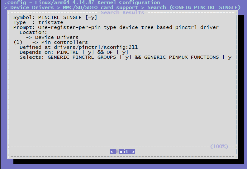
Kernel Configuration
CONFIG_PINCTRL_SINGLE
Pinctrl DTS Configuration
/* arch/arm64/boot/dts/hobot/hobot-pinctrl-xj3.dtsi */
pinctrl: pinctrl@0xA6004000 {
    compatible = "pinctrl-single";
    reg = <0x0 0xA6004000 0x0 0x200>;
    #pinctrl-cells = <1>;
    #gpio-range-cells = <0x3>;
    pinctrl-single,register-width = <32>;
    pinctrl-single,function-mask = <0x3FF>;
    /* pin base, nr pins & gpio function */
    pinctrl-single,gpio-range = <&range 0 120 3>;

    i2c0_func: i2c0_func {
        pinctrl-single,pins = <
            0x020   (MUX_F0 | DRIVE2_09MA | SCHMITT2_DIS | PULL2_UP)
            0x024   (MUX_F0 | DRIVE2_09MA | SCHMITT2_DIS | PULL2_UP)
            >;
    };
    ...
}
Pinctrl Usage
Driver DTS Configuration
Before using the Pinctrl interface, the driver needs to configure the corresponding pinctrl configuration groups in the DTS file. When the driver is probed, the group corresponding to "default" will be configured into the registers. The configuration of other groups needs to be parsed in the code and selected for switching. Taking iar as an example:
/* arch/arm64/boot/dts/hobot/hobot-xj3.dtsi */
iar: iar@0xA4001000 {
    compatible = "hobot,hobot-iar";
    reg = <0 0xA4301000 0 0x400>, <0 0xA4355000 0 0x1000>;
    clocks = <&iar_pix_clk>, <&iar_ipi_clk>, <&sif_mclk>;
    clock-names = "iar_pix_clk","iar_ipi_clk", "sif_mclk";
    interrupt-parent = <&gic>;
    interrupts = <0 69 4>;
    resets = <&rst 0x40 12>;
    pinctrl-names = "bt_func", "rgb_func", "rgb_gpio_func", "bt1120_voltage_func";
    pinctrl-0 = <&btout_func>;
    pinctrl-1 = <&rgb_func>;
    pinctrl-2 = <&rgb_gpio_func>;
    pinctrl-3 = <&bt1120_1_8v_func>;
    disp_panel_reset_pin = <28>;
    reset-names = "iar";
    status = "disabled";
};
The configuration group referenced in the iar pinctrl is defined in arch/arm64/boot/dts/hobot/hobot-pinctrl-xj3.dtsi, and the content is as follows:
btout_func: btout_func {
    pinctrl-single,pins = <
        0x138   (MUX_F0 | DRIVE1_12MA | SCHMITT2_ENA | PULL2_DOWN) /*BT1120_OUT_CLK*/
        0x13c   (MUX_F0 | DRIVE1_12MA | SCHMITT2_DIS | PULL2_DOWN) /*BT1120_OUT_DAT0*/
        0x140   (MUX_F0 | DRIVE1_12MA | SCHMITT2_DIS | PULL2_DOWN)
        0x144   (MUX_F0 | DRIVE1_12MA | SCHMITT2_DIS | PULL2_DOWN)
        0x148   (MUX_F0 | DRIVE1_12MA | SCHMITT2_DIS | PULL2_DOWN)
        0x14c   (MUX_F0 | DRIVE1_12MA | SCHMITT2_DIS | PULL2_DOWN)
        0x150   (MUX_F0 | DRIVE1_12MA | SCHMITT2_DIS | PULL2_DOWN)
        0x154   (MUX_F0 | DRIVE1_12MA | SCHMITT2_DIS | PULL2_DOWN)
        0x158   (MUX_F0 | DRIVE1_12MA | SCHMITT2_DIS | PULL2_DOWN) /*BT1120_OUT_DAT7*/
        0x15c   (MUX_F0 | DRIVE1_12MA | SCHMITT2_DIS | PULL2_DOWN) /*BT1120_OUT_DAT8*/
        0x160   (MUX_F0 | DRIVE1_12MA | SCHMITT2_DIS | PULL2_DOWN)
        0x164   (MUX_F0 | DRIVE1_12MA | SCHMITT2_DIS | PULL2_DOWN)
        0x168   (MUX_F0 | DRIVE1_12MA | SCHMITT2_DIS | PULL2_DOWN)
        0x16c   (MUX_F0 | DRIVE1_12MA | SCHMITT2_DIS | PULL2_DOWN)
        0x170   (MUX_F0 | DRIVE1_12MA | SCHMITT2_DIS | PULL2_DOWN)
        0x174   (MUX_F0 | DRIVE1_12MA | SCHMITT2_DIS | PULL2_DOWN)
        0x178   (MUX_F0 | DRIVE1_12MA | SCHMITT2_DIS | PULL2_DOWN) /*BT1120_OUT_DAT15*/
pinctrl configuration groups combine multiple pin configurations together. Each pin configuration consists of two columns. The first column indicates the offset address of the pin register, which is the pin number multiplied by 4. For example, the pin number of BT1120_OUT_CLK is 78, so the offset address is 78 * 4 = 312, which is converted to hexadecimal as 0x138. The second column indicates the pin's function multiplexing configuration (Pin-mux).
Pin-mux Configuration
Each pin on X3 supports up to 4 functions. When configuring a specific function, customers can refer to the corresponding pinmux value in the register manual. For example, if the mux configuration of pin 78 is 0, which means MUX_F0, the function of the pin is BT1120_OUT_CLK.
/* include/dt-bindings/pinctrl/hobot-xj3.h */
/* MUX functions for pins */
#define MUX_F0          0
#define MUX_F1          1
#define MUX_F2          2
#define MUX_F3          3
Drive Strength Configuration
Each pin on X3 supports configuring the maximum output current. The configuration of drive current is mainly divided into two categories in the pin configuration register. The same register value represents different drive currents on different types of pins. For example, 0 on DRIVE1 represents 3mA, while on DRIVE2 it represents 6mA. Customers can refer to the file arch/arm64/boot/dts/hobot/hobot-pinctrl-xj3.dtsi to determine which category a specific pin belongs to. All pins of the X3 chip are listed in hobot-pinctrl-xj3.dtsi.
/* include/dt-bindings/pinctrl/hobot-xj3.h */
/* drive strength definition */
#define DRIVE_MASK      (4 << 2)
#define DRIVE1_03MA     (0 << 2)
#define DRIVE2_06MA     (0 << 2)
#define DRIVE1_06MA     (1 << 2)
#define DRIVE2_09MA     (1 << 2)
#define DRIVE1_09MA     (2 << 2)
#define DRIVE2_12MA     (2 << 2)
#define DRIVE1_12MA     (3 << 2)
#define DRIVE2_15MA     (3 << 2)
#define DRIVE1_17MA     (4 << 2)
#define DRIVE2_18MA     (4 << 2)
#define DRIVE1_20MA     (5 << 2)
#define DRIVE2_21MA     (5 << 2)
#define DRIVE1_22MA     (6 << 2)
#define DRIVE2_24MA     (6 << 2)
#define DRIVE1_25MA     (7 << 2)
#define DRIVE2_27MA     (7 << 2)
#define DRIVE1_33MA     (8 << 2)
#define DRIVE2_30MA     (8 << 2)
#define DRIVE1_35MA     (9 << 2)
#define DRIVE2_33MA     (9 << 2)
#define DRIVE1_37MA     (10 << 2)
#define DRIVE2_36MA     (10 << 2)
#define DRIVE1_39MA     (11 << 2)
```#define DRIVE2_39MA     (11 << 2)
#define DRIVE1_41MA     (12 << 2)
#define DRIVE2_41MA     (12 << 2)
#define DRIVE1_42_5MA   (13 << 2)
#define DRIVE2_42_5MA   (13 << 2)
#define DRIVE1_44MA     (14 << 2)
#define DRIVE2_44MA     (14 << 2)
#define DRIVE1_45MA     (15 << 2)
#define DRIVE2_45MA     (15 << 2)
Pull-up and Pull-down Configuration
Each pin of X3J3 also supports pull-up and pull-down configuration. Similar to the drive strength configuration, there are two types of configurations for pull-up and pull-down, and the bit positions that need to be manipulated for each type of configuration are different. The specific types of pull-up and pull-down configurations for each pin are listed in hobot-pinctrl-xj3.dtsi. Customers can refer to hobot-pinctrl-xj3.dtsi to find the corresponding configurations.
/* include/dt-bindings/pinctrl/hobot-xj3.h */
/*
 * PULL1 -> bit7(0==pulldown, 1==pullup)
 * bit6(0==pull disable, 1==pull enable)
 *
 * PULL2 -> bit8(0==pullup enable, 1==pullup enable)
 * bit7(0==pulldown diable, 1==pulldown enable)
*/

/* pin states bits */
#define PULL1_MASK      (3 << 6)
#define PULL2_MASK      (3 << 7)
#define PULL1_EN     (1 << 6)
#define PULL1_DIS       (0)
#define PULL2_DIS       (0)
#define PULL1_UP        (PULL1_EN | (1 << 7))
#define PULL2_UP        (1 << 8)
#define PULL1_DOWN      (PULL1_EN | (0 << 7))
#define PULL2_DOWN      (1 << 7)
Schmitt Trigger Configuration
Each pin of X3J3 also supports Schmitt trigger configuration. Similar to the drive strength configuration, there are two types of configurations for Schmitt trigger, and the bit positions that need to be manipulated for each type of configuration are different. The specific types of Schmitt trigger configurations for each pin are listed in hobot-pinctrl-xj3.dtsi. Customers can refer to hobot-pinctrl-xj3.dtsi to find the corresponding configurations.
/* include/dt-bindings/pinctrl/hobot-xj3.h */

/*
* SCHMITT1 -> bit8(0==diable, 1==enable)
*
* SCHMITT2 -> bit9(0==diable, 1==enable)
```/* pin schmitt */
#define SCHMITT1_ENA    (1 << 8)
#define SCHMITT1_DIS    (0 << 8)

#define SCHMITT2_ENA    (1 << 9)
#define SCHMITT2_DIS    (0 << 9)
Driver Calling Example Code
The driver first searches for the corresponding pinctrl state through Pinctrl-names, and then switches to the corresponding state.
static int hobot_xxx_probe(struct platform_device *pdev)
{
    ...
    g_xxx_dev->pinctrl = devm_pinctrl_get(&pdev->dev);
    if (IS_ERR(g_xxx_dev->pinctrl)) {
        dev_warn(&pdev->dev, "pinctrl get none\n");
        g_xxx_dev->pins_xxxx = NULL;
    }
    ...
        /* Lookup state according to pinctrl-names */
        g_xxx_dev->pins_xxxx = pinctrl_lookup_state(g_xxx_dev->pinctrl, "xxx_func");
    if (IS_ERR(g_xxx_dev->pins_xxxx)) {
        dev_info(&pdev->dev, "xxx_func get error %ld\n",
                PTR_ERR(g_xxx_dev->pins_xxxx));
        g_xxx_dev->pins_xxxx = NULL;
    }
    ...
}
int xxxx_pinmux_select(void)
{
    if (!g_xxx_dev->pins_xxxx)
        return -ENODEV;
    /* Switch to the corresponding state */
        return pinctrl_select_state(g_xxx_dev->pinctrl, g_xxx_dev->pins_xxxx);
}
User Space Debugging
If the CONFIG_DEBUG_FS option of Linux Kernel is enabled in the kernel configuration and the debugfs file system is mounted,
mount -t debugfs none /sys/kernel/debug
Then there are some nodes in /sys/kernel/debug/pinctrl/a6004000.pinctrl/ directory in user space where you can view pinctrl information, for example:
cat /sys/kernel/debug/pinctrl/a6004000.pinctrl/pinmux-pins
This command can be used to check which pins are configured as pin groups.