RDK S100 CAN communication
This handbook follows the recorded course slides, including wiring, commands, measured results, and the scope of verification.
Verify CAN from a robot reset to a physical MCU expansion-board loopback.
Two CAN paths, two kinds of evidence
Robot reset shows the application. MCU expansion loopback verifies the S100 physical CAN path.
USB-to-CAN
Run one official reset through the robot SDK.
MCU-CAN
Connect CAN6 transmit to CAN5 receive on the expansion board.
Measured Result
All 12 transmissions match in ID and eight-byte payload.
S100 CAN crosses the MCU expansion path
Acore
Official CAN HAL samples run in Linux user space.
MCU1
Firmware forwards IPC channels to CAN.
Expansion Board
An FPC links the main board and MCU interface board.
Transceivers
CAN5 and CAN6 expose physical differential buses.
From robot application to physical bus
RobotPose offset
USB-to-CANOfficial reset
MCU1running / alive
CAN6→CAN5Three-wire loop
12/12Frame match
S100 resets the robot
The test reuses the same robot_py SDK, existing motor configuration, and default pose without recalibration.
Visible Motion
The waist and multiple joints return from an offset pose.
Official Sequence
Initialize, read, reset, read again, and deinitialize.
Clean Exit
deinit returns not initialized and closes four CAN links.
Keep the two demonstrations distinct
Together they form the lesson evidence, but each uses different hardware.
- Robot reset proves the S100, USB-to-CAN, SDK, and actuator chain can work
- Waist feedback changes by about 43.2 degrees
- One reset is not walking, dancing, or full-joint accuracy acceptance
- The MCU expansion test is not connected to robot motors
- CAN6-to-CAN5 physical loopback proves the expansion-board CAN path
MCU expansion-board CAN loopback
Connect CAN_H, CAN_L, and ground between CAN6 and CAN5, with one 120-ohm termination at each end.
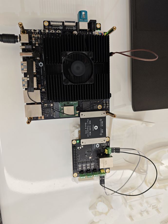
CAN6 H/L/GND → CAN5 H/L/GND | two 120Ω terminations | 1 Mbps
How one frame crosses the full path
can_sendAcore sample
IPC ch6bypass 6
CAN6Physical TX
CAN5Physical RX
IPC ch4can_get output
Run copies of the official examples
The original slash app slash Can directory remains unchanged; code, configuration, and logs stay in the isolated project.
Receiver
Start the receiver before transmitting.
Transmitter
Send an eight-byte classic CAN frame with ID 0x131.
The terminal shows the physical loopback
One recording displays MCU state, transmitted frames, received frames, and final PASS.
Transmit
CAN6 sends twelve frames with ID 0x131.
Receive
CAN5 returns the identical eight-byte payload.
Judge
Report physical CAN PASS only after all 12 frames match.
S100 MCU-CAN measured result
Direction
CAN6 TX → CAN5 RX
Bitrate
1,000,000 bit/s
Frame
ID 0x131 / 8 bytes
Result
12 sent / 12 received / all matched
The test leaves a reproducible state
The expansion-board work stays in an isolated directory and does not rewrite the frozen project or services.
- MCU1 uses the official S100 4.0.5 S100_MCU_DEBUG.elf
- MCU1 reports running and alive during the test
- Official samples are copied into new_project before building
- No canhal_get or canhal_send process remains after testing
- SSH stays enabled; networking and the original project remain unchanged
Check missing frames in order
Channel mapping, termination, and direction must match the current firmware.
Step 1
Confirm MCU1 is running and alive, then verify the official firmware version.
Step 2
Check CAN_H to CAN_H, CAN_L to CAN_L, and ground to ground.
Step 3
Use one 120-ohm termination at each end and configure 1 Mbps.
Step 4
The current firmware is verified with CAN6 transmitting and CAN5 receiving.
RDK S100 CAN verification complete
A robot application and MCU expansion-board loopback demonstrate the S100 CAN development path.
Visible Application
USB-to-CAN drives an official robot reset.
Complete Path
Acore, MCU, FPC, transceivers, and wires are exercised.
Reproducible Result
CAN6 to CAN5 matches 12 of 12 frames.