RDK S100 40-pin GPIO and PWM
This handbook follows the recorded course slides, including wiring, commands, measured results, and the scope of verification.
Verify digital output and hardware dimming with one LED.
Two visible hardware checks
The same LED verifies switching first and continuous brightness control next.
GPIO output
Pin 37 alternates HIGH and LOW so the LED blinks.
PWM dimming
Pin 33 outputs 48 kHz PWM with a changing duty cycle.
Evidence
Wiring photos, camera footage, and sample output support the result.
40-pin wiring limits
S100 digital I/O uses 3.3 V logic. This lesson only uses signal and ground from J24.
- Wire the circuit with power off
- Always place a 330 ohm resistor in series with the LED
- Never short a GPIO output to 3.3 V or ground
- Use BOARD physical pin numbering
- Call GPIO.cleanup() when the program exits
Digital output has two states
HIGH
The output approaches 3.3 V and current flows through the LED.
LOW
The output approaches 0 V and the LED turns off.
Periodic toggle
The sample changes state once per second.
Clean exit
Ctrl+C stops the loop and releases the pin.
GPIO wiring on the board
Connect J24 Pin 37 to 330 ohms, then the LED anode. Return the cathode to Pin 20 ground.
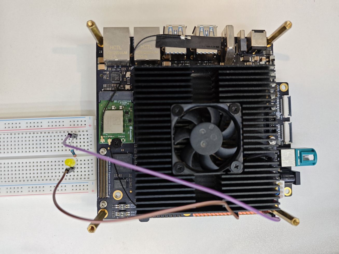
Pin 37 → 330 Ω → LED → Pin 20 GND
Run the official output sample
The board sample uses BOARD numbering and toggles the output continuously.
Command
Press Ctrl+C to stop.
Core logic
The state changes once per second.
GPIO verification flow
Power offCheck Pin 37 and ground
Power onWait for a stable system
RunStart simple_out.py
ObserveLED blinks regularly
ExitCtrl+C and cleanup
Duty cycle controls brightness
Frequency
The sample stays at 48 kHz, far above visible flicker.
Duty cycle
A larger HIGH-time ratio increases average LED brightness.
Hardware channel
S100 40-pin Pins 32 and 33 support LPWM.
Visible result
Brightness rises from 25 percent to 100 percent, then falls.
PWM wiring on the board
Keep the resistor, LED, and ground. Move only the signal wire from Pin 37 to hardware PWM Pin 33.
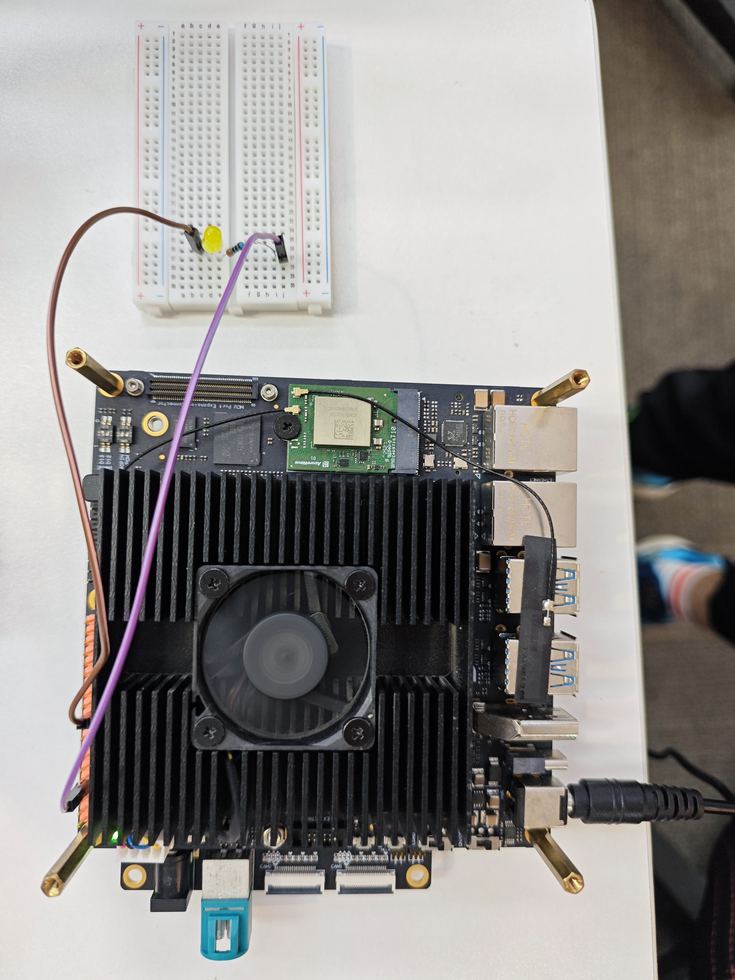
Pin 33 → 330 Ω → LED → Pin 20 GND
Run the hardware PWM sample
simple_pwm.py uses 48 kHz and changes the duty cycle in five-percent steps.
Command
Pin 33 must not be used by another function.
Parameters
Five percent every 0.25 seconds.
PWM verification flow
Power offMove signal to Pin 33
Power onKeep resistor and ground
RunStart simple_pwm.py
ObserveLED fades up and down
ExitStop PWM and cleanup
Two outputs, different jobs
GPIO
Best for on/off control with only HIGH and LOW.
PWM
Best for average-power control such as dimming or speed.
Shared acceptance
Correct wiring, visible behavior, and resource cleanup.
Checks when nothing happens
Inspect the physical circuit before permissions and pin ownership.
Step 1
Power off and check LED polarity, resistor, and ground.
Step 2
Confirm BOARD Pin 37 or Pin 33 in the program.
Step 3
Run with sudo and stop any process using the pin.
Step 4
Restart the test without moving wires while powered.
complete
One LED has verified both GPIO blinking and PWM dimming on the S100 40-pin header.
Repeatable wiring
Pins 37 and 33 serve the two experiments.
Visible behavior
Camera footage preserves blinking and fading.
Next lesson
Continue with UART and I-squared-C communication.