RDK S100 40-pin SPI
This handbook follows the recorded course slides, including wiring, commands, measured results, and the scope of verification.
Verify full-duplex transfer at 12 MHz with one jumper.
SPI0 with the least hardware
The S100 transmits two bytes as master and reads them immediately through the MOSI-to-MISO loop.
One jumper
Connect Pin 19 MOSI directly to Pin 21 MISO.
12 MHz
The official sample sets the bus to 12,000,000 hertz.
Byte acceptance
A continuous 0x55 0xAA return is required.
Four core SPI signals
SCLK
The master clock defines when every data bit is sampled.
MOSI
Master output carries the test bytes.
MISO
Master input receives the looped-back bytes.
CS
Chip select chooses a device; this test opens CS0 through spidev0.0.
SPI0 physical pins on J24
The 40-pin digital interface uses 3.3 V logic, and SPI0 supports master mode only.
- Pin 19: MOSI
- Pin 21: MISO
- Pin 23: SCLK
- Pin 24: CS0
- Pin 26: CS1
- This test connects only Pins 19 and 21
SPI0 loopback wiring
One jumper connects MOSI to MISO. No power, ground, resistor, or external SPI module is needed.
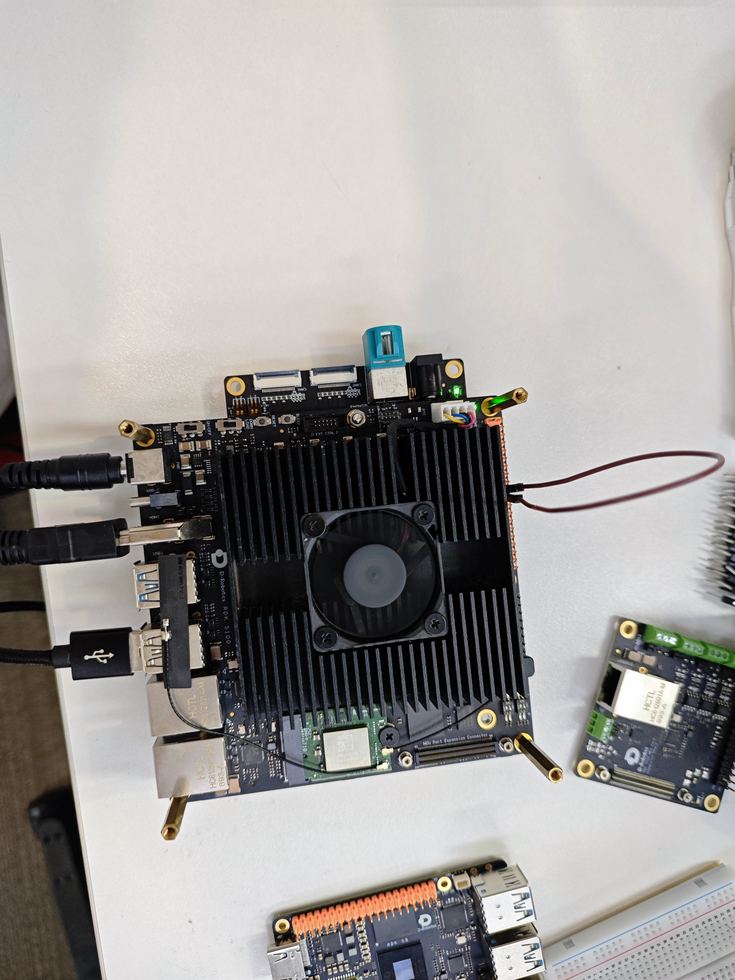
Pin 19 MOSI ↔ Pin 21 MISO
Confirm spidev0.0
The device node connects the Python application to the Linux SPI controller.
List nodes
This run uses /dev/spidev0.0.
Open the controller
bus=0 and chip select=0.
Transmitted data returns directly
Openspidev0.0
TransmitMOSI: 55 AA
LoopPin 19 to Pin 21
ReceiveMISO: 55 AA
CompareExact match PASS
Run the official SPI sample
Enter bus zero and chip select zero. The program transfers one pair of bytes every second.
Command
Enter 0 and 0 when prompted.
Expected output
0x00 0x00 indicates a failed loopback.
Measured SPI0 path
Node/dev/spidev0.0
Format8-bit transfer
Speed12,000,000 Hz
Bytes55 AA repeated
ResultLOOPBACK PASS
Four actions in the sample
SpiDev
Create a Python SPI device object.
open
Select bus zero and chip select zero.
xfer2
Send a list while receiving another list.
close
Release the device handle before exit.
SPI0 acceptance criteria
A running process is not enough. The returned data must be checked.
- /dev/spidev0.0 exists
- Pins 19 and 21 are connected reliably
- The bus runs at 12 MHz
- The program transmits 0x55 0xAA
- The receiver continuously returns 0x55 0xAA
- Ctrl+C closes the device handle
Checks for abnormal output
The loopback is simple, so faults usually come from the node, jumper, or selected parameters.
Node
If spidev0.0 is absent, first confirm that SPI0 is enabled.
Wire
For 0x00 0x00, power off and inspect Pins 19 and 21.
Select
Use bus zero and chip select zero, not another controller.
Access
For permission errors, use sudo and stop stale device users.
Minimal checks for three buses
UART
Short TX and RX to verify asynchronous serial transfer.
I2C
Scan an addressed peripheral, then read and write.
SPI
Short MOSI and MISO for synchronous full-duplex loopback.
complete
S100 SPI0 continuously returns 0x55 0xAA at 12 MHz, completing the minimal loopback check.
Minimal wiring
Only Pins 19 and 21 are connected.
Clear evidence
The terminal output and PASS state are recorded.
Ready to extend
The same bus can later connect a real SPI sensor or display.