7.5.2 MCU Quick Start Guide
Scope
This section provides an overview of the MCU system, aimed at helping readers quickly understand and master the relevant content to facilitate the development of MCU1. Since MCU0 is responsible for booting Acore, MCU1, and power management, it is not recommended for customers to modify this part. The source code is not released by default, and a verified bin file from Dijia is provided. This section only briefly explains potential conflicts with MCU1, aiming to help users avoid resource contention issues between MCU0 and MCU1 during development.
Basic Information
- The MCU compilation toolchain is the GCC toolchain, version gcc-arm-none-eabi-10.3~2021.10.
- The MCU core is ARM R52+, and the ARM R52 technical reference manual can be used as a reference: Official Link
- The operating system running on the MCU is FreeRTOS, version FreeRTOS Kernel V10.0.1.
- The MCU is mainly divided into two parts: MCU0 and MCU1. MCU0 is responsible for booting Acore, MCU1, and power management, and is currently not open-source. MCU1 is responsible for running business functions and is open-source, allowing customers to modify it according to their needs.
MCU Framework
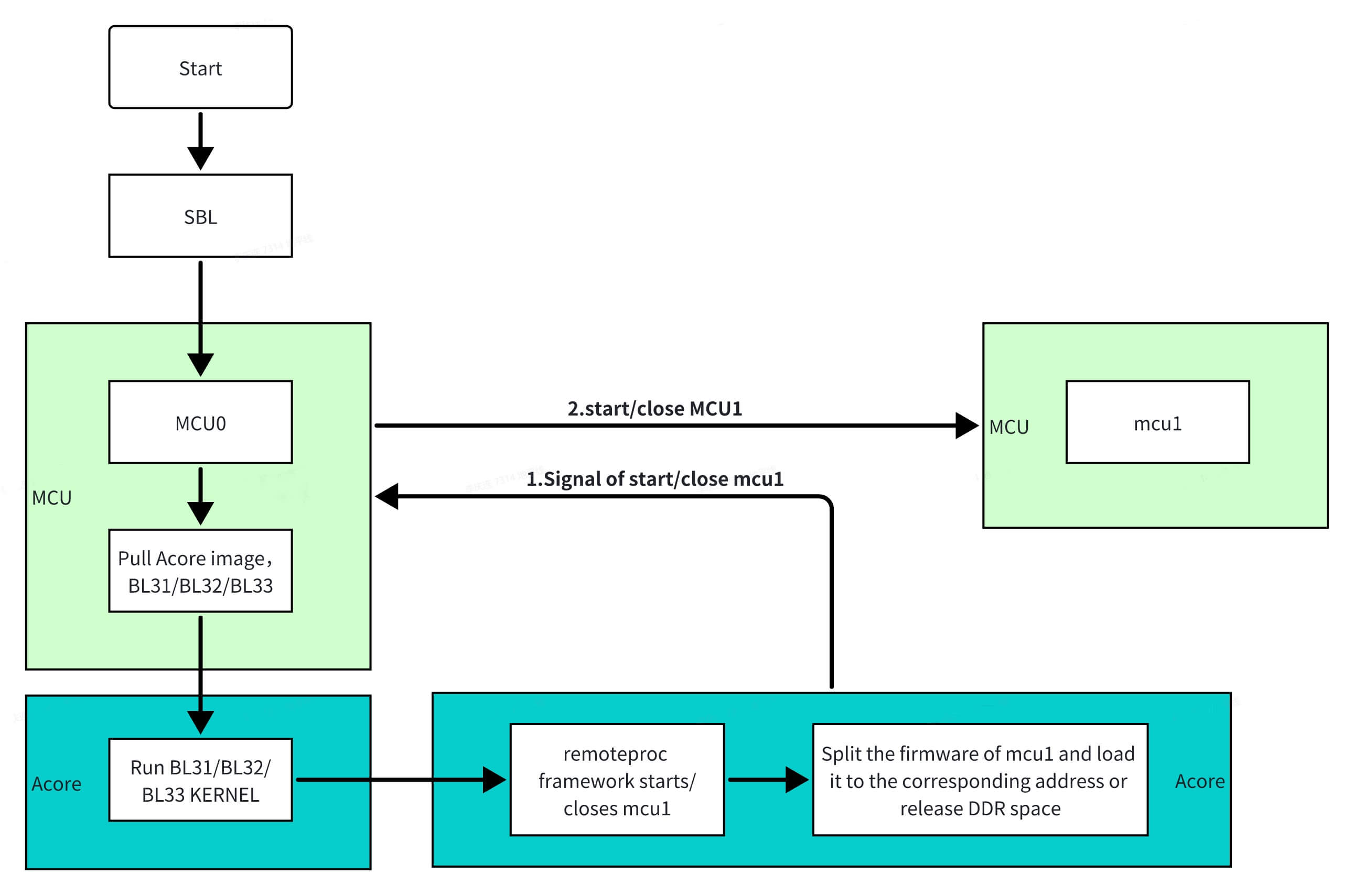
MCU0 is the starting point for booting the board and is of utmost importance. MCU0 is responsible for booting Acore, MCU1, and power management. The Linux operating system running on Acore is a critical platform for customer development, while the FreeRTOS operating system running on MCU1 ensures real-time task execution. MCU1 is implemented using Linux's remoteproc framework. Through Acore's sysfs, notifications are sent to MCU0 to control the startup and shutdown of MCU1. Additionally, during the sleep mode of the RDK-S100, Acore notifies MCU0 to operate MCU1, enabling low-power sleep functionality.
MCU0 is the starting point for booting the board and is of utmost importance. MCU0 is responsible for booting Acore, MCU1, and power management. The Linux operating system running on Acore is a critical platform for customer development, while the FreeRTOS operating system running on MCU1 ensures real-time task execution. MCU1 is implemented using Linux's remoteproc framework. Through Acore's sysfs, notifications are sent to MCU0 to control the startup and shutdown of MCU1. Additionally, during the sleep mode of the RDK-S600, Acore notifies MCU0 to operate MCU1, enabling low-power sleep functionality.
Development Environment
Cross-compilation refers to developing and building software on a host machine and then deploying the built software to run on the development board. Host machines generally have higher performance and more memory than development boards, enabling efficient code building and the installation of more development tools.
Host Compilation Environment Requirements
It is recommended to use the Ubuntu 22.04 operating system to maintain the same system version as the RDK S100, reducing dependency issues caused by version differences.
Install the following software packages on Ubuntu 22.04:
sudo apt-get install -y build-essential make cmake libpcre3 libpcre3-dev bc bison \
                        flex python3-numpy mtd-utils zlib1g-dev debootstrap \
                        libdata-hexdumper-perl libncurses5-dev zip qemu-user-static \
                        curl repo git liblz4-tool apt-cacher-ng libssl-dev checkpolicy autoconf \
                        android-sdk-libsparse-utils mtools parted dosfstools udev rsync python3-pip scons

pip install "scons>=4.0.0"
pip install ecdsa
pip install tqdm
Compiling the MCU System
- Compilation uses python3, and the version of python3 used for RDK S100/S600 development is 3.8.10.
- The MCU1 image comes in two versions: debug and release. The debug version includes debugging information, while the release version does not.
Before compiling MCU1, obtain the MCU code package. Download link:
The first compilation will download the toolchain from the ARM official website and decompress it (about 10 minutes). Poor network conditions may cause the toolchain download to fail or be incomplete. It is recommended to download the compilation toolchain using the following method:
-
Click the Toolchain Download Link to download the compilation toolchain.
-
Move the existing toolchain to /Build/ToolChain/Gcc/. Use the following command to move the toolchain:
mv path_to_toolchain/toolchain-filename path_to_new_code/Build/ToolChain/Gcc/ -
During compilation, if the toolchain is detected, it will not be downloaded from the official website again.
# Compile MCU1 Debug version
cd mcu/Build/FreeRtos_mcu1
python build_freertos.py lite matrix B s100 mcu1 gcc debug

# Compile MCU1 Release version
cd mcu/Build/FreeRtos_mcu1
python build_freertos.py lite matrix B s100 mcu1 gcc release
# Compile MCU1 Debug version
cd mcu/Build/FreeRtos_mcu1
python build_freertos.py lite matrix B s600 gcc mcu1 debug

# Compile MCU1 Release version
cd mcu/Build/FreeRtos_mcu1
python build_freertos.py lite matrix B s600 gcc mcu1 release
Compilation Success Indicator


Compilation Output Directory
output/
├── debug                               # This folder contains the compiled files for the debug version
|    ├── objs                           # i/s/o files generated during compilation
|    └── S100_MCU_SIP_V2.0              # bin/map/elf files generated during compilation
|         ├── custom_compiler_flags.py
|         ├── S100_MCU_DEBUG.elf        # MCU1 boot file
|         ├── S100_MCU_DEBUG.map
|         ├── S100_MCU_SIP_V2.0.bin
├── objs                                # i/s/o files generated during compilation, varies by version
├── release                             # This folder contains the compiled files for the release version
|    ├── objs                           # i/s/o files generated during compilation
|    └── S100_MCU_SIP_V2.0              # bin/map/elf files generated during compilation
output/
├── S600_MCU_DEBUG.map                  # debug link map (in output root directory)
├── S600_MCU_RELEASE.map                # release link map (generated after release build)
├── objs -> output/debug/objs           # symlink pointing to the current build variant objs
├── inc/                                # header files collected during build
├── debug/                              # debug build output
|    ├── objs/                          # i/s/o files generated during compilation
|    └── S600_MCU_Matrix_V2.0/          # elf/bin firmware files
|         ├── S600_MCU_RAW.bin
|         ├── S600_MCU_DEBUG.elf        # MCU1 boot firmware
|         ├── S600_MCU_DEBUG.bin
|         └── S600_MCU_Matrix_V2.0.bin
└── release/                            # release build, similar structure
     ├── objs/
     └── S600_MCU_Matrix_V2.0/
          ├── S600_MCU_RAW.bin
          ├── S600_MCU_RELEASE.elf      # MCU1 boot firmware (release)
          ├── S600_MCU_DEBUG.bin
          └── S600_MCU_Matrix_V2.0.bin
Note:
.mapfiles are generated by the linker in theoutput/root directory for both debug and release builds, namedS600_MCU_DEBUG.mapandS600_MCU_RELEASE.maprespectively. elf/bin files are post-processed into theS600_MCU_Matrix_V2.0/subdirectory underdebug/orrelease/.
MCU1 Startup/Shutdown Process
The startup/shutdown of MCU1 is achieved by Acore passing information to MCU0 via the remoteproc framework, which then starts/shuts down MCU1.
MCU1 Startup Principle and Steps
MCU1 Startup Principle
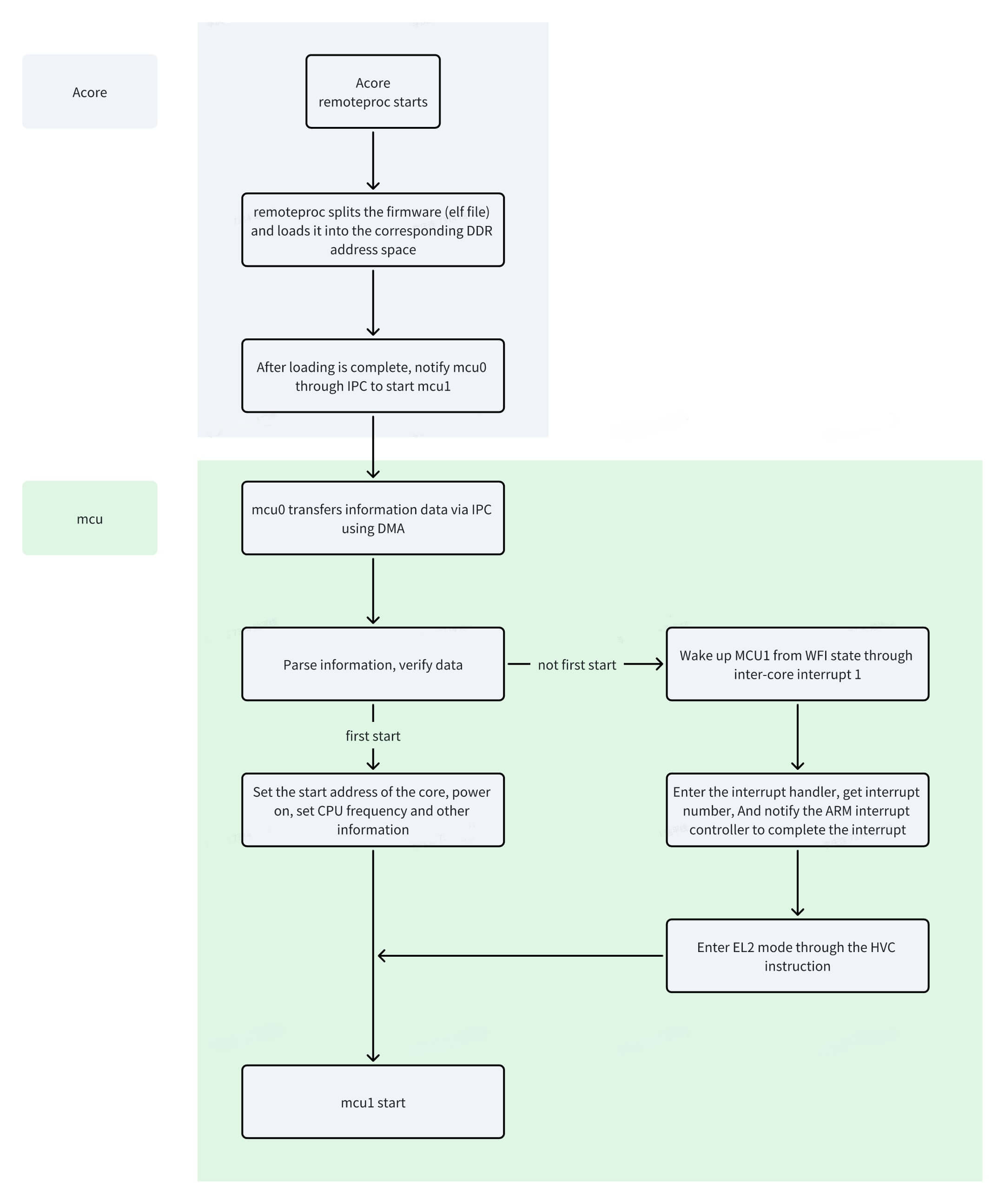
MCU1 Startup Steps
The following startup process uses the debug version as an example. The release version is similar, with fewer log prints.
- After the compilation process described above, compiling the debug version will generate the S100_MCU_DEBUG.elf file in the S100_MCU_SIP_V2.0 folder (similar for the release version). This file is the firmware file for MCU1, so it needs to be pushed to the /lib/firmware directory on the board.
- After the compilation process described above, compiling the debug version will generate the S600_MCU_DEBUG.elf file in the S600_MCU_Matrix_V2.0 folder (similar for the release version). This file is the firmware file for MCU1, so it needs to be pushed to the /lib/firmware directory on the board.
Example: (The screenshots in this and subsequent steps use S100 as an example; S600 is similar)

- Board-side startup process
cd /sys/class/remoteproc/remoteproc_mcu0
echo S100_MCU_DEBUG.elf > firmware
echo start > state
cd /sys/class/remoteproc/remoteproc_mcu0
echo S600_MCU_DEBUG.elf > firmware
echo start > state
Acore-side serial print

MCU-side serial print

MCU1 Shutdown Principle and Steps
MCU1 Shutdown Principle
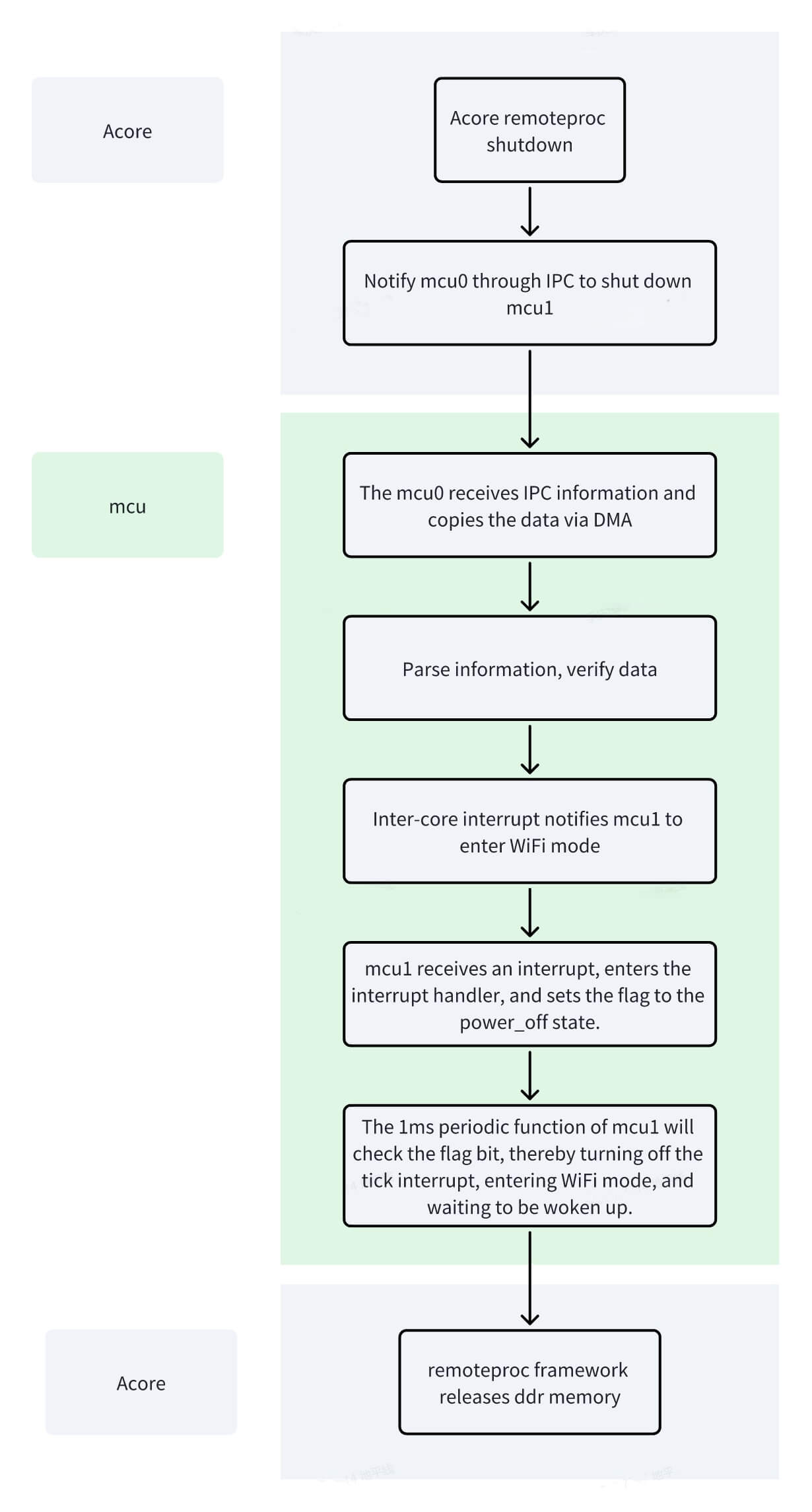
MCU1 Shutdown Steps
The following shutdown process uses the debug version as an example. The release version is similar, with fewer log prints. (The following examples use S100 as an example; S600 is similar)
cd /sys/class/remoteproc/remoteproc_mcu0
echo S100_MCU_DEBUG.elf > firmware
echo stop > state
cd /sys/class/remoteproc/remoteproc_mcu0
echo S600_MCU_DEBUG.elf > firmware
echo stop > state
After successful shutdown, the serial log prints as shown below. Acore-side serial print

MCU-side serial print

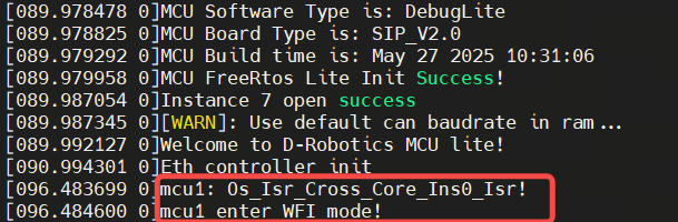
After stopping MCU1, if you need to restart MCU1, you must wait for the system to enter wfi mode before starting MCU1 again, as shown in the figure below. Reason: To avoid the situation where starting MCU1 before the system enters wfi mode reloads the firmware to the MCU SRAM location, overwriting the previous code and causing the system to crash.
MCU0/MCU1 Module Division
The entire MCU system includes modules such as ICU, RTC, IPC, port, and CAN. However, for user development convenience, the functions have been divided as shown in the figure below.
| Module | Module Location |
|---|---|
| ppslcu | MCU0 |
| port | MCU0 |
| uart | MCU0/MCU1 |
| log | MCU0/MCU1 |
| shell_init | MCU0/MCU1 |
| mDma | MCU0/MCU1 |
| I2c | MCU0: i2c6, i2c7 / MCU1: i2c8, i2c9 |
| tca9539 | MCU0 |
| ICU | MCU0 |
| GPT | MCU0 |
| pmic | MCU0 |
| fls_init | MCU0 |
| otaflash | MCU0 |
| ipc | MCU0: instance8 / MCU1: instance0 (other instances not divided, all available) |
| crypto | MCU0 |
| pvt | MCU0 |
| canGW | MCU1 |
| Rtc | MCU0 |
| RTC_pps | MCU0 |
| Eth_Init | MCU1 |
| Scmi | MCU0 |
| Module | Module Location |
|---|---|
| ppslcu | MCU0 |
| port | MCU0 |
| uart | MCU0/MCU1 |
| log | MCU0/MCU1 |
| shell_init | MCU0/MCU1 |
| mDma | MCU0/MCU1 |
| I2c | MCU0/MCU1 |
| tca9539 | MCU0 |
| ICU | MCU0 |
| GPT | MCU0 |
| pmic | MCU0 |
| fls_init | MCU0 |
| otaflash | MCU0 |
| ipc | MCU0: instance8 / MCU1: instance0 |
| crypto | MCU0 |
| pvt | MCU0 |
| Rtc | MCU0 |
| RTC_pps | MCU0 |
| Eth_Init | MCU1 |
| Scmi | MCU0 |
| Can | MCU1: Can1, Can2, Can3, Can4, Can10 |
Debug Functions of MCU on sysfs
The MCU currently supports viewing system status (alive), system uptime (taskcounter), MCU version (mcu_version), SBL version (sbl_version), and other functions on sysfs.
- System status (alive): Indicates the status of MCU0/MCU1, which can be either alive or dead. The MCU alive status updates every 1 second, so there is a 1-second delay when retrieving the status.
- System uptime (taskcounter): Indicates the time elapsed since the MCU started, in seconds.
- MCU version (mcu_version): Displays MCU version information, including whether it is a debug or release version and the compilation time.
- SBL version (sbl_version): Displays SBL version information and compilation time, but can only be viewed under remoteproc_mcu0.
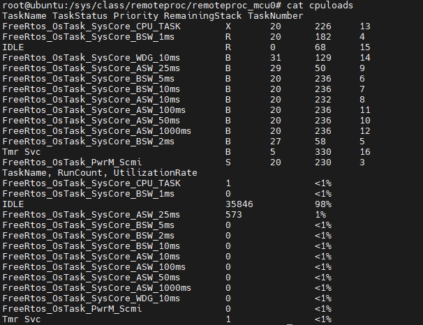
- MCU cpuloads: Provides information such as the task status, priority, remaining stack, execution count (FreeRTOS tick count), and usage rate for each task on MCU0/MCU1, helping users debug. Retrieving cpuloads data requires a 1-second delay because it involves copying a large amount of data to the output buffer under the sysfs file system. Cpuloads can only be retrieved when MCU0/MCU1 are powered on.
- Firmware name (firmware): The firmware name used by MCU0 to start MCU1 under the remoteproc framework. When MCU0 starts MCU1, Linux looks for the corresponding file in the /lib/firmware directory on the board and loads it to the appropriate location.
- Node name (name): For example, mcu0 corresponds to soc:remoteproc_mcu0, and mcu1 corresponds to soc:remoteproc_mcu1.
- Status (state): Refers to the status of the remoteproc subsystem. Starting MCU1 changes the status of the MCU0 remoteproc node to running. When MCU1 is not started, the status is offline.
- Recovery node: Indicates whether coredump register information can be retrieved if the MCU crashes. This feature is enabled by default. For more information, refer to the MCU Ramdump section.
- Uevent node: Indicates the device type, which is DEVTYPE=remoteproc.
- Timesync node: Required for synchronizing the time between master and slave devices. The MCU does not support this feature.
- System status (alive), as shown:

- System uptime (taskcounter), as shown:

- MCU version (mcu_version), as shown:

- SBL version (sbl_version), as shown:

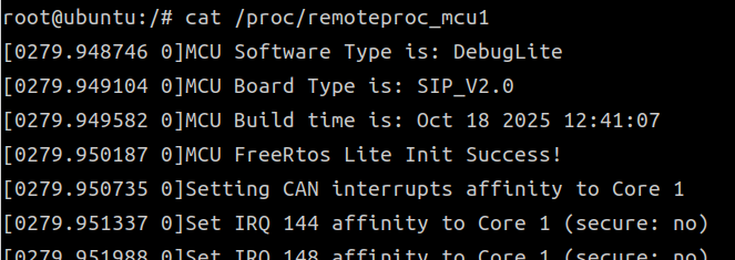
- Retrieving MCU serial log, as shown:
- Retrieving MCU cpuloads, as shown:
MCU Serial Port Usage
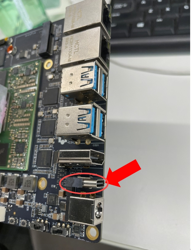
If the RDK-S100 has the following connection method, the MCU serial port and the Acore serial port share one serial port. Check: Device Manager -> Ports -> MCU-COM -> Baud rate 921600.
If the RDK-S600 has the following connection method, the MCU serial port and the Acore serial port share one serial port. Check: Device Manager -> Ports -> MCU-COM -> Baud rate 921600.

MCU0 Flashing Process
Manual Flashing
Non-Empty Board Flashing
- Power on the board, press and hold Enter on the Acore serial port to enter uboot (must keep pressing).
fastboot 0
- Locate the corresponding MCU0 image in the compiled MCU0 image directory /output_sysmcu/ (MCU0 code is only provided in the commercial version). This example uses the S100 MCU0 image.
fastboot oem interface:mtd
/* Compiled S100 MCU0 image: MCU_S100_SIP_V2.0.img */
/* Compiled S600 MCU0 image: MCU_S600_Matrix_V2.0.img*/
fastboot flash MCU_a "xxx/MCU_S100_SIP_V2.0.img"
fastboot flash MCU_b "xxx/MCU_S100_SIP_V2.0.img"
Empty Board Flashing
For empty board flashing, use the Xburn tool to flash a specific area and specify miniboot_flash.
For information on using the XBurn tool to flash specific regions, refer to the Flash specific regions section.
For information on using the XBurn tool to flash specific regions, refer to the Flash specific regions section.
MCU1 Undefined/Abort Exception Handling Principle
Under normal circumstances, after the system enters an Undefined/Abort exception, it proceeds through exception handling and context-saving logic. On RDK S100, MCU1 cannot be hardware power-cycled independently, so the MCU1 remoteproc stop/start flow and the synchronous Undefined/Abort exception handling flow should be understood separately.
Under normal circumstances, when the system encounters an undefined/abort exception, it eventually enters an infinite loop. Only by re-executing the power-on/power-off process can it return to normal operation. Since the RDK-S600 cannot power on/off MCU1 independently, system process modifications are required to achieve the desired outcome.
Path 1: remoteproc software stop/start (daily start/stop)
After Acore executes echo stop > state via sysfs, MCU0 triggers an inter-core interrupt, and MCU1 clears run flags before entering STANDBY or deep sleep. On the next echo start > state, MCU1 starts again through software boot.
On MCU1 of S100, core0 stop/deepsleep handling is mainly in Cross_Core_Ins0 / Cross_Core_Ins2, and core1 stop/deepsleep handling is mainly in Cross_Core_Ins3 / Cross_Core_Ins5. The relevant code is in:
mcu/Target/Target_S100/Target-hobot-lite-freertos-mcu1/target/FreeRtosOsHal/Isr_Hal.cmcu/Target/Target_S100/Target-hobot-lite-freertos-mcu1/target/main.c
Code example:
void Os_Isr_Cross_Core_Ins0_Isr(void)
{
  LogSync("mcu1: %s!\r\n",__func__);
  power_on = 0;
  ClearCrossCoreISR0();
  if (exception_on)
  {
    exception_on = 0;
  }
}

void Os_Isr_Cross_Core_Ins3_Isr(void)
{
  LogSync("mcu1: %s!\r\n",__func__);
  power_on_core1 = 0;
  ClearCrossCoreISR3();
  if (exception_on_core1)
  {
    exception_on_core1 = 0;
  }
}
Path 2: synchronous Undefined/Abort exceptions
In startup.s for S100 MCU1, the EL1 exception vector table entries are call_EL1_Undefined_Handler / call_EL1_Abort_Handler, rather than EL1_Undefined_Handler in main.c.
Undefined exceptions jump directly into Os_SaveCrashDump0 to save a crash dump. Prefetch/Data Abort first call User_Abort_Handler_pre / User_Abort_Handler to record fault information, and then enter Os_SaveCrashDump0.
Code example:
EL1_core_exceptions_table:
    b   EL1_Reset_Handler
    b   call_EL1_Undefined_Handler
    ldr pc, =vPortSVCDispatcher
    b   call_EL1_Prefetch_Handler
    b   call_EL1_Abort_Handler
    b   EL1_DefaultISR
    ldr pc, =vPortInterruptDispatcher
    b   EL1_FIQ_Handler

call_EL1_Undefined_Handler:
    push {r0}
    mov r0, #(0x100*1+18)
    b Os_SaveCrashDump0

call_EL1_Abort_Handler:
    STMFD SP! , {R0-R12,LR}
    ...
    bl User_Abort_Handler
    ...
    b Os_SaveCrashDump0
Specific principle: S600 MCU1 involves two independent paths.
Path 1: remoteproc software stop/start (daily start/stop)
After Acore executes echo stop > state via sysfs, MCU0 triggers inter-core interrupt Ins0. MCU1 clears the run flags and puts core1 into STANDBY or deep sleep. The next echo start > state triggers a software restart of MCU1. Related code is in Target/Target_S600/Target-hobot-lite-freertos-mcu1/target/FreeRtosOsHal/Isr_Hal.c and main.c:
/* Isr_Hal.c */
void Os_Isr_Cross_Core_Ins0_Isr(void)
{
  LogSync("mcu1: %s!\r\n", __func__);
  power_on_core1 = 0;
  power_on = 0;
  ClearCrossCoreISR0();
  if (exception_on)
  {
    exception_on = 0;
  }
}

/* main.c — core1 branch (excerpt) */
while (1) {
    if (0 == power_on_core1) {
        Os_Disable_Can4_DataIsr();
        /* ... disable Can6~Can10 ... */
        if (1 == deep_sleep_core1) {
            LogSync("core1 enter deepsleep...\r\n");
            Mcu1_Enter_Sleep_Core1();
        } else {
            LogSync("core1 enter stop...\r\n");
            STANDBY();
        }
    }
}
Path 2: synchronous Undefined/Abort exceptions
In startup.s, the EL1 exception vector table entries are call_EL1_Undefined_Handler / call_EL1_Abort_Handler, not the EL1_Undefined_Handler in main.c. Synchronous exceptions are handled by User_Undefined_Handler / User_Abort_Handler in HorizonHook.c, which record fault information and then enter Os_SaveCrashDump0 to save the crash dump:
/* HorizonHook.c — Undefined exception (excerpt) */
uint32 User_Undefined_Handler(void *reg)
{
    LogSync("[MCU%u Core%u] Enter Undefined Instruction Handler!!!\r\n",
            (unsigned int)cluster_id, (unsigned int)core_id);
    LogSync("Estimated undefined fault PC: 0x%x\r\n", fault_pc);
    /* ... print instruction and context ... */
    return 1u;
}
Although S600_Exception_Handler, EL1_Undefined_Handler, and EL1_Abort_Handler are defined in main.c, the EL1 exception vector table does not currently jump to these functions. They are not part of the actual execution path for synchronous exceptions described above. This issue has been recorded and is planned for fix in a future MCU code release.
Introduction to the MCU1 main Function
The main function is the key code after system entry. On MCU1, the current flow branches by GetCurrentCoreID() between core0 and core1 initialization. Core0 handles major peripheral init, logging, version info, GIC WAKER, IRQ affinity, and FreeRTOS task setup; core1 handles Can5~Can9 data interrupts, inter-core interrupts, and stop/deepsleep flow.
The following excerpt shows key logic in the current RDK S100 MCU1 main function. Do not remove these initialization steps arbitrarily, or startup, remoteproc stop/start, CAN interrupt handling, or low-power flows may fail.
int main(void)
{
    unsigned long core_id = GetCurrentCoreID();

    if (core_id == 0) {
        /* core0 execution path:
         * Ipc_MainPowerUp, Can2Atcm_Init, PpsIcu_Irq_Init, Uart_Init,
         * Log_Init, Shell_Init, Version_into_AonSram, etc.
         */
        LogSync("MCU FreeRtos Lite Init Success!\r\n");

        /* Configure gicr0/gicr1 WAKER, keep bit3 and bit0 */
        /* ... read/write GIC WAKER registers such as 0x22100014 and 0x22120014 ... */

        FreeRtos_Irq_Init();
        SetCanInterruptAffinity(1);
        SetIPCInterruptAffinity(1);
        SetCrossCoreInterruptAffinity(1);
        FreeRtos_Task_Init();

        for(;;){};
    } else if (core_id == 1) {
        /* core1 execution path:
         * Enable Can5~Can9 data interrupts and Cross_Core_Ins3/4/5.
         */
        __asm__ volatile("cpsie i");
        __asm__ volatile("cpsie f");

        while(1) {
            if(0 == power_on_core1) {
                /* Disable Can5~Can9 data interrupts before stop/deepsleep */
                /* ... Os_Disable_Can5_DataIsr() ~ Os_Disable_Can9_DataIsr() ... */

                if(1 == deep_sleep_core1) {
                    Mcu1_Enter_Sleep_Core1();
                } else {
                    InvalidateCache();
                    STANDBY();
                }
            } else {
                __asm__ volatile("wfe");
            }
        }
    }
}
int main(void)
{
    unsigned long core_id = GetCurrentCoreID(); /* Get the core ID of the current cluster */
    if (core_id == 0) {             /* Core 0 execution logic */
        /* ... Ipc_MainPowerUp, Disable_AonTimer, Can2Atcm_Init, Uart_Init,
              Log_Init, Version_into_AonSram, etc. ... */
        LogSync("MCU1 FreeRtos Lite Init Success!\r\n");

        uint32_t gicr0_waker_addr = 0x22100014; /* Configure gicr0 WAKER, keep bit3 and bit0 */
        /* ... read/write gicr0 WAKER register ... */

        uint32_t gicr1_waker_addr = 0x22120014; /* Configure gicr1 WAKER, keep bit3 and bit0 */
        /* ... read/write gicr1 WAKER register ... */

        FreeRtos_Irq_Init();
        SetCanInterruptAffinity(1);       /* CAN IRQs routed to core1; no per-Can enable on core1 */
        SetIPCInterruptAffinity(1);
        SetCrossCoreInterruptAffinity(1); /* Inter-core IRQs routed to core1 */
        FreeRtos_Task_Init();

        for(;;){};
   } else if (core_id == 1) {         /* Core 1 execution logic */
        Os_Enable_Cross_Core_Ins3_DataIsr();
        __asm__ volatile("cpsie i");
        __asm__ volatile("cpsie f");

        while(1) {
            if(0 == power_on_core1)
            {
                Os_Disable_Can4_DataIsr();
                /* ... disable Can6~Can10 ... */

                if(1 == deep_sleep_core1)
                {
                    Mcu1_Enter_Sleep_Core1(); /* Enter deep sleep */
                }
                else
                {
                    STANDBY();              /* Enter WFI/STANDBY */
                }
            }
        }
        for(;;){};
   }
}
Introduction to MCU Log
The MCU provides basic log output functionality, primarily for debugging and recording runtime status. The current version of the log module supports outputting information via formatted strings, making it easier for developers to quickly locate issues and view variable states during debugging. On the Acore side, log information for MCU0 and MCU1 can be viewed through the /proc/remoteproc_mcu0 and /proc/remoteproc_mcu1 nodes.
Example of retrieving MCU1 serial log information, as shown below:
Currently, the MCU Log supports the following formatted output types:
- %s — String
- %d — Decimal signed integer
- %u — Decimal unsigned integer
- %x — Hexadecimal lowercase format
- %X — Hexadecimal uppercase format
- %c — Single character
Other formatted output types are not supported at this time. Future versions will gradually expand support for more data types and formats to meet richer debugging needs.