7.5.5 UART User Guide
The S100 MCU chip has a total of 3 UARTs, namely Uart4 to Uart6. Among them, Uart4 is used as a debug console (shared by MCU0 and MCU1), DMA is not enabled by default, and the default configuration is as follows:
| Configuration Item | uart4 | uart5 | uart6 |
|---|---|---|---|
| Channel Identifier | Uart_Channel0 | Uart_Channel1 | Uart_Channel2 |
| Baud Rate | 921600 | 921600 | 921600 |
| Parity Bit | None | None | None |
| Stop Bit | 1 bit | 1 bit | 1 bit |
| Data Bit | 8 bits | 8 bits | 8 bits |
Hardware Support
- Maximum number of UARTs available on MCU: 3
- UART FIFO depth: 64 * 8bit, water level: half full
- Supports common baud rates such as 4800, 9600, 38400, 115200, 921600
- Supports 5~8 data bit configuration
- Supports parity configuration
- Supports 1, 1.5, 2 stop bit configuration
- Supports DMA mode. In DMA mode, the transmit and receive buffer addresses provided by the application layer must be 64-byte aligned.
The S600 MCU chip has a total of 4 UARTs, namely Uart8 to Uart11. Among them, Uart8 is used as a debug console (shared by MCU0 and MCU1), DMA is not enabled by default, and the default configuration is as follows:
| Configuration Item | uart8 | uart9 | uart10 | uart11 |
|---|---|---|---|---|
| Channel Identifier | Uart_Channel0 | Uart_Channel1 | Uart_Channel2 | Uart_Channel3 |
| Baud Rate | 921600 | 921600 | 921600 | 921600 |
| Parity Bit | None | None | None | None |
| Stop Bit | 1 bit | 1 bit | 1 bit | 1 bit |
| Data Bit | 8 bits | 8 bits | 8 bits | 8 bits |
Hardware Support
- Maximum number of UARTs available on MCU: 4
- UART FIFO depth: 8byte x 16
- Supports common baud rates such as 4800, 9600, 38400, 115200, 921600
- Supports 5~8 data bit configuration
- Supports parity configuration
- Supports 1, 1.5, 2 stop bit configuration
- Supports DMA mode. In DMA mode, the transmit and receive buffer addresses provided by the application layer must be 64-byte aligned.
Software Architecture
- UART APP: Application layer code for UART.
- UART Interface: Interface layer code for UART, providing standardized UART operation interfaces.
- UART LLD: Low-level driver code for UART, directly operating hardware registers, implementing core functions such as asynchronous/synchronous transmission, interrupt handling, and FIFO management.
- UART PBcfg: PB configuration file for UART, used for peripheral configuration parameters.
- Hardware: UART hardware.
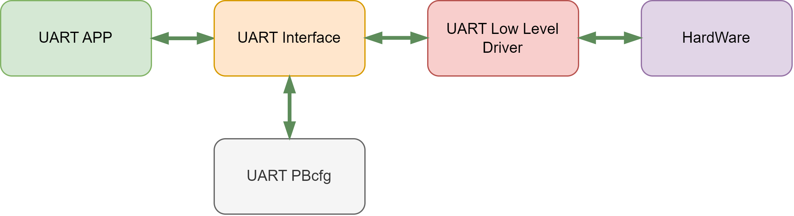
Code Path
McalCdd/Common/Register/inc/Uart_Register.h: Register相关内容McalCdd/Uart/src/Uart.c: Driver codeMcalCdd/Uart/src/Uart_Lld.c: Low-level driver codeMcalCdd/Uart/inc/Uart.h: Driver header fileMcalCdd/Uart/inc/Uart_Lld.h: Low-level driver header fileConfig/McalCdd/gen_xxx/Uart/src/Uart_PBcfg.c: MCU PB configuration fileConfig/McalCdd/gen_xxx/Uart/inc/Uart_PBcfg.h: PB configuration header fileConfig/McalCdd/gen_xxx/Uart/Uart_Board.h: Board-level configuration filesamples/Uart/src/Uart_Test.c: Test code
Application Sample
Usage Example
The S100 development board exposes Uart5 for user development and learning. The PIN is located at the MCU Expansion Header(J22) on the Main Board.
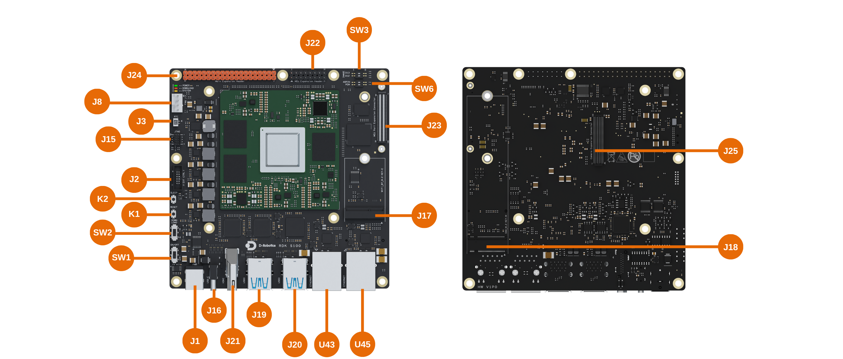
When Uart5 may be used for IPC pass-through, it can conflict with test cases, causing test failures. You can confirm this using the ipcbox_set_mode debug command. If the line for uart shows Enable, it means it is occupied.
D-Robotics:/$ ipcbox_set_mode debug
[0427.611385 0]Module: runcmd, Enable
[0427.611637 0]Module: uart, Enable
[0427.612039 0]Module: spi, Disable
[0427.612440 0]Module: i2c, Disable
If it is confirmed to be occupied, enter the ipcbox_set_mode uart 0 command on the MCU control terminal to release the occupied Uart5:
D-Robotics:/$ ipcbox_set_mode uart 0
[0774.571200 0]uart processing disabled
[0774.690237 0]IpcBox_uart task resources released and terminating
[0775.071611 0]IpcBox_uart task exited properly

D-Robotics:/$ ipcbox_set_mode debug
[0781.748204 0]Module: runcmd, Enable
[0781.748456 0]Module: uart, Disable
[0781.748868 0]Module: spi, Disable
[0781.749270 0]Module: i2c, Disable
uarttest 1Loopback test, note to connect RX pin to TX pin
D-Robotics:/$ uarttest 1
[073.515926 0]Async receive ret: 0
Tx: 0 1 2 3 4 5 6 7 8 9 a b c d e f 10 11 12 13 14 15 16 17 18 19 1a 1b 1c 1d 1e 1f 20 21 22 23 24 25 26 27 28 29 2a 2b 2c 2d 2e 2f 30 31 32 33 34 35 36 37 38                                                                                                                                 39 3a 3b 3c 3d 3e 3f 41 42 43 44 45
Rx: 0 1 2 3 4 5 6 7 8 9 a b c d e f 10 11 12 13 14 15 16 17 18 19 1a 1b 1c 1d 1e 1f 20 21 22 23 24 25 26 27 28 29 2a 2b 2c 2d 2e 2f 30 31 32 33 34 35 36 37 38                                                                                                                                 39 3a 3b 3c 3d 3e 3f 41 42 43 44 45
[073.523782 0]SyncSend & AsyncReceive test pass!
uarttest 2Receive data Here, a serial assistant (configuration: 921600 baud rate 8-N-1) is used to send data to the MCU
D-Robotics:/$ uarttest 2
Rx: 0 1 2 3 4 5 6 7 8 9 a b c d e f 10 11 12 13 14 15 16 17 18 19 1a 1b 1c 1d 1e 1f 20 21 22 23 24 25 26 27 28 29 2a 2b 2c 2d 2e 2f 30 31 32 33 34 35 36 37 38 39 3a 3b 3c 3d 3e 3f 41 42 43 44 45
[0359.598869 0]AsyncSend & ASyncReceive test pass!
uarttest 3Send data
D-Robotics:/$ uarttest 3
Tx: 0 1 2 3 4 5 6 7 8 9 a b c d e f 10 11 12 13 14 15 16 17 18 19 1a 1b 1c 1d 1e 1f 20 21 22 23 24 25 26 27 28 29 2a 2b 2c 2d 2e 2f 30 31 32 33 34 35 36 37 38 39 3a 3b 3c 3d 3e 3f 41 42 43 44 45
-
uarttest 4Get GPS data, internal test case for RDK. -
uarttest 5Set baud rate to 9600
D-Robotics:/$ uarttest 5
[042602.833314 0]Channel 1 Baud: 9600
uarttest 6Set baud rate to 115200
D-Robotics:/$ uarttest 6
[042617.473286 0]Channel 1 Baud: 115200
The S600 development board exposes Uart10 and Uart11 for user development and learning. The PINs are located at the 2x UART(MAIN)/2x UART(MCU)(J18) on the Main Board.
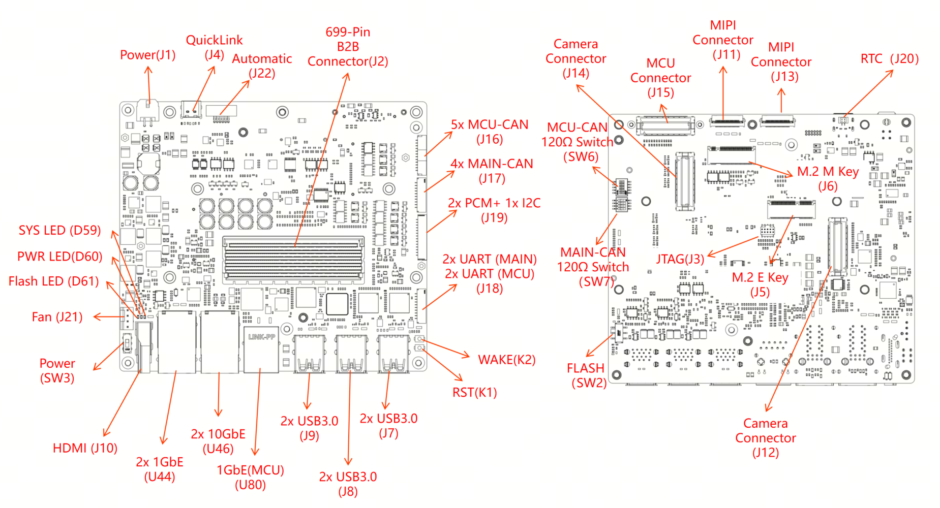
Usage Example
- Syntax format
test_id: Test case ID (required)bus: UART bus number (optional, used by some test cases)baudrate: Baud rate setting (optional, used by some test cases)parity: Parity setting (optional, used by some test cases)stopbit: Stop bit setting (optional, used by some test cases)databits: Data bit setting (optional, used by some test cases)
uarttest <test_id> [bus] [baudrate] [parity] [stopbit] [databits]
uarttest 0 11 921600 0 1 8Configure and initialize the specified UART channel
D-Robotics:/$ uarttest 0 11 921600 0 1 8
[0619.864809 0]g_UartTest updated:
[0619.865186 0]  HwChannel: 3
[0619.865522 0]  BaudRate: 921600
[0619.866698 0]  Parity: 0
[0619.867002 0]  StopBit: 1
[0619.867317 0]  DataBits: 8
[0619.867654 0]Init Uart 3
[0619.867958 0]set data bit success!
[0619.868377 0]set stop bit success!
[0619.868797 0]UART configuration test passed!
uarttest 1Initialize default UART configuration
D-Robotics:/$ uarttest 1
[015229.133055 0]Init Uart 3
[015229.133373 0]set data bit success!
[015229.133816 0]set stop bit success!
[015229.134257 0]UART configuration test passed!
uarttest 2Receive data, test UART receive function Here, a serial assistant (configuration: 921600 baud rate 8-N-1) is used to send data to the MCU
D-Robotics:/$ uarttest 2
Rx: 12 32 34 53 46 0 0 0 0 0 0 0 0 0 0 0 0 0 0 0 0 0 0 0 0 0 0 0 0 0 0 0 0 0 0 0 0 0 0 0 0 0 0 0 0 0 0 0 0 0 0 0 0 0 0 0 0 0 0 0 0 0 0 0 0 0 0 0 0
[0268.494060 0]AsyncSend & ASyncReceive test pass!
uarttest 3Send data, test UART transmit function
D-Robotics:/$ uarttest 3
Tx: 0 1 2 3 4 5 6 7 8 9 a b c d e f 10 11 12 13 14 15 16 17 18 19 1a 1b 1c 1d 1e 1f 20 21 22 23 24 25 26 27 28 29 2a 2b 2c 2d 2e 2f 30 31 32 33 34 35 36 37 38 39 3a 3b 3c 3d 3e 3f 41 42 43 44 45
uarttest 4Loopback test, test both transmit and receive functions
D-Robotics:/$ uarttest 4
Tx: 0 1 2 3 4 5 6 7 8 9 a b c d e f 10 11 12 13 14 15 16 17 18 19 1a 1b 1c 1d 1e 1f 20 21 22 23 24 25 26 27 28 29 2a 2b 2c 2d 2e 2f 30 31 32 33 34 35 36 37 38 39 3a 3b 3c 3d 3e 3f 41 42 43 44 45
Rx: 0 1 2 3 4 5 6 7 8 9 a b c d e f 10 11 12 13 14 15 16 17 18 19 1a 1b 1c 1d 1e 1f 20 21 22 23 24 25 26 27 28 29 2a 2b 2c 2d 2e 2f 30 31 32 33 34 35 36 37 38 39 3a 3b 3c 3d 3e 3f 41 42 43 44 45
[0640.943787 0]SyncSend & AsyncReceive test pass!
Application Interface
void Uart_Init(void)
Description:Subsystem driver initialization function.

Parameters(in)
    None
Parameters(inout)
    None
Parameters(out)
    None
Return value:None
void Uart_Deinit(void)
Description:Subsystem driver deinitialization function.

Parameters(in)
    None
Parameters(inout)
    None
Parameters(out)
    None
Return value:None
Std_ReturnType Uart_BaudSet(uint8 Channel, Uart_BaudrateType Baudrate)
Description:Set baud for an Uart channel.

Parameters(in)
    Channel: Uart Channel
    Baudrate: Desired baud
Parameters(inout)
    None
Parameters(out)
    None
Return value:Std_ReturnType
	E_OK: set success
    E_NOT_OK: set failed
Std_ReturnType Uart_BaudGet(uint8 Channel, uint32* Baudrate)
Description:Get baud for an Uart channel.

Parameters(in)
    Channel: Uart Channel
Parameters(inout)
    None
Parameters(out)
    Baudrate: current baud
Return value:Std_ReturnType
	E_OK: get success
    E_NOT_OK: get failed
Std_ReturnType Uart_SetDatabits(uint8 Channel, uint8 Databits)
Description:Set Databits for an Uart channel.

Parameters(in)
    Channel: Uart Channel
    Databits:Desired Databits
Parameters(inout)
    None
Parameters(out)
    None
Return value:Std_ReturnType
	E_OK: set success
    E_NOT_OK: set failed
Std_ReturnType Uart_SetStopbit(uint8 Channel, uint8 Stopbit)
Description:Set Stopbit for an Uart channel.

Parameters(in)
    Channel: Uart Channel
    Stopbit: Desired Stopbit
Parameters(inout)
    None
Parameters(out)
    None
Return value:Std_ReturnType
	E_OK: set success
    E_NOT_OK: set failed
Std_ReturnType Uart_SetParity(uint8 Channel, Uart_ParityType CurParity)
Description:Set Parity type for an Uart channel.

Parameters(in)
    Channel: Uart Channel
    CurParity:Desired Parity
Parameters(inout)
    None
Parameters(out)
    None
Return value:Std_ReturnType
	E_OK: set success
    E_NOT_OK: set failed
Uart_StatusType Uart_StatusGet(uint8 Channel, uint32* BytesTransfered, Uart_DataDirectionType TransferType)
Description:Gets the status of an Uart channel.

Sync/Async: Synchronous
Parameters(in)
    Channel: Uart Channel
    BytesTransfered: Byte has transfered
    TransferType: Send or Receive
Parameters(inout)
    None
Parameters(out)
    None
Return value:Uart_StatusType
    Uart current state
Std_ReturnType Uart_SyncDataTrans(uint8 Channel, const uint8* Buffer, uint32 BufferSize, uint32 Timeout)
Description:Sends an Uart message blocking.

Sync/Async: Synchronous
Parameters(in)
    Channel: Uart Channel
    Buffer: pointer to Data buffer
    BufferSize: number bytes buffer
    Timeout: Timeout value
Parameters(inout)
    None
Parameters(out)
    None
Return value:Std_ReturnType
    E_OK: command has been accepted
    E_NOT_OK: command has not been accepted
Std_ReturnType Uart_SyncDataReceive(uint8 Channel, const uint8* Buffer, uint32 BufferSize, uint32 Timeout)
Description:Receive an Uart message blocking.

Sync/Async: Synchronous
Parameters(in)
    Channel: Uart Channel
    Buffer: pointer to Data buffer
    ufferSize: number bytes buffer
    Timeout: Timeout value
Parameters(inout)
    None
Parameters(out)
    None
Return value:Std_ReturnType
    E_OK: command has been accepted
    E_NOT_OK: command has not been accepted
Std_ReturnType Uart_AsyncDataTrans(uint8 Channel, const uint8* Buffer, uint32 BufferSize)
Description:Sends an Uart message async.

Sync/Async:Asynchronous
Parameters(in)
    Channel: Uart Channel
    Buffer: pointer to Data buffer
    ufferSize: number bytes buffer
Parameters(inout)
    None
Parameters(out)
    None
Return value:Std_ReturnType
    E_OK: command has been accepted
    E_NOT_OK: command has not been accepted
Std_ReturnType Uart_AsyncDataReceive(uint8 Channel, const uint8* Buffer, uint32 BufferSize)
Description:Receive an Uart message async.

Sync/Async:Asynchronous
Parameters(in)
    Channel: Uart Channel
    Buffer: pointer to Data buffer
    ufferSize: number bytes buffer
Parameters(inout)
    None
Parameters(out)
    None
Return value:Std_ReturnType
    E_OK: command has been accepted
    E_NOT_OK: command has not been accepted
void Uart_GetVersionInfo(Std_VersionInfoType* VersionInfo)
Description:This function Gets the version information of this module

Sync/Async: Synchronous
Parameters(in)
    None
Parameters(inout)
    None
Parameters(out)
    VersionInfo: version information of this module
Return value: None