7.5.10 CAN User Guide
Overview
- Maximum number of usable CAN controllers: 10.
- Maximum CAN transfer rate: 8M. (Limited by transceiver baud rate; the lab has only verified up to 5M baud rate.)
- Number of Blocks partitioned in one controller's RAM:
- CAN0~CAN3: 4 Blocks (variable payload);
- CAN4~CAN9: 4 Blocks (variable payload) + 4 Blocks (fixed payload).
- Maximum number of Mailboxes supported per controller: 128.
- Each controller supports one RxFIFO with depth:
- CAN0~CAN3: 8 * 64 bytes;
- CAN4~CAN9: 32 * 64 bytes.
- TTController is not supported, i.e., TTCAN (a higher-layer protocol based on the CAN bus) is not supported.
- CAN supports multi-packet merge transmission. The merge count and timeout can be configured. Default merge count is 1 and default timeout is 1000us.
- Maximum number of usable CAN controllers: 16.
- Maximum CAN transfer rate: 8M. (Limited by transceiver baud rate; the lab has only verified up to 5M baud rate.)
- Number of Blocks partitioned in one controller's RAM:
- CAN0~CAN3: 4 Blocks (variable payload);
- CAN4~CAN11: 4 Blocks (variable payload) + 4 Blocks (fixed payload).
- CAN12~CAN15: 4 Blocks (variable payload);
- Maximum number of Mailboxes supported per controller: 128.
- Each controller supports one RxFIFO with depth:
- CAN0~CAN3: 8 * 64 bytes;
- CAN4~CAN11: 32 * 64 bytes;
- CAN12~CAN15: 8 * 64 bytes;
- Considering system-level wake-up functionality, the software driver does not support the controller's PretendedNetwork feature.
- TTController is not supported, i.e., TTCAN (a higher-layer protocol based on the CAN bus) is not supported.
- CAN supports multi-core usage. Different CAN controllers can be bound to different cores, but multiple cores cannot use the same CAN controller simultaneously.
Software Architecture
The S100 CAN controllers are located in the MCU domain and are responsible for CAN data transmission and reception. Because perception and other applications run on Acore, some CAN data must be forwarded to Acore through IPC inter-core communication. The architecture ensures transmission reliability. The forwarding mechanism implements data correctness checking, packet loss detection, transmission timeout detection, and similar mechanisms. In addition, it avoids performance issues such as high CPU usage on the MCU side caused by frequent forwarding of small data blocks, which would reduce MCU real-time performance.
The core flow of the S100 CAN forwarding solution is as follows:
- First, the MCU-side CAN2IPC module maps CAN channels to corresponding IPC channels. Then the Acore-side CANHAL module reverse-maps IPC channels to virtual CAN device channels. Finally, users obtain data from virtual CAN devices through APIs provided by CANHAL. CAN2IPC is an MCU-side service; CANHAL is a dynamic library provided to applications on Acore.
- CAN receives data via interrupts. After data is received, the CAN2IPC module is invoked. CAN2IPC packs MCU-side CAN data according to the specified transport protocol and forwards it to Acore through IPC. IPC instance 0 and IPC instance 4 are allocated for CAN. can5-can9 are enabled by default. The correspondence between can5-can9 and IPC is shown in the table below:
| Ipc_ShmCfgInstances | channel | |
|---|---|---|
| can0 | 0 | - |
| can1 | 0 | - |
| can2 | 0 | - |
| can3 | 0 | - |
| can4 | 0 | - |
| can5 | 0 | 4 |
| can6 | 0 | 6 |
| can7 | 4 | 7 |
| can8 | 4 | 2 |
| can9 | 0 | 3 |
- The CANHAL module obtains IPC data from the MCU side, parses it according to the specified transport protocol, and allows application software to obtain raw CAN frames through APIs.
The S600 CAN controllers are located in the MCU domain and are responsible for CAN data transmission and reception. Because perception and other applications run on Acore, some CAN data must be forwarded to Acore through IPC inter-core communication. The architecture ensures transmission reliability. The forwarding mechanism implements data correctness checking, packet loss detection, transmission timeout detection, and similar mechanisms. In addition, it avoids performance issues such as high CPU usage on the MCU side caused by frequent forwarding of small data blocks, which would reduce MCU real-time performance.
The core flow of the S600 CAN forwarding solution is as follows:
- First, the MCU-side CAN2IPC module maps CAN channels to corresponding IPC channels. Then the Acore-side CANHAL module reverse-maps IPC channels to virtual CAN device channels. Finally, users obtain data from virtual CAN devices through APIs provided by CANHAL. CAN2IPC is an MCU-side service; CANHAL is a dynamic library provided to applications on Acore.
- CAN receives data via interrupts. After data is received, the CAN2IPC module is invoked. CAN2IPC packs MCU-side CAN data according to the specified transport protocol and forwards it to Acore through IPC. IPC instance 0 and IPC instance 4 are allocated for CAN. can1-can10 are enabled by default. The correspondence between can1-can10 and IPC is shown in the table below:
| Ipc_ShmCfgInstances | channel | |
|---|---|---|
| can0 | 0 | - |
| can1 | 0 | 1 |
| can2 | 0 | 2 |
| can3 | 0 | 3 |
| can4 | 4 | 4 |
| can5 | 0 | 4 |
| can6 | 4 | 0 |
| can7 | 4 | 1 |
| can8 | 4 | 2 |
| can9 | 4 | 3 |
| can10 | 4 | 5 |
- The CANHAL module obtains IPC data from the MCU side, parses it according to the specified transport protocol, and allows application software to obtain raw CAN frames through APIs.
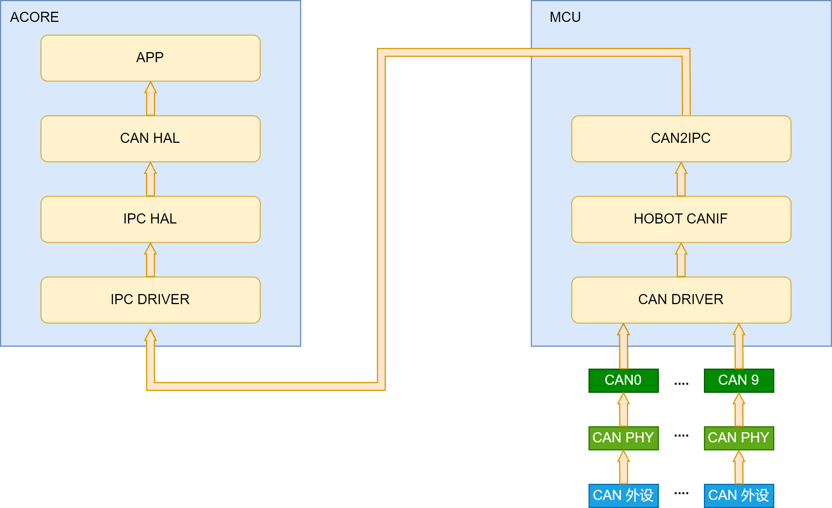
The data flow is shown in the figure above:
- Peripheral data is received by the MCU-domain CAN driver through the CAN PHY and controller devices. The CAN driver reports and buffers data in the hobot CANIF module.
- When the merge count or timeout is reached, the CAN2IPC module is invoked to pack data according to the reliable transport protocol and forward it to Acore through IPC.
- The CANHAL module obtains IPC data from the MCU side and parses it according to the specified transport protocol. Acore applications obtain CAN frames through APIs provided by the CANHAL library.
Solution features:
- Supports data passthrough correctness verification.
- Supports data passthrough packet loss detection.
- Supports transmission timeout detection. When the MCU-side CAN2IPC forwards data, it stamps packets with an MCU-side timestamp. After Acore CANHAL receives data, it reads the Acore timestamp. An alarm is raised if transmission times out. Note: time synchronization must be started in advance to synchronize MCU RTC time with Acore NIC phc0 time.
- Supports parallel transmission on multiple CAN channels. Data from multiple MCU-side CAN controllers can be forwarded to Acore simultaneously. Acore applications read CAN data from different channel numbers through CANHAL.
- Because CANHAL uses IPC for underlying transport, and IPC currently does not support multiple processes or threads reading/writing the same channel, CANHAL does not support this either.
Hardware Connection
-
CAN physical layer topologies are mainly closed-loop bus and open-loop bus networks. One suits high-speed communication and the other suits long-distance communication. The S100 sample defaults to a closed-loop bus network architecture.
-
CAN bus pins are on the S100 MCU expansion board. Five CAN interfaces are brought out. Each connector is a green 3-pin screw terminal. Pin 1 (triangle mark) is GND, the middle pin is CAN_L, and the remaining pin is CAN_H.
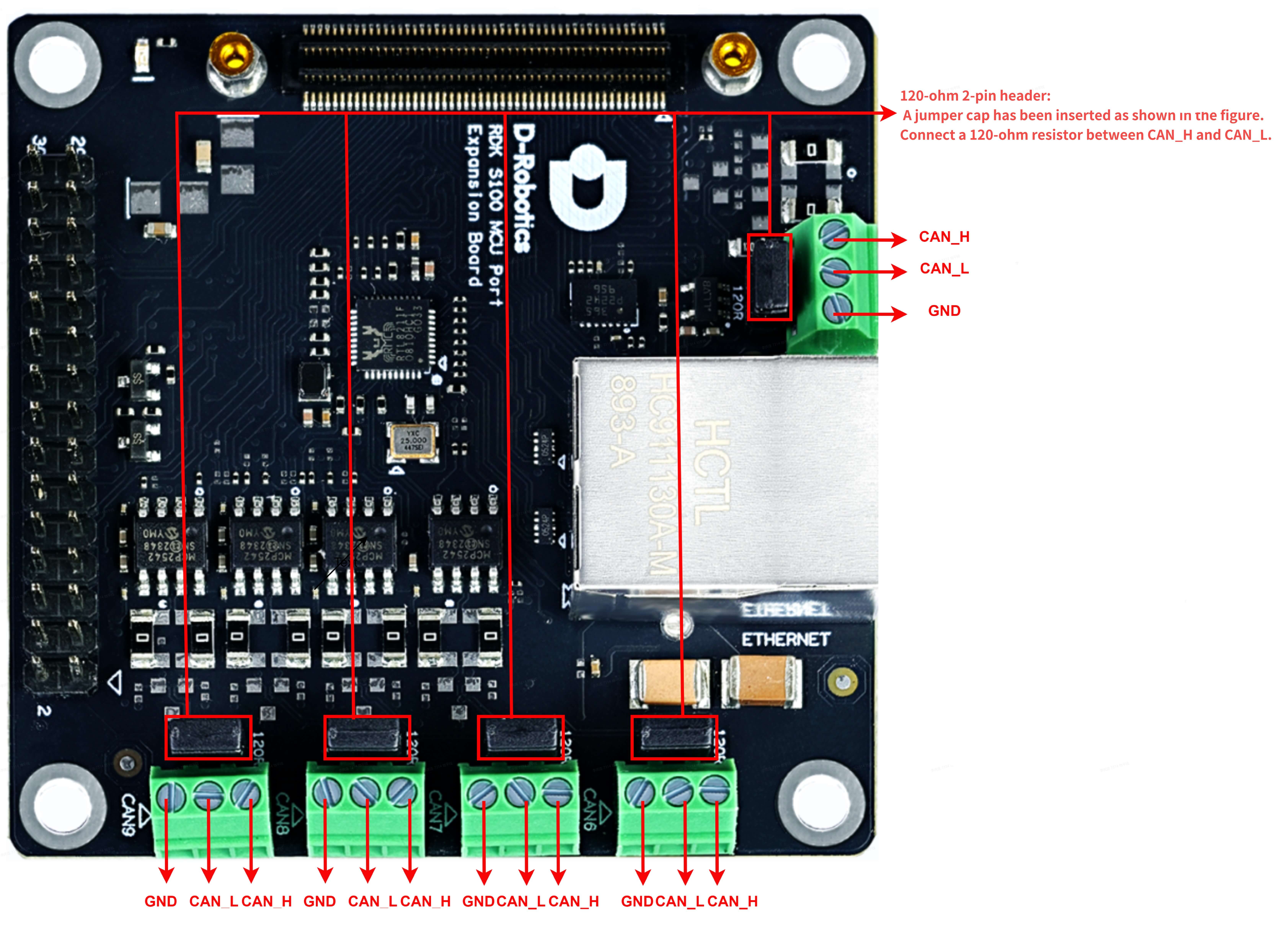
- The MCU daughter board uses a 2-pin jumper to select whether a 120-ohm resistor is connected between CAN_H and CAN_L. When the jumper is inserted, the resistor is connected for terminal matching impedance required by closed-loop networks. When removed, the termination resistor is disconnected for open-loop networks or relay nodes.
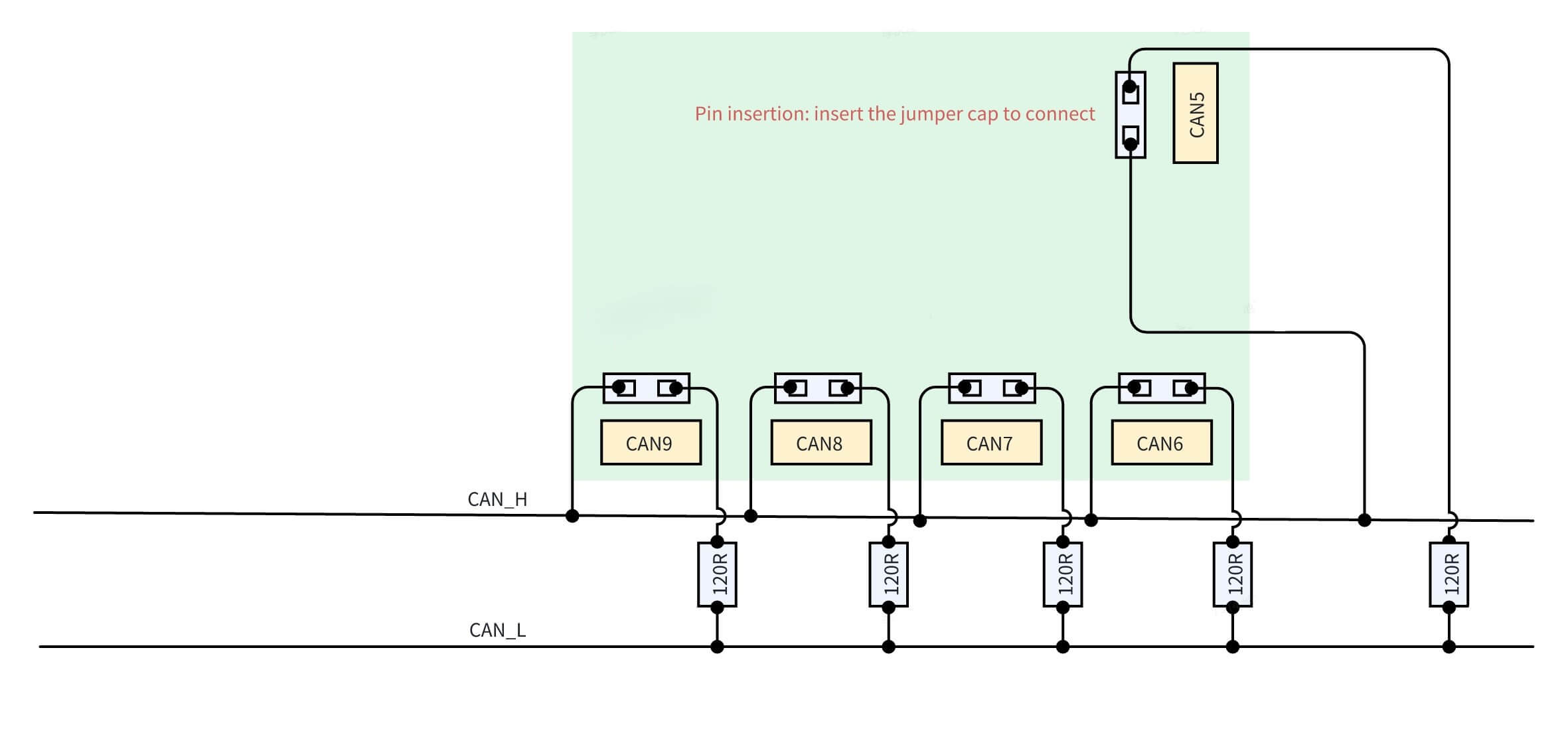
Using two 120-ohm resistors in a CAN closed-loop network is standard. The following uses S100 as an example for correct resistor connection:
In general, open-loop networks do not require 120-ohm resistors, while closed-loop networks require two 120-ohm resistors in total;
- For open-loop networks, ensure CAN_H and CAN_L are connected correctly. Do not insert jumpers on the CAN interfaces in use (no 120-ohm resistors on the network);
- To form a two-node internal closed-loop network with S100 CAN5 and CAN6, ensure CAN_H and CAN_L are connected correctly, and insert jumpers on the pins behind the CAN5 and CAN6 terminals (two 120-ohm resistors on the network);
- To form a multi-node internal closed-loop network with S100 CAN5~CAN9, ensure CAN_H and CAN_L are connected correctly, and insert two jumpers at any two positions. Do not insert more than two jumpers to avoid unpredictable issues;
- To form an external closed-loop network with any controller among S100 CAN5~CAN9 and other CAN devices, besides correct CAN_H and CAN_L connections, insert a jumper behind the RDK CAN controller terminal and connect one 120Ω resistor at another device on the network;
-
CAN physical layer topologies are mainly closed-loop bus and open-loop bus networks. One suits high-speed communication and the other suits long-distance communication. The S600 sample defaults to a closed-loop bus network architecture.
-
S600 brings out 10 CAN interfaces in total. On the MCU expansion board, 5 CAN interfaces are brought out. Each connector is a green 3-pin screw terminal. Pin functions can be found on the back of the MCU daughter board. The base board also brings out 5 CAN interfaces via BP connectors.
-
The MCU daughter board uses DIP switches to select whether a 120-ohm resistor is connected between CAN_H and CAN_L. When the DIP switch is set to ON, the resistor is connected for terminal matching impedance required by closed-loop networks. When set to the numbered position, the resistor is disconnected for open-loop networks or relay nodes.
-
CAN and DIP switches on the MCU expansion board:
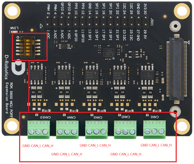
- Correspondence between CAN and DIP switches:
| DIP switch | DIP switch | ||
|---|---|---|---|
| can1 | 1 | can4 | 4 |
| can2 | 2 | can10 | 5 |
| can3 | 3 |
- CAN and DIP switches on the S600 base board:
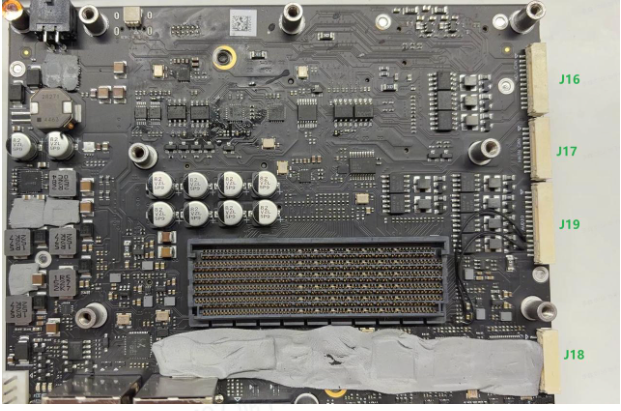
- J16 on the base board is the CAN connector location. Signal names on J16 from top to bottom:
| Signal name |
|---|
| GND |
| CAN5_H |
| CAN5_L |
| CAN6_H |
| CAN6_L |
| GND |
| CAN7_H |
| CAN7_L |
| CAN8_H |
| CAN8_L |
| CAN9_H |
| CAN9_L |
- Base board DIP switches are on the back of the base board

- Correspondence between CAN and DIP switches:
| DIP switch | DIP switch | ||
|---|---|---|---|
| can5 | 1 | can8 | 4 |
| can6 | 2 | can9 | 5 |
| can7 | 3 |
Using two 120-ohm resistors in a CAN closed-loop network is standard. The following uses S600 as an example for correct resistor connection:
- For open-loop networks, ensure CAN_H and CAN_L are connected correctly for the CAN interfaces in use (no 120-ohm resistors on the network);
- To form a two-node internal closed-loop network with S600 CAN1 and CAN2, ensure CAN_H and CAN_L are connected correctly, and set the DIP switches for CAN1 and CAN2 to ON (two 120-ohm resistors on the network);
- To form an external closed-loop network with any controller among S600 CAN1~CAN10 and other CAN devices, besides correct CAN_H and CAN_L connections, set the corresponding RDK CAN controller DIP switch to ON and connect one 120Ω resistor at another device on the network;
CAN Filter Configuration
A maximum of 128 filters can be configured for standard frames and 64 for extended frames. Available filter types:
- ONE_ID_FILTER: specify an ID and configure MASK to ignore certain bits in the ID for filtering,
- RANGE_ID_FILTER: filter by ID range,
- TWO_ID_FILTER: specify two IDs for filtering.
Filter Identification
Filter type is determined by checking the top 2 bits of u32HwFilterCode:
- 0b00: ONE_ID_FILTER
- 0b01: RANGE_ID_FILTER
- 0b10: TWO_ID_FILTER
/**
 * @struct Can_HwFilterType
 * @brief Can Hardware Filter
 * @NO{S01E03C01}
 */
typedef struct Can_HwFilterType
{
    const uint32 u32HwFilterCode;   /**< @brief Specifies (together with the filter mask) the identifiers range that passes the hardware filter. */
    const uint32 u32HwFilterMask;   /**< @brief Describes a mask for hardware-based filtering of CAN identifiers. */
}Can_HwFilterType;
- Configuration example:
- This is the filter configuration for CAN 7 with two filters
- The top 2 bits of the first element of filter 0 are 01, indicating range filtering
- Extended frame and standard frame filtering are independent and do not affect each other
- For all standard frame filters, filters 0 and 1 in the example below are in an OR relationship: if at least one filter element matches, the CAN message is transferred to the enhanced RX FIFO
- Likewise, for all extended frame filters, filters 2 and 3 in the example below are in an OR relationship: if at least one filter element matches, the CAN message is transferred to the enhanced RX FIFO
// Config/McalCdd/gen_s100_sip_B_mcu1/Can/src/Can_PBcfg.c
static const Can_HwFilterType Can_aHwFilter_Object7[4U]=
{
    { /* Standard frame configuration */
        (uint32)0x400007ffU,    // Standard frame: receive messages with ID 0x0~0x7ff
        (uint32)0x00000000U
    },
    { /* Standard frame configuration */
        (uint32)0x400007ffU,   // Standard frame: receive messages with ID 0x600~0x7ff
        (uint32)0x00000600U
    },
    { /* Extended frame configuration */
        (uint32)0x5fffffffU,   // Extended frame: receive messages with ID 0x0~0x1fffffff
        (uint32)0x00000000U
    },
    { /* Extended frame configuration */
        (uint32)0x5fffffffU,   // Extended frame: receive messages with ID 0x600~0x1fffffff
        (uint32)0x00000600U
    }
};
ONE_ID_FILTER (Single ID Filter)
This is the most common filter type. Filtering uses filter code and mask. Pseudocode:
if ((Received_ID & Filter_Mask) == (Filter_Code & Filter_Mask))
    // Accept the message
else
    // Discard the message
Example using standard frame filter 0:
// Config/McalCdd/gen_s100_sip_B_mcu1/Can/src/Can_PBcfg.c
static const Can_HwFilterType Can_aHwFilter_Object7[4U]=
{
    { /* Standard frame configuration */
        (uint32)0x00000400U,  // Only receive messages with id = 0x400&0x7ff = 0x400
        (uint32)0x000007ffU
    },
    {  /* Standard frame configuration */
        (uint32)0x400007ffU,  // Range filter mode; mixed use supported
        (uint32)0x00000600U
    }
    { /* Extended frame configuration */
        (uint32)0x5fffffffU,   // Extended frame: receive messages with ID 0x0~0x1fffffff
        (uint32)0x00000000U
    },
    { /* Extended frame configuration */
        (uint32)0x5fffffffU,   // Extended frame: receive messages with ID 0x600~0x1fffffff
        (uint32)0x00000600U
    }
};
RANGE_ID_FILTER (Range Filter)
In this mode, range filtering logic is used:
if (id1 <= Received_ID <= id2)
    // Accept the message
else
    // Discard the message
This is also the default filtering mode on S100 MCU and the most commonly used. Example code:
// Config/McalCdd/gen_s100_sip_B_mcu1/Can/src/Can_PBcfg.c
static const Can_HwFilterType Can_aHwFilter_Object7[4U]=
{
    { /* Standard frame configuration */
        (uint32)0x00000400U,  // Only receive messages with id = 0x400&0x7ff = 0x400
        (uint32)0x000007ffU
    },
    {  /* Standard frame configuration */
        (uint32)0x400007ffU,  // Range filter mode; mixed use supported
        (uint32)0x00000600U
    }
    { /* Extended frame configuration */
        (uint32)0x5fffffffU,   // Extended frame: receive messages with ID 0x0~0x1fffffff
        (uint32)0x00000000U
    },
    { /* Extended frame configuration */
        (uint32)0x5fffffffU,   // Extended frame: receive messages with ID 0x600~0x1fffffff
        (uint32)0x00000600U
    }
};
TWO_ID_FILTER (Dual ID Filter)
This type allows matching two independent IDs:
- id1: first matching ID
- id2: second matching ID
if (Received_ID == id1 || Received_ID == id2)
    // Accept the message
else
    // Discard the message
Example using standard frame filter 0:
// Config/McalCdd/gen_s100_sip_B_mcu1/Can/src/Can_PBcfg.c
static const Can_HwFilterType Can_aHwFilter_Object7[4U]=
{
    { /* Standard frame configuration */
        (uint32)0x80000404U,// Only receive messages with id 404
        (uint32)0x00000303U // Only receive messages with id 303
    },
    { /* Standard frame configuration */
        (uint32)0x400007ffU,  // Range filter mode; mixed use supported
        (uint32)0x00000600U
    }
    { /* Extended frame configuration */
        (uint32)0x5fffffffU,   // Extended frame: receive messages with ID 0x0~0x1fffffff
        (uint32)0x00000000U
    },
    { /* Extended frame configuration */
        (uint32)0x5fffffffU,   // Extended frame: receive messages with ID 0x600~0x1fffffff
        (uint32)0x00000600U
    }
};
- RDK S100 hardware and software support transmitting and receiving extended and standard frames without configuration changes
- RDK S100 hardware and software support separate filtering for extended and standard frames
- Pay attention to ID length configuration. Values exceeding the specified length are truncated. Extended frame ID length is up to 29 bits (maximum 0x1FFFFFFF); standard frame ID length is up to 11 bits (maximum 0x7FF)
- RDK S600 software does not currently support extended frames
Baud Rate Configuration
CAN nominal bit timing (Nominal bit timing) is divided into four segments:
- Sync segment (sync_seg): used for clock synchronization between nodes. All nodes detect signal edges in this segment. Length is fixed at 1 time quantum (TQ)
- Propagation segment (prop_seg): compensates for signal propagation delay on the physical line. Length is adjustable to ensure transmission time on the physical medium
- Phase buffer segment 1 (phase_seg1): adjusts phase error to ensure accurate sampling points; can be extended for resynchronization
- Phase buffer segment 2 (phase_seg2): also adjusts phase error but can be shortened The sum of these segments determines total CAN bit time. Adjusting segment lengths configures different baud rates. Other important concepts:
- Synchronization Jump Width (SJW): maximum time allowed to adjust phase buffer segments during hard sync and resync to compensate for clock deviation between nodes and align sampling points.
- Transceiver Delay Compensation Offset: supported only in CAN FD; compensates for fixed physical-layer timing offset from transceiver loop delay and signal propagation time during high-speed data segment transmission in CAN FD mode
- Sample point: precise moment within a bit time when the CAN controller samples bus level to determine bit logic value (dominant 0 or recessive 1)
Value Range and Formula Calculation
- Sample point calculation: (sync_seg + prop_seg + phase_seg1) / (sync_seg + prop_seg + phase_seg1 + phase_seg2) × 100%
- Sync segment is fixed at one TQ
- prop_seg + phase_seg1 > phase_seg2
- SJW ≤ min(Phase_Seg1, Phase_Seg2)
- When configuring 5M baud rate and above, compensation parameters must be configured. Formula:
- TDC offset = (PropSeg + Seg1 + 1) * Fd Prescaler
Example: Configure 1M Arbitration Segment and 5M Data Segment
1. Basic Parameter Confirmation
- CAN clock frequency (CAN_CLK): 40 MHz
- Target baud rate (Bit Rate): 5 Mbps
- Prescaler: 1 (no division)
- Total TQ per bit time: TQ = CAN_CLK/(Bit Rate×Prescaler)=40MHz/5Mbps×1=8TQ
- Time quantum: Tq time = 1 / (40M / prescaler) = 1/40M = 25ns
2. Time Quantum (TQ) Allocation
Sync_Seg (fixed segment): 1 TQ (sync segment cannot be modified)
Remaining TQ allocation: Prop_Seg+Phase_Seg1+Phase_Seg2=8−1=7TQ
Here Prop_Seg=1, Phase_Seg1=4, Phase_Seg2=2, so sample point = (Sync_Seg+Prop_Seg+Phase_Seg1)/Total TQ x 100% = (1+4+1)/8 x 100%= 75%
3. Transceiver Delay Compensation Offset
Offset=(Prop_Seg+Phase_Seg1+1)×Prescaler = (1+4+1)×1=6TQ
SJW (Synchronization Jump Width) setting:
SJW must satisfy: SJW≤min(Phase_Seg1,Phase_Seg2)=min(4,2)=2
Therefore, configure SJW = 2 TQ.
4. Final Configuration Parameters
Using the same method, parameters for 1M can be calculated. Because some register values are auto-incremented when read, the value written should be decremented by one. See the table below.
- 5M 75% data segment configuration
| Parameter name | Value (TQ or time) | Value to write to register |
|---|---|---|
| Sync_Seg | 1 TQ | Not written; fixed at 1 |
| Prop_Seg | 1 TQ | 1 |
| Phase_Seg1 | 4 TQ | 3 |
| Phase_Seg2 | 2 TQ | 1 |
| Prescaler | 1 | 0 |
| SJW | 2 TQ | 1 |
| Delay compensation offset | 6 TQ | 6 |
- 1M 80% arbitration segment configuration
| Parameter name | Value (TQ or time) | Value to write to register |
|---|---|---|
| Sync_Seg | 1 TQ | Not written; fixed at 1 |
| Prop_Seg | 7 TQ | 6 |
| Phase_Seg1 | 8 TQ | 7 |
| Phase_Seg2 | 4 TQ | 3 |
| Prescaler | 2 | 1 |
| SJW | 2 TQ | 1 |
5. 8M configuration is special compared to 5M and uses 60% sampling
| Parameter name | Value (TQ or time) | Value to write to register |
|---|---|---|
| Sync_Seg | 1 TQ | Not written; fixed at 1 |
| Prop_Seg | 1 TQ | 1 |
| Phase_Seg1 | 1 TQ | 0 |
| Phase_Seg2 | 2 TQ | 1 |
| Prescaler | 1 | 0 |
| SJW | 1 TQ | 0 |
| Delay compensation offset | 3 TQ | 3 |
6. Update results in the configuration file
Configuration file path:
${mcu_sdk}/Config/McalCdd/gen_s100_sip_B_mcu1/Can/src/Can_PBcfg.c
There are two important baud-rate-related structures in the configuration file. CAN5 is used as an example:
- Can_aControllerConfig: configures CAN controllers. Each controller has a corresponding entry
static const Can_ControllerConfigType Can_aControllerConfig[CAN_CONTROLLER_CONFIG_COUNT]=
{
    ...
 {
        /* Controller ID configured */
        (uint8)5U,
        /* Hw controller Offset */
        (uint8)5U,
        /* Base Address */
        FLEXCAN_5_BASE,
        /* Activation or not */
        (boolean)TRUE,
        /* Bus Off uses polling or not */
        (boolean)TRUE,
        /* Global mask of Legacy FIFO (not used) */
        (uint32)0xFFFFFFFFU,
        /* Acceptance Mode of Legacy FIFO (not used)*/
        CAN_LEGACY_FIFO_FORMAT_A,
        /* Legacy FIFO Warning Notification */
        NULL_PTR,
        /* Legacy FIFO Overflow Notification */
        NULL_PTR,
        /* Enhanced FIFO Overflow Notification */
        NULL_PTR,
        /* Error interrupt enable or not */
        (boolean)TRUE,
        /* Can Error Notification */
        Can_ErrorNotif,
        /* CanFd Error Notification */
        CanFd_ErrorNotif,
        /* Default Baudrate ID, 4--1M+5M 5--1M+8M */
        (uint16)4U,
         /* Baudrate config Count*/
        (uint16)6U,
        /* Pointer to baudrate config Structure */
        Can_aBaudrateConfig_Ctrl5,
        /* Pointer to LLD structure to IP config */
        &Flexcan_aCtrlConfigPB[5U],
        /* HwObject count */
        (uint8)9U,
        /* Point to group of HwObject that referenced to the current Controller */
        Can_apHwObject_Ctrl5
    },
    ...
}
- Can_aBaudrateConfig_Ctrl5: defines baud rate configuration for a specific controller. This is a large array; parameters generated above are written here
static const Can_BaudrateConfigType Can_aBaudrateConfig_Ctrl5[6U]=
{
    {
        /*Enhance CBT support */
        (boolean)TRUE,
        /* Tx Bit Rate Switch or not */
        (boolean)TRUE,
        /* CanFd support */
        (boolean)TRUE,
        /* Nominal bit rate */ // Arbitration segment configuration
        {
            (uint8)6U, // prop_seg
            (uint8)7U, // phase_seg1
            (uint8)3U, // phase_seg2
            (uint16)3U, // Prescaler
            (uint8)1U // SJW
        },
        /* Data bit rate */ // Data segment configuration
        {
            (uint8)3U,
            (uint8)3U,
            (uint8)1U,
            (uint16)3U,
            (uint8)1U
        },

        /* Tx Arbitration Start delay */
        (uint8)12U, // Transceiver Delay Compensation Offset
        /* Tranceiver Delay Disable */
        (boolean)FALSE,
        (uint8)0U
    },
    ...
RDK S100 configures 6 parameter sets by default. Users can select baud rate by modifying u16DefaultBaudrateID in Can_aControllerConfig. Index-to-baud-rate mapping:
| u16DefaultBaudrateID | Arbitration segment | Data segment |
|---|---|---|
| 0 | 500K | 1M |
| 1 | 500K | 2M |
| 2 | 1M | 2M |
| 3 | 1M | 5M (short distance: <50m) |
| 4 | 1M | 5M (long distance: >50m) |
| 5 | 1M | 8M |
Multi-Frame Merge Configuration
The CAN driver supports multi-packet merge reception. When the CAN driver receives a threshold number of packets, they are merged and transmitted from MCU to Acore through IPC. This reduces IPC transmission frequency and improves efficiency. Two configurable parameters are provided: merge count and timeout.
- Merge count: number of packets received before one IPC transmission. Default is 1.
- Timeout: if the threshold count is not reached within the timeout period, a forced transmission is performed. Default is 1000us.
Configuration Method
Configure via MCU serial console as follows:
D-Robotics:/$ Can
Can_Set_Merge_Time    CMD   --------  Set the CAN packet merge timeout in ...
Can_Set_Merge_Num     CMD   --------  Set the number of CAN packages to me...

D-Robotics:/$ Can_Set_Merge_Num 8   // Set merge count to 8

D-Robotics:/$ Can_Set_Merge_Time 100  // Set timeout to 100us
Acore also supports multi-packet merge transmission. Only related data structures are introduced below. Use test cases in Application Sample for modification and verification.
#define CAN_FRAME_NUM (1)   // Number of merged packets on Acore side
struct pack_info pack = { 0 };
pack.data_num = CAN_FRAME_NUM;
Application Sample
Usage Guide
MCU1 must be started before running samples. See MCU1 Startup Steps for the startup procedure.
For Acore CANHAL usage, refer to the sample source directory: source/hobot-io-samples/debian/app/Can. On S100 you can compile and run directly under /app/Can.
Multi-channel passthrough example directory structure:
$ tree /app/Can/can_multi_ch
.
├── Makefile // Main build script
├── config  // Configuration directory
│   ├── channels.json // Channel mapping configuration
│   ├── ipcf_channel.json // IPCF channel mapping configuration
│   └── nodes.json // Virtual CAN device mapping configuration
├── main.cpp // Main program
├── readme.md // Readme
├── can_multich_log.h // Log header
└── run.sh // Run script
JSON configuration mainly includes three files: nodes.json, ipcf_channel.json, and channels.json. To support multiple processes, each process looks for these three files under the config directory in the current path.
nodes.json creates virtual CAN device nodes for CANHAL API access. Key options:
channel_idspecifies which node inipcf_channel.jsonthis virtual CAN device reads data from.targetis the virtual CAN device node name. CANHAL API accesses the specified node through this name.enableindicates whether the node is enabled.
{
  "nodes" : [
    {
      "id" : 0,
      "enable" : true,
      "mode_comment" : "value_table: R, W, RW",
      "mode" : "RW",
      "target" : "can6_ins0ch6",
      "clk_source" : "/dev/hrtc0",
      "io_channel" : {
        "device_type_comment" : "value_table: can, eth, ipcf, spi",
        "device_type" : "ipcf",
        "channel_id" : 0
      },
      "raw_protocol" : "built_1.0"
    },
    .....
    {
      "id" : 4,
      "enable" : true,
      "mode_comment" : "value_table: R, W, RW",
      "mode" : "RW",
      "target" : "can5_ins0ch4",
      "clk_source" : "/dev/hrtc0",
      "io_channel" : {
        "device_type_comment" : "value_table: can, eth, ipcf, spi",
        "device_type" : "ipcf",
        "channel_id" : 4
      },
      "raw_protocol" : "built_1.0"
    }
  ]
}
ipcf_channel.json maps IPC nodes used in nodes.json to specific instance and channel.
{
  "enable" : true,
  "libipcf_path" : "/usr/hobot/lib/libhbipcfhal.so.1",
  "channels" : [
    {
      "id" : 0,
      "channel" : {
        "name" : "can6_ins0ch6",
        "instance": 0,
        "channel": 6,
        "fifo_size": 64000,
        "fifo_type": 0,
        "pkg_size_max": 4096,
        "dev_path":"/dev/ipcdrv",
        "dev_name":"ipcdrv",
        "recv_timeout" : 4000
      }
    },
    ......
    {
      "id" : 4,
      "channel" : {
        "name" : "can5_ins0ch4",
        "instance": 0,
        "channel": 4,
        "fifo_size": 64000,
        "fifo_type": 0,
        "pkg_size_max": 4096,
        "dev_path":"/dev/ipcdrv",
        "dev_name":"ipcdrv",
        "recv_timeout" : 4000
      }
    }
  ]
}
channels.json specifies the IPC configuration file. Users generally do not need to change it.
{
  "io_channels" : {
   "ipcf" : "./config/ipcf_channel.json"
 }
}
Acore cannot operate CAN peripherals directly. Data must be relayed through the IPC module. For peripheral channel mapping, see the IPC usage section in MCU IPC User Guide.
Pseudocode for Acore applications obtaining MCU-side CAN frames through CANHAL:
void send_frame_data(void *arg)
{
... do
{
ret = canSendMsgFrame(test_params->target, &frame[0], &pack);
if (ret > 0) { /* Send success */
send_count++;
PRINT_DEBUG("Send length %d\n", ret);
break;
} else if (ret == -CAN_TRY_AGAIN && /* Retry due to insufficient IPC or other resources */
retry++ < MAX_RETRY) {
usleep(2);
continue;
} else { /* Send failed */
PRINT_ERR("Send failed after retries, exiting...\n");
break;
}
}
while (1)
;
}
void *recv_frame_data(void *arg)
{
while (!exit_flag) {
ret = canRecvMsgFrame(target, frame, &pack); // non blocking
if (ret < 0) {
if (ret == -CAN_TRY_AGAIN) { /* Retry due to insufficient IPC or other resources */
PRINT_DEBUG("canRecvMsgFrame try again\n");
continue;
} else {
PRINT_ERR("canRecvMsgFrame failed ret: %d\n", ret);
gettimeofday(¤t_time, NULL);
double elapsed =
difftime(current_time.tv_sec, last_recv_time.tv_sec);
if (elapsed > RECV_TIMEOUT) { /* Exit on timeout */
PRINT_INFO(
"No data received for %d seconds. Exiting thread.\n",
RECV_TIMEOUT);
goto can_recv_exit;
}
continue;
}
}
}
}
int main(int argc, char *argv[])
{
ret = canInit();
pthread_create(&send_thread, NULL, send_frame_data, &tx_params);
pthread_create(&rx_threads[i], NULL, recv_frame_data, &rx_params[i])
pthread_join(send_thread, NULL);
pthread_join(rx_threads[i], NULL);
canDeInit();
}
- First call
canInit()for initialization, then create send and receive threads - The send thread calls
canSendMsgFrame()to send packets; the receive thread callscanRecvMsgFrame()to receive packets. Thetargetparameter is the channel configured in the JSON file. packcontains information about the packet, including CAN frame count, MCU-side timestamp, Acore monotonic timestamp, etc.- CANHAL parses CAN frames from IPC data; users read all CAN frames through the
framepointer. - Finally call
canDeInit()to release resources.
CAN receive and send functions depend on IPC resources. When transmission rate is too high, resources may be exhausted. In that case, reduce speed and retry.
Acore Examples
Simple CAN Send/Receive Sample
Directory Structure
// /app/Can/can_send
.
├── Makefile // Main build script
├── canhal_send.c // Send one standard frame
└── config // Configuration directory
    ├── channels.json  // Channel mapping configuration
    ├── ipcf_channel.json  // Channel mapping configuration
    └── nodes.json // Channel mapping configuration

// /app/Can/can_get
.
├── Makefile // Main build script
├── canhal_get.c // Loop with while(1) to receive data
└── config // Configuration directory
    ├── channels.json   // Channel mapping configuration
    ├── ipcf_channel.json  // Channel mapping configuration
    └── nodes.json  // Channel mapping configuration
Prerequisites
This is a simple sample only. Modify according to actual requirements in production.
Prerequisites:
- MCU1 is running normally
- Hardware connection: use a CAN closed-loop bus network. Connect CAN5 to CAN6. On RDK S100, short the 2-pin header behind the CAN5 and CAN6 terminals with a jumper or dupont wire to connect a 120-ohm resistor between CAN_H and CAN_L. On RDK S600, set the DIP switches for can5 and can6 to ON to connect a 120-ohm resistor between CAN_H and CAN_L.
- Because both
can_sendandcan_getuse instance channel 4 (default mapping from CAN5 data), a single IPC channel can only be used by one thread. For interconnect testing, configure files according to the CAN-to-instance-channel mapping in Software Architecture. For example, for can6: on S100 instance is 0 and channel is 6; on S600 instance is 4 and channel is 0. Example configuration:
{
  "enable" : true,
  "libipcf_path" : "/usr/hobot/lib/libhbipcfhal.so.1",
  "channels" : [
    {
      "id" : 0,
      "channel" : {
        "name" : "bypass",
        "instance": 0, // 0 for S100, 4 for S600
        "channel": 6, // 6 for S100, 0 for S600
        "fifo_size": 64000,
        "fifo_type": 0,
        "pkg_size_max": 4096,
        "dev_path":"/dev/ipcdrv",
        "dev_name":"ipcdrv",
        "recv_timeout" : 4000
      }
    }
  ]
}
Usage
- Build
can_sendandcan_getseparately - In the
can_getdirectory, run:
./canhal_get bypass &
- In the
can_senddirectory, run:
root@ubuntu:/app/Can/can_send# ./canhal_send bypass 6
[CANHAL][INFO][ipcf_dev.cpp:32][2025-2-20 21:43:47.522]:the path of ipcf plugin is /usr/hobot/lib/libhbipcfhal.so.1.
group name is bypass
[CANHAL][INFO][comps_mgr.cpp:158][2025-2-20 21:43:47.523]:channel constructor Register dev: ipcf success.
[CANHAL][INFO][node.cpp:17][2025-2-20 21:43:47.523]:channel id is 0
[INFO][hb_ipcf_hal.cpp:282] [channel] bypass [ins] 0 [id] 6 init success.
[INFO][hb_ipcf_hal.cpp:333] [channel] bypass [ins] 0 [id] 6 config success.
[CANHAL][INFO][node.cpp:39][2025-2-20 21:43:47.523]:io_channel init successful
[CANHAL][INFO][node.cpp:44][2025-2-20 21:43:47.523]:protocol is built_1.0
Send end, send package total: 1 frame total: 1
[CANHAL][INFO][can_hal_impl.cpp:120][2025-2-20 21:43:47.524]:Deinit node: bypass
[INFO][hb_ipcf_hal.cpp:553] [channel] bypass [ins] 0 [id] 6 deinit success.
[CANHAL][INFO][can_hal_impl.cpp:128][2025-2-20 21:43:47.524]:Deinit node: bypass
[CANHAL][INFO][channel_ctor.cpp:47][2025-2-20 21:43:47.524]:Deinit device: ipcf
*********************************************
[bypass] [pack]length: 1 soc_ts: 1186831 mcu_ts: 1191955
[canhal_get] [bypass] [canframe] canid is 0x00000131 timestamp is 0x123013 data is:
 0x0  0xaa  0xaa  0xaa  0xaa  0xaa  0xaa  0xfc
- The following output indicates success:
[canhal_get] [bypass] [canframe] canid is 0x00000131 timestamp is 0x10b221 data is:
 0x0  0xaa  0xaa  0xaa  0xaa  0xaa  0xaa  0xfc
Multi-Channel Transmission
Directory Structure
// /app/Can/can_multi_ch
.
├── Makefile // Main build script
├── config  // Configuration directory
│   ├── channels.json // Channel mapping configuration
│   ├── ipcf_channel.json // IPCF channel mapping configuration
│   └── nodes.json // Virtual CAN device mapping configuration
├── main.cpp // Main program
├── readme.md // Readme
├── can_multich_log.h // Log header
└── run.sh // Run script
This program implements multi-channel CAN send and receive:
- Hardware connection: use a CAN closed-loop bus network. Connect Can6 to Can7, Can8 to Can9. Leave Can5 as a standalone channel unconnected. Connect 120-ohm resistors between CAN_H and CAN_L (short the 2-pin header behind each used CAN bus terminal with a jumper or dupont wire).
- Send threads: create an independent thread per channel to send data. With CAN FD, data includes counter and timestamp; with classic CAN, data is all 0x55.
- Receive threads: create an independent thread per channel to receive data and verify correctness.
- Hardware connection: use a CAN closed-loop bus network. Pair channels for loopback testing (e.g., Can1 to Can2, Can3 to Can4, Can5 to Can6, Can7 to Can8, Can9 to Can10). Set DIP switches for participating CAN channels to ON so 120-ohm resistors are connected between CAN_H and CAN_L.
- Send threads: create an independent thread per channel to send data. With CAN FD, data includes counter and timestamp; with classic CAN, data is all 0x55.
- Receive threads: create an independent thread per channel to receive data and verify correctness.
Send strategy:
- Send data at fixed intervals. Adjust delay to change send frequency. Too high a frequency may cause packet loss.
- Target channels: broadcast according to enabled CAN channels in the configuration file (S100 default CAN5-CAN9)
Send strategy:
- Send data at fixed intervals. Adjust delay to change send frequency. Too high a frequency may cause packet loss.
- Target channels: broadcast according to enabled CAN channels in the configuration file (S600 default CAN1-CAN10)
Receive strategy:
- Passively receive data, verify counters, and compute transmission delay
- Exit if no data is received for more than 100 seconds (timeout defined in code)
Dependencies
pthread: thread libraryhobot_can_hal: CAN interface libraryhb_ipcf_hal: IPCF interface libraryalog: Android log library
Channel Mapping
| Channel | Thread name | Device name |
|---|---|---|
| CAN5 | CAN5RX | "can5_ins0ch4" |
| CAN6 | CAN6RX | "can6_ins0ch6" |
| CAN7 | CAN7RX | "can7_ins4ch7" |
| CAN8 | CAN8RX | "can8_ins4ch2" |
| CAN9 | CAN9RX | "can9_ins0ch3" |
| Channel | Thread name | Device name |
|---|---|---|
| CAN1 | CAN1RX | "can1" |
| CAN2 | CAN2RX | "can2" |
| CAN3 | CAN3RX | "can3" |
| CAN4 | CAN4RX | "can4" |
| CAN5 | CAN5RX | "can5" |
| CAN6 | CAN6RX | "can6" |
| CAN7 | CAN7RX | "can7" |
| CAN8 | CAN8RX | "can8" |
| CAN9 | CAN9RX | "can9" |
| CAN10 | CAN10RX | "can10" |
Note: default IPC mapping in
can_multi_ch/config/ipcf_channel.json: CAN1→'ins0/ch1', CAN2→'ins0/ch2', CAN3→'ins0/ch3', CAN4→'ins4/ch4', CAN5→'ins0/ch4', CAN6→'ins4/ch0', CAN7→'ins4/ch1', CAN8→'ins4/ch2', CAN9→'ins4/ch3', CAN10→'ins4/ch5'.
DEBUG Switch
// can_multich_log.h
#define VERBOSE 0 // Set to 1 to print debug information
You can also use logcat for more logs
Sender
Send strategy:
- Send data at fixed intervals. Adjust delay to change send frequency. Too high a frequency may cause packet loss.
- Data content: send extended frames (64 bytes) via CAN FD.
- Target channels: send according to enabled CAN channels in the configuration file (S100 default CAN5-CAN9)
Send strategy:
- Send data at fixed intervals. Adjust delay to change send frequency. Too high a frequency may cause packet loss.
- Data content: send extended frames (64 bytes) via CAN FD.
- Target channels: send according to enabled CAN channels in the configuration file (S600 default CAN1-CAN10)
Receiver
Receive strategy:
- Passively receive data, verify counters, and compute transmission delay
- Exit if no data is received for more than 100 seconds (timeout defined in code)
Notes
- CAN device resources are released automatically on exit
- Press Ctrl+C to interrupt the program
- Command-line parameters configure send frame count, CAN frame type, and data length
Build Commands
make # Build
make clean # Clean build artifacts
Command-Line Parameters
-n <can_tran_num>                 Specify number of frames to send (default: 1)
-t <can_type>                     CAN frame type (0: standard, 1: extended, 2: FD standard, 3: FD extended) (default: 2)
-l <can_length>                   CAN frame length (8: 8 bytes, 64: 64 bytes) (default: 64)
-h, --help                        Show help
Run Commands
export CAN_HAL_DEBUG_LEVEL=6 // Set CAN library debug level; verbose logging may affect send frequency
./can_multi_ch
Or run with parameters:
./can_multi_ch -t 2 -l 64 -n 5
Log Analysis
On S600, use the same can_multi_ch test flow. Log field meanings match S100; only channel and IPC mapping follow S600 configuration.
Example running ./can_multi_ch -t 2 -l 64 -n 5:
-
Current default parameters:
[param_config_display 389] [INFO]: Current parameter configuration:
[param_config_display 390] [INFO]:   CAN Transmit Number: 1
[param_config_display 391] [INFO]:   CAN Type: CAN_FD_STANDARD
[param_config_display 392] [INFO]: CAN Length: 64 -
Hardware configuration in use: CAN controllers, IPC instance and channel
group name is can6_ins0ch6
group name is can7_ins4ch7
group name is can8_ins4ch2
group name is can9_ins0ch3
group name is can5_ins0ch4 -
Hardware configuration in use: CAN controllers, IPC instance and channel
group name is can6_ins0ch6
group name is can7_ins4ch7
group name is can8_ins4ch2
group name is can9_ins0ch3
group name is can5_ins0ch4 -
Channel initialization
[INFO][hb_ipcf_hal.cpp:282] [channel] can6_ins0ch6 [ins] 0 [id] 6 init success.
[INFO][hb_ipcf_hal.cpp:333] [channel] can6_ins0ch6 [ins] 0 [id] 6 config success.
[INFO][hb_ipcf_hal.cpp:282] [channel] can7_ins4ch7 [ins] 0 [id] 7 init success.
[INFO][hb_ipcf_hal.cpp:333] [channel] can7_ins4ch7 [ins] 0 [id] 7 config success.
[INFO][hb_ipcf_hal.cpp:282] [channel] can8_ins4ch2 [ins] 0 [id] 2 init success.
[INFO][hb_ipcf_hal.cpp:333] [channel] can8_ins4ch2 [ins] 0 [id] 2 config success.
[INFO][hb_ipcf_hal.cpp:282] [channel] can9_ins0ch3 [ins] 0 [id] 3 init success.
[INFO][hb_ipcf_hal.cpp:333] [channel] can9_ins0ch3 [ins] 0 [id] 3 config success.
[INFO][hb_ipcf_hal.cpp:282] [channel] can5_ins0ch4 [ins] 0 [id] 4 init success.
[INFO][hb_ipcf_hal.cpp:333] [channel] can5_ins0ch4 [ins] 0 [id] 4 config success. -
Send thread output showing how many frames were forwarded to MCU and the rate
[send_frame_data 266] [INFO]: Target can5_ins0ch4 Time: 0.005230s
[send_frame_data 268] [INFO]: Send success count: 5 Total:5
[send_frame_data 271] [INFO]: 61185.468750 byte/s -> 59.751434kb/s
[send_frame_data 274] [INFO]: Sending FPS: 956.02 frames/s
[send_frame_data 276] [INFO]: Send end, send package total: 5 frame total: 5
[send_frame_data 278] [INFO]: Send thread exiting...
[send_frame_data 266] [INFO]: Target can6_ins0ch6 Time: 0.005074s
[send_frame_data 268] [INFO]: Send success count: 5 Total:5
[send_frame_data 271] [INFO]: 63066.613281 byte/s -> 61.588490kb/s
[send_frame_data 274] [INFO]: Sending FPS: 985.42 frames/s
[send_frame_data 276] [INFO]: Send end, send package total: 5 frame total: 5
[send_frame_data 278] [INFO]: Send thread exiting...
[send_frame_data 266] [INFO]: Target can7_ins4ch7 Time: 0.004979s
..... -
Receive timeout: after starting receive threads, the program waits for data. Long periods without data report -303 errors. Judge whether this is abnormal based on context. Threads exit after 100s.
[recv_frame_data 307] [ERR]: canRecvMsgFrame failed ret: -303
[recv_frame_data 307] [ERR]: canRecvMsgFrame failed ret: -303
[recv_frame_data 307] [ERR]: canRecvMsgFrame failed ret: -303
[recv_frame_data 307] [ERR]: canRecvMsgFrame failed ret: -303
[recv_frame_data 307] [ERR]: canRecvMsgFrame failed ret: -303
[recv_frame_data 307] [ERR]: canRecvMsgFrame failed ret: -303
[recv_frame_data 307] [ERR]: canRecvMsgFrame failed ret: -303
[recv_frame_data 307] [ERR]: canRecvMsgFrame failed ret: -303
[recv_frame_data 307] [ERR]: canRecvMsgFrame failed ret: -303
[recv_frame_data 307] [ERR]: canRecvMsgFrame failed ret: -303
[recv_frame_data 307] [ERR]: canRecvMsgFrame failed ret: -303
[recv_frame_data 314] [INFO]: No data received for 100 seconds. Exiting thread. -
After pressing Ctrl+C, each receive thread shows packet count and maximum delay (CAN FD only). Because CAN5 has no device connected, received packet count is 0
Target :can7_ins4ch7 recv frame num: 5 Total recv frame num: 5 Maximum transmission time:32209 us
Target :can6_ins0ch6 recv frame num: 5 Total recv frame num: 5 Maximum transmission time:41182 us
Target :can8_ins4ch2 recv frame num: 5 Total recv frame num: 5 Maximum transmission time:22676 us
Target :can9_ins0ch3 recv frame num: 5 Total recv frame num: 5 Maximum transmission time:11395 us
Target :can5_ins0ch4 recv frame num: 0 Total recv frame num: 5 Maximum transmission time:0 us -
Resource release
[INFO][hb_ipcf_hal.cpp:553] [channel] can5_ins0ch4 [ins] 0 [id] 4 deinit success.
[INFO][hb_ipcf_hal.cpp:553] [channel] can8_ins4ch2 [ins] 0 [id] 2 deinit success.
[INFO][hb_ipcf_hal.cpp:553] [channel] can9_ins0ch3 [ins] 0 [id] 3 deinit success.
[INFO][hb_ipcf_hal.cpp:553] [channel] can7_ins4ch7 [ins] 0 [id] 7 deinit success.
[INFO][hb_ipcf_hal.cpp:553] [channel] can6_ins0ch6 [ins] 0 [id] 6 deinit success.
Multi-CAN Network Transmission
Continuously updated
Application-Layer CAN Baud Rate Configuration
Continuously updated
Library Log Switch
CAN_HAL_DEBUG_LEVEL is an environment variable that controls log output level of libhbcanhal.so. Values represent log levels that determine which messages are recorded:
0 (log_trace): Trace level.
1 (log_debug): Debug level.
2 (log_info): Info level.
3 (log_warn): Warning level.
4 (log_err): Error level.
5 (log_critical): Critical level.
6 (log_never): No logs.
Setting CAN_HAL_DEBUG_LEVEL controls verbosity. For example, value 2 prints log_info, log_warn, log_err, and log_critical only.
MCU-Side DEBUG Application
- Enter the MCU1 console
- Run command:
can_tran_debug
can_tran_debug
-
Under
/sys/class/remoteproc/remoteproc_mcu1, usecat logto view results
Application Programming Interface
void Can_Init(const Can_ConfigType* Config)
Description:This function initializes the module.

Sync/Async: Synchronous
Parameters(in)
    Config: Pointer to driver configuration.
Parameters(inout)
    None
Parameters(out)
    None
Return value:None
void Can_GetVersionInfo(Std_VersionInfoType* versioninfo)
Description:Returns the version information of this module.

Sync/Async: Synchronous
Parameters(in)
    None
Parameters(inout)
    None
Parameters(out)
    versioninfo: Pointer to where to store the version information of this module.
Return value:None
void Can_DeInit(void)
Description:This function de-initializes the module.

Sync/Async: Synchronous
Parameters(in)
    None
Parameters(inout)
    None
Parameters(out)
    None
Return value:None
Std_ReturnType Can_SetControllerMode(uint8 Controller, Can_ControllerStateType Transition)
Description:This function performs software triggered state transitions of the CAN controller State machine.

Sync/Async: Synchronous
Parameters(in)
    Controller: CAN controller for which the status shall be changed.
    Transition: Transition value to request new CAN controller state.
Parameters(inout)
    None
Parameters(out)
    None
Return value:Std_ReturnType
	E_OK: request accepted.
    E_NOT_OK: request not accepted, a development error occurred.
void Can_DisableControllerInterrupts(uint8 Controller)
Description:This function disables all interrupts for this CAN controller.

Sync/Async: Synchronous
Parameters(in)
    Controller: CAN controller for which interrupts shall be disabled.
Parameters(inout)
    None
Parameters(out)
    None
Return value:None
void Can_EnableControllerInterrupts(uint8 Controller)
Description:This function enables all allowed interrupts.

Sync/Async: Synchronous
Parameters(in)
    Controller: CAN controller for which interrupts shall be re-enabled.
Parameters(inout)
    None
Parameters(out)
    None
Return value:None
Std_ReturnType Can_GetControllerErrorState(uint8 ControllerId, Can_ErrorStateType* ErrorStatePtr)
Description:This service obtains the error state of the CAN controller.

Sync/Async: Synchronous
Parameters(in)
    ControllerId: Abstracted CanIf ControllerId which is assigned to a CAN controller, which is requested for ErrorState.
Parameters(inout)
    None
Parameters(out)
    ErrorStatePtr:Pointer to a memory location, where the error state of the CAN controller will be stored.
Return value:Std_ReturnType
	E_OK: Error state request has been accepted.
    E_NOT_OK: Error state request has not been accepted.
Std_ReturnType Can_GetControllerMode(uint8 Controller, Can_ControllerStateType* ControllerModePtr)
Description:This service reports about the current status of the requested CAN controller.

Sync/Async: Synchronous
Parameters(in)
    Controller: CAN controller for which the status shall be requested.
Parameters(inout)
    None
Parameters(out)
    ControllerModePtr: Pointer to a memory location, where the current mode of the CAN controller will be stored.
Return value:Std_ReturnType
    E_OK: Controller mode request has been accepted.
    E_NOT_OK: Controller mode request has not been accepted.
Std_ReturnType Can_GetControllerRxErrorCounter(uint8 ControllerId, uint8* RxErrorCounterPtr)
Description:Returns the Rx error counter for a CAN controller.
             This value might not be available for all CAN controllers, in which case E_NOT_OK would be
             returned.Please note that the value of the counter might not be correct at the moment the
             API returns it, because the Rx counter is handled as ynchronously in hardware.Applications
             should not trust this value for any assumption about the current bus state.

Sync/Async: Synchronous
Parameters(in)
    ControllerId: CAN controller, whose current Rx error counter shall be acquired.
Parameters(inout)
    None
Parameters(out)
    RxErrorCounterPtr: Pointer to a memory location, where the current Rx error counter of the
                       CAN controller will be stored.
Return value:Std_ReturnType
    E_OK: Rx error counter available.
    E_NOT_OK: Wrong ControllerId, or Rx error counter not available.
Std_ReturnType Can_GetControllerTxErrorCounter(uint8 ControllerId, uint8* TxErrorCounterPtr)
Description:Returns the Tx error counter for a CAN controller. This value might not be available
             for all CAN controllers, in which case E_NOT_OK would be returned.Please note that the
             value of the counter might not be correct at the moment the API returns it, because the
             Tx counter is handled as ynchronously in hardware.Applications should not trust this
             value for any assumption about the current bus state.

Sync/Async: Synchronous
Parameters(in)
    ControllerId: CAN controller, whose current Rx error counter shall be acquired.
Parameters(inout)
    None
Parameters(out)
    TxErrorCounterPtr:Pointer to a memory location, where the current Tx error counter
                      of the CAN controller will be stored.
Return value:Std_ReturnType
    E_OK: Rx error counter available.
    E_NOT_OK: Wrong ControllerId, or Rx error counter not available.
Std_ReturnTypeCan_Write(Can_HwHandleType Hth, const Can_PduType* PduInfo)
Description:This function is called by CanIf to pass a CAN message to CanDrv for tran smission.

Sync/Async: Synchronous
Parameters(in)
    Hth:information which HW-transmit handle shall be used for transmit.Implicitly this is
        also the information about the controller to use because the Hth numbers are unique
        inside one hardware unit.
Parameters(inout)
    None
Parameters(out)
    None
Return value:Std_ReturnType
    E_OK: Write command has been accepted.
    E_NOT_OK: development error occurred.
    CAN_BUSY: No TX hardware buffer available or pre-emptive call of Can_Write that can’t be implemented re-entrant (see Can_ReturnType).
void Can_MainFunction_Write(Void)
Description:This function performs the polling of TX confirmation when CAN_TX_PROCESSING
             is set to POLLING.

Sync/Async: Synchronous
Parameters(in)
    None
Parameters(inout)
    None
Parameters(out)
    None
Return value: None
void Can_MainFunction_Read(Void)
Description:Returns the value of the specified CAN channel.This function performs the
             polling of RX indications when CAN_RX_PROCESSING is set to POLLING.

Sync/Async: Synchronous
Parameters(in)
    None
Parameters(inout)
    None
Parameters(out)
    None
Return value:None
void Can_MainFunction_BusOff(Void)
Description:This function performs the polling of bus-off events that are configured statically
             as ‘to be polled’.

Sync/Async: Synchronous
Parameters(in)
    None
Parameters(inout)
    None
Parameters(out)
    None
Return value:None
void Can_MainFunction_Mode(Void)
Description:This function performs the polling of CAN controller mode transitions.

Sync/Async: Synchronous
Parameters(in)
    None
Parameters(inout)
    None
Parameters(out)
    None
Return value:None