7.3.2 Sample Program
This chapter briefly describes the D-Robotics multimedia application examples. The source code involved can be obtained by running sudo apt install hobot-multimedia-samples and installed under the directory /app/multimedia_samples.
Instructions for using get_sif_data
Program Function
The following diagram shows the video data path diagram of X3M, for explanations of the professional terms, please refer to Overview of Multimedia Development - Terminology.
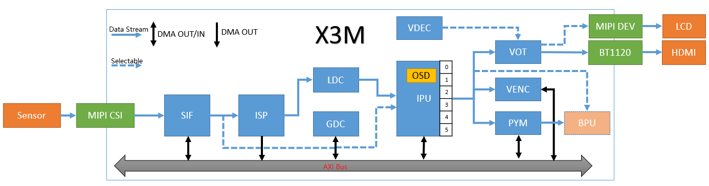
get_sif_data completes the initialization of the sensor, MIPI CSI, and SIF modules, and implements the function of acquiring video frame data from the SIF module, supporting obtaining images in both Raw and YUV formats from the SIF module.
get_sif_data can effectively assist users in debugging the lighting of the sensor and X3M. After establishing the data path from sensor to SIF, other module functions can be debugged.
Program Development
Source Code Structure
The source code is located at /app/multimedia_samples/get_sif_data
.
├── main.c                       # Main program, loads the sensor list and controls the commands
├── Makefile			 # Makefile for compilation
├── module.c
├── module.h
├── Readme.md
├── sensor_handle.c              # Sensor initialization, interface for acquiring images from SIF
├── sensor_handle.h
├── sensors			 # Sensor parameter configuration, add a new file to this directory for each new sensor
│   ├── sensor_f37.c
│   └── sensor_imx415.c
└── sensors.lds
Compilation
The current code is compiled using a Makefile.
Enter the source code directory and execute the following command to compile and generate the get_sif_data program:
$ cd sample/get_sif_data
$ make clean # Clean the source code to maintain a clean code environment
$ make
··· ··· # log
$ ls
get_sif_data  main.c  main.o  Makefile  module.c  module.h  module.o  Readme.md  sensor_handle.c  sensor_handle.h  sensor_handle.o  sensors  sensors.lds
Adding a new sensor
If there is a new sensor that needs to be debugged, please refer to the source code files in the "sensors" directory and add a new sensor configuration accordingly.
Using F37 as an example to illustrate the key code:
/*
 * Adding sensor, mipi, sif dev, isp parameter configurations
 * There are detailed comments in the code about the parameters in each struct
 * The isp parameters do not need to be concerned in this program
 */
static int set_sensor_param(void)
{
        printf("set_sensor_param\n");
        /* Define sensor's initialization attribute information */
        snsinfo = SENSOR_1LANE_F37_30FPS_10BIT_LINEAR_INFO;
        /* Define mipi's initialization attribute information */
        mipi_attr = MIPI_1LANE_SENSOR_F37_30FPS_10BIT_LINEAR_ATTR;
        /* Define dev's initialization attribute information */
        devinfo = DEV_ATTR_F37_LINEAR_BASE;
        /* Define pipe's attribute information */
        pipeinfo = PIPE_ATTR_F37_LINEAR_BASE;

        return sensor_sif_dev_init();
        return 0;
}

/*
 * The main program calls this function during the sensor module traversal to register the sensor name and sensor parameter configuration interface.
 */
static int sensor_probe(void)
{
        int i = 0;

        /* Find an empty position in sensor_lists */
        for (i = 0; i < ARRAY_SIZE(sensor_lists); i++) {
                if (0 == strlen(sensor_lists[i].sensor_tag)) break;
        }

        if (i >= ARRAY_SIZE(sensor_lists)) {
                printf("sensor lists is full\n");
                return -1;
        }
        strncpy(sensor_lists[i].sensor_tag, SENSOR_TAG, 31 > strlen(SENSOR_TAG) ? strlen(SENSOR_TAG) : 31);
        sensor_lists[i].func = set_sensor_param;
        return 0;
}

/* Register sensor's module entry, which the main program will use when traversing the sensor */
SENSOR_MODULE_INSTALL(sensor_probe);
Function Usage
Hardware Connection
The RDK X3 development board connects to the Sensor module through the mipi host interface. Ensure that you correctly connect the Sensor module according to the model being debugged.
Program Deployment
After following the compilation process above to generate get_sif_data, execute the program and, based on the prompt, select the category of the sensor currently connected to the development board. For instance, if a F37 sensor is connected, choose option 1.
Upon successful initialization, the program automatically captures and saves the first frame image (pipe0_plane0_1920x1080_frame_001.raw) in the directory where the program runs (you can view this by executing ls -l pipe0_plane0_1920x1080_frame_* after exiting the program) and prints out available user commands. The execution process looks like:
chmod +x get_sif_data
./get_sif_data

D-Robotics Sensor Test Tools V1.0

********************** Sensor Lists *************************
        0 -- IMX415
        1 -- F37
*************************************************************

Please select :1 # Select the sensor
... ... # A series of initialization logs
normal pipe_id (0)type(9)frame_id(1)buf_index(0)w x h(1920x1080) data_type 9 img_format 0
stride_size(2400) w x h1920 x 1080  size 2592000
pipe(0)dump normal raw frame id(1),plane(1)size(2592000) # Captures the first frame
filedump(pipe0_plane0_1920x1080_frame_001.raw, size(2592000) is successed
time cost 85 ms
dumpToFile raw cost time 85 ms********************** Command Lists *************************
  q     -- quit
  g     -- get one frame
  l     -- get a set frames
  h     -- print help message

Command:
Command Explanations:
- g: Acquires a single frame of the image; supports multiple consecutive acquisitions by inputting several
gs, e.g.,gggg.
Command: g
normal pipe_id (0)type(9)frame_id(4078)buf_index(5)w x h(1920x1080) data_type 9 img_format 0
stride_size(2400) w x h1920 x 1080  size 2592000
pipe(0)dump normal raw frame id(4078),plane(1)size(2592000)
filedump(pipe0_plane0_1920x1080_frame_4078.raw, size(2592000) is successed
time cost 67 ms
dumpToFile raw cost time 67 ms
- l: Continuously acquires 12 frames, equivalent to entering 12
gs.
Command: l
normal pipe_id (0)type(9)frame_id(4588)buf_index(3)w x h(1920x1080) data_type 9 img_format 0
stride_size(2400) w x h1920 x 1080  size 2592000
pipe(0)dump normal raw frame id(4588),plane(1)size(2592000)
filedump(pipe0_plane0_1920x1080_frame_4588.raw, size(2592000) is successed
time cost 56 ms
... ... # Continuous output for acquiring frame data
dumpToFile raw cost time 56 msnormal pipe_id (0)type(9)frame_id(4609)buf_index(7)w x h(1920x1080) data_type 9 img_format 0
stride_size(2400) w x h1920 x 1080  size 2592000
pipe(0)dump normal raw frame id(4609),plane(1)size(2592000)
filedump(pipe0_plane0_1920x1080_frame_4609.raw, size(2592000) is successed
time cost 57 ms
dumpToFile raw cost time 57 ms
- q: Exits the program
Command: Command: q
quit
[  256.825912] [S0][V1]sif_video_streamoff
[  256.826439] SIF close node 1
[  256.853045] [S0][V0]sif_video_streamoff SIF last process stream off
[  256.853922] [S0][V0]sif_video_streamoff
[  256.855476] hobot_dmcfreq_target: dmcfreq->rate:2666000000, target_rate:2666000000
[  256.856460] buf:performance
[  256.856460] , powersave_rate:2666000000, dmcfreq->pre_state:0
[  256.857610] [S0][V0]x3_sif_close SIF last process close
[  256.858301] SIF close node 0
[  256.858807] [isp_drv]: camera_sys_stream_off: camera_sys_stream_off success line 1549 dev_name port_0
[  256.860006] [isp_drv:cam]: camera_fop_release: line 115 port 0 user_num 0  camera_cdev->start_num 0
[  256.861229] vps mipi_host1: sensor1_mclk set(1) 0 as 24000000
[  256.861980] vps mipi_host1: sensor1_mclk set(0) 0 as 24000000
[  256.862741] vps mipi_host0: sensor0_mclk set(2) 0 as 24000000
[  256.863491] vps mipi_host0: sensor0_mclk set(1) 0 as 24000000
[  256.864241] vps mipi_host0: sensor0_mclk set(0) 0 as 24000000
Running Results Explanation
After running the program, it will acquire images named similarly to pipe0_plane0_1920x1080_frame_4609.raw or pipe0_1920x1080_frame_1024.yuv. To view these images, use the hobotplayer tool with the following configuration settings:
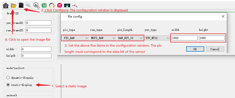
- Viewing RAW Images:
Configure options as shown in the figure below, focusing on pic_type, raw_type, pix_length, width, and height. For F37, configure as (PIC_RAW, MIPI_RAW, RAW_BIT_10, 1920, 1080), and for IMX415, configure as (PIC_RAW, MIPI_RAW, RAW_BIT_12, 3840, 2160).
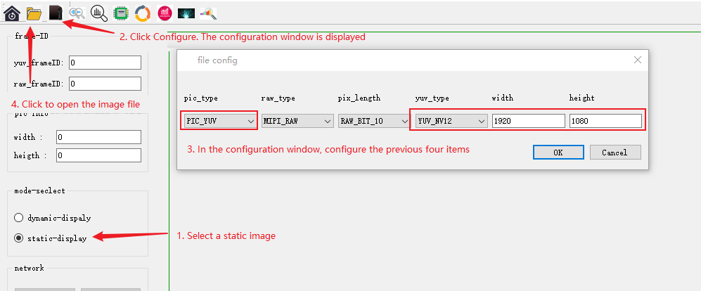
- Viewing YUV Images:
Configure options as per the steps shown, paying attention to pic_type, yuv_type, width, and height. For F37, configure as (PIC_YUV, YUV_NV12, 1920, 1080), and for IMX415, configure as (YUV_NV12, 3840, 2160).
get_isp_data Usage Guide
Functionality
The following diagram illustrates the video data path for the X3M, with technical terms explained in the Multimedia Development Overview - Terminology.
The get_isp_data function initializes the sensor, MIPI CSI, SIF, and ISP modules, enabling the retrieval of video frame data from the ISP module. It supports obtaining images in YUV format from the ISP.
get_isp_data effectively aids users in debugging sensor and X3M ISP performance. After establishing a data flow from sensor -> SIF -> ISP, it facilitates the testing of other module functionalities.
Programming
Source Code Structure
The source code is located at /app/multimedia_samples/get_isp_data.
.
├── main.c                       # Main program, loads sensor list and provides command control
├── Makefile			 # Build configuration file
├── module.c
├── module.h
├── Readme.md
├── sensor_handle.c              # Interface for sensor initialization and image retrieval from ISP
├── sensor_handle.h
├── sensors			 # Sensor configuration, add new files for each new sensor in this directory
│   ├── sensor_f37.c
│   └── sensor_imx415.c
└── sensors.lds
Compilation
The current code uses a Makefile for configuration. To compile and generate the get_isp_data program, navigate to the source code directory and execute:
$ cd /app/multimedia_samples/get_sif_data
$ make clean # Clear the source code for a clean development environment
$ make
... ... # Compilation output
$ ls
get_isp_data  main.c  main.o  Makefile  module.c  module.h  module.o  Readme.md  sensor_handle.c  sensor_handle.h  sensor_handle.o  sensors  sensors.lds
Adding a new sensor
If there is a new sensor that needs to be debugged, please refer to the source code files in the "sensors" directory and add a new sensor configuration accordingly.
Take F37 as an example to explain the key code:
/*
 * Add sensor, mipi, sif dev, and isp parameter configuration
 * The structure parameters have detailed comments in the code
 */
static int set_sensor_param(void)
{
        printf("set_sensor_param\n");
        /* Define sensor initialization attributes */
        snsinfo = SENSOR_1LANE_F37_30FPS_10BIT_LINEAR_INFO;
        /* Define mipi initialization parameters */
        mipi_attr = MIPI_1LANE_SENSOR_F37_30FPS_10BIT_LINEAR_ATTR;
        /* Define dev initialization attributes */
        devinfo = DEV_ATTR_F37_LINEAR_BASE;
        /* Define pipe attributes */
        pipeinfo = PIPE_ATTR_F37_LINEAR_BASE;
    	/* Define dis attributes */
    	disinfo = DIS_ATTR_F37_BASE;
    	/* Define ldc attributes */
    	ldcinfo = LDC_ATTR_F37_BASE;
        return sensor_sif_dev_init();
        return 0;
}
```/*
 * This function is called by the main program to register the sensor name and sensor parameter configuration interface when traversing the sensor module.
 */
static int sensor_probe(void)
{
        int i = 0;

        /* Find an empty position in sensor_lists */
        for (i = 0; i < ARRAY_SIZE(sensor_lists); i++) {
                if (0 == strlen(sensor_lists[i].sensor_tag)) break;
        }

        if (i >= ARRAY_SIZE(sensor_lists)) {
                printf("sensor lists is full\n");
                return -1;
        }

        strncpy(sensor_lists[i].sensor_tag, SENSOR_TAG, 31 > strlen(SENSOR_TAG) ? strlen(SENSOR_TAG) : 31);
        sensor_lists[i].func = set_sensor_param;
        return 0;
}

/* Register the entry point of the sensor module, which will be used by the main program when traversing the sensor */
SENSOR_MODULE_INSTALL(sensor_probe);
Function Usage
Hardware Connection
The RDK X3 development board is connected to the Sensor module through the mipi host interface. Please connect it correctly according to the current sensor module model being debugged.
Program Deployment
After generating get_isp_data according to the above compilation process, execute the program and select the current sensor category that is connected to the development board correctly according to the prompt. For example, if the currently connected sensor is the F37 sensor, select 1.
If the initialization is successful, the first frame image (pipe0_1920x1080_frame_001.yuv) will be automatically saved in the directory where the program runs (you can check it by executing ls -l pipe0_1920x1080_frame_* after exiting the program), and the commands that the user can use will be printed. The running process is as follows:
chmod +x get_isp_data
./get_isp_data

D-Robotics Sensor Test Tools V1.0

********************** Sensor Lists *************************
        0 -- IMX415
        1 -- F37
*************************************************************
Please select: 1 # Select sensor
... ... # A long string of initialization logs
normal pipe_id (0)type(11)frame_id(1)buf_index(0)w x h(1920x1080) data_type 11 img_format 0
stride_size(2400) w x h1920 x 1080 size 2073600
pipe(0)dump normal yuv frame id(1),plane(1)size(2073600) # Get the first frame image
filedump(pipe0_1920x1080_frame_001.yuv, size(2073600) is successed
time cost 63 ms
dumpToFile yuv cost time 63 ms********************** Command Lists *************************
  q     -- quit
  g     -- get one frame
  l     -- get a set frames
  h     -- print help message
Command:
Command explanation:
- g: Get one frame image, supports inputting multiple 'g' to continuously get images, for example, input 'gggg'
Command: g
normal pipe_id (0)type(11)frame_id(4078)buf_index(5)w x h(1920x1080) data_type 11 img_format 0
stride_size(2400) w x h1920 x 1080 size 2073600
pipe(0)dump normal yuv frame id(4078),plane(1)size(2073600)
filedump(pipe0_1920x1080_frame_4078.yuv, size(2073600) is successed
time cost 63 ms
dumpToFile yuv cost time 63 ms
- l: Get 12 frames continuously, equivalent to inputting 12 'g'
Command: l
normal pipe_id (0)type(11)frame_id(4588)buf_index(3)w x h(1920x1080) data_type 11 img_format 0
stride_size(2400) w x h1920 x 1080 size 2073600
pipe(0)dump normal yuv frame id(4588),plane(1)size(2073600)
filedump(pipe0_1920x1080_frame_4588.yuv, size(2073600) is successed
time cost 56 ms
... ... # Continuously printing frame data
dumpToFile yuv cost time 56 msnormal pipe_id (0)type(11)frame_id(4609)buf_index(7)w x h(1920x1080) data_type 11 img_format 0
stride_size(2400) w x h1920 x 1080 size 2073600
pipe(0)dump normal yuv frame id(4609),plane(1)size(2073600)
filedump(pipe0_1920x1080_frame_4609.yuv, size(2073600) is successed
time cost 57 ms
dumpToFile yuv cost time 57 ms
- q: Quit the program
Command: Command: q
quit
[  256.825912] [S0][V1]sif_video_streamoff
[  256.826439] SIF close node 1
[  256.853045] [S0][V0]sif_video_streamoff SIF last process stream off
[  256.853922] [S0][V0]sif_video_streamoff
[  256.855476] hobot_dmcfreq_target: dmcfreq->rate:2666000000, target_rate:2666000000
[  256.856460] buf:performance
[  256.856460] , powersave_rate:2666000000, dmcfreq->pre_state:0
[  256.857610] [S0][V0]x3_sif_close SIF last process close
[  256.858301] SIF close node 0
[  256.858807] [isp_drv]: camera_sys_stream_off: camera_sys_stream_off success line 1549 dev_name port_0
[  256.860006] [isp_drv:cam]: camera_fop_release: line 115 port 0 user_num 0  camera_cdev->start_num 0
[  256.861229] vps mipi_host1: sensor1_mclk set(1) 0 as 24000000
[  256.861980] vps mipi_host1: sensor1_mclk set(0) 0 as 24000000
[  256.862741] vps mipi_host0: sensor0_mclk set(2) 0 as 24000000
[  256.863491] vps mipi_host0: sensor0_mclk set(1) 0 as 24000000
[  256.864241] vps mipi_host0: sensor0_mclk set(0) 0 as 24000000
Explanation of Running Effect
After running the program, you will obtain a yuv image named pipe0_1920x1080_frame_4609.yuv.
Please use the hobotplayer tool to view the image. The configuration of the image is as follows:
- View the YUV image
Configure the options as shown below, paying attention to the configuration of pic_type, yuv_type, width, and height in the file config. F37 configuration is (PIC_YUV, YUV_NV12, 1920, 1080), IMX415 configuration is (YUV_NV12, 3840, 2160).
Sample_isp User Manual
Program Function
The sample_isp program initializes the isp image interface. Its main function is to dynamically set/get parameters for each isp image and return the test result.
Program Development
Source Code Structure
The source code is located at /app/multimedia_samples/sample_isp.
.```
├── main.c			# Main program
├── Makefile			# Compilation makefile
└── Readme.md			# Program instructions
Compilation
The current code is compiled through a Makefile.
Enter the source code directory and execute the following command to compile and generate sample_isp:
$ cd /app/multimedia_samples/sample_isp
$ make clean # Clean the source code to maintain a clean code environment
$ make
... ... # A lot of compilation prints
$ ls
main.c  main.o  Makefile  sample_isp
Function Usage
Program Deployment
After generating sample_isp according to the above compile process, run the program.
Note that the sensor program needs to be running before running this program. The sensor program can be run directly using Sunrise_camera. The process of running sample_isp is as follows:
chmod +x sample_isp
# ./sample_isp
============================================
APP: ./sample_isp
a: AE
b: AF
c: AWB
d: BL
e: DEMOSAIC
f: SHARPEN
g: GAMMA
h: IRIDIX
i: CNR
j: SINTER
k: TEMPER
l: SCENE_MODES
m: FIRMWARE STATE
n: MODULE CONTROL
o: REGISTER
p: LIBREG_AE
q: LIBREG_AWB
```r: LIBREG_AF
s: METERING AE(read only)
t: METERING AWB(read only)
u: METERING AF(read only)
v: METERING AE_5BIN(read only)
w: METERING_DATA_TIME(read only)
x: SWITCH SCENE
A: CSC
B: MESH SHADING
C: MESH SHADING LUT
D: RADIAL SHADING
E: RADIAL SHADING LUT
F: IRIDIX STRENGTH LEVEL
G: IDX_IRQ_SYNC
H: IDX_AWB_ZONE
I: IDX_AF_ZONE
L: IDX_AF_KERNEL
M: IDX_AEROI_INFO
N: IDX_LUMA_INFO
O: IDX_AEPARAM_INFO
J: IDX_AE5BIN_ZONE
K: IDX_AE_ZONE
P: IDX_AE_EX
y: Help
Q: Exit
============================================
ISP_TEST>
Command Explanation:
-
a: Get/Set AE properties
-
b: Not supported in the example
-
c: Get/Set AWB properties
-
d: Get/Set BlackLevel properties
-
e: Get/Set Demosaic properties
-
f: Get/Set SHARPEN properties
-
g: Get/Set GAMMA properties
-
h: Get/Set IRIDIX properties
-
i: Get/Set CNR properties
-
j: Get/Set SINTER properties- k: Get/Set TEMPER attribute
-
l: Get/Set SCENE_MODES attribute
-
m: Get/Set FWSTATE attribute
-
n: Get/Set ModuleControl attribute
-
o: Get/Set Register register
-
p: Register AE callback interface
-
q: Register AWB callback interface
-
r: Register AF callback interface
-
s: Get AE statistics information
-
t: Get AWB statistics information
-
u: Get AF statistics information
-
v: Get AE_5BIN statistics information
-
w: Get the latest statistics information (by default, the code gets AWB, can be changed to AE or AF statistics information by passing parameters)
-
x: Switch ISP effect library (the so library needs to be in the same directory as the isp_test file)
-
A: Get/Set CSC attribute
-
B: Get/Set MESH_SHADING attribute
-
C: Get/Set MESH SHADING LUT attribute
-
D: Get/Set RADIAL SHADING attribute
-
E: Get/Set RADIAL SHADING LUT attribute
-
F: Get/Set IRIDIX STRENGTH LEVEL attribute
-
G: Get frame synchronization start/end time
-
H: Set AWB_ZONE attribute
-
I: Set AF_ZONE attribute
-
L: Get/Set AF_KERNEL_INFO attribute
-
M: Get/Set AEROI information- N: Get LUMA information
-
O: Get/set AEParam information
-
J: Set AE5BIN_ZONE attribute
-
K: Set AEZONE attribute
-
P: Get/set additional AE properties
-
y: Help information
-
Q: Exit program
sample_vps Instructions
Program Functionality
The sample_vps program uses multiple channels of a vps grp to perform operations such as cropping, rotation, scaling, etc. on YUV images, demonstrating the basic usage of vps. For more advanced image processing using vps, please refer to the Video Processing chapter.
Program Development
Source Code Structure
The source code is located at: /app/multimedia_samples/sample_vps
.
|-- 19201080.yuv      # Source file in NV12 format for playback
|-- main.c            # Main program
`-- Makefile          # Compilation makefile
Compilation
The current code is compiled using a Makefile.
To compile and generate the sample_vps, enter the source code directory and execute the following commands:
$ cd /app/multimedia_samples/sample_vps
$ make clean # Clean the source code to maintain a clean code environment
$ make
... ... # A long printout of the compilation process
$ ls
19201080.yuv  main.c  main.o  Makefile  sample_vps
Functionality Usage#### Program Deployment
Generate sample_vps according to the above compilation process, and make sure that 19201080.yuv exists in the current directory. Then execute the program ./sample_vps.
Description of Running Effects
The YUV image is processed using vps for cropping, rotation, scaling, and other functions, and the corresponding processed YUV images are saved.
grp_0_chn_1_out_1280_720.yuvis the original image cropped to a resolution of1280x720;grp_0_chn_2_out_1088_1920.yuvis the image rotated 90 degrees from the original image;grp_0_chn_3_out_960_540.yuvis the original image resized to a resolution of960x540;grp_0_chn_5_out_2880_1620.yuvis the original image enlarged to a resolution of2880x1620;
sample_vps_zoom Instructions
Program Function
The sample_vps_zoom program uses the ipu and pym hardware modules of vps to zoom in on multiple areas of the YUV image, encode the processed YUV image into an H264 video stream, and preview it directly using tools such as MPC-BE. It is similar to the zoom function in an electronic gimbal. The entire program's Pipeline is shown in the following figure:
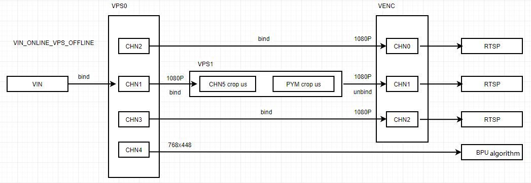
As shown in the Pipeline, the program reads the YUV image through vps0, binds vps0 chn1 and vps1, processes it through crop and enlargement using ipu and pym, and sends the data to venc chn1 for H264 encoding to achieve the zoom effect. At the same time, vps0 chn2 is bound to venc chn0 for H264 encoding, and vps0 chn3 is bound to venc chn2 for H264 encoding.
Program Development
Source Code Structure
The source code is located at: /app/multimedia_samples/sample_vps_zoom
.
|-- 19201080.yuv      # The NV12 format file used for feedback
|-- main.c            # Main program
`-- Makefile          # Compilation Makefile
Compilation
The current code is compiled and built through a Makefile configuration.
Go to the source code directory and execute the following command to compile and generate the sample_vps_zoom program:
$ cd /app/multimedia_samples/sample_vps_zoom
$ make clean # Clean the source code to keep a clean code environment
$ make
... ... # A long segment of compilation printing
$ ls
19201080.yuv  main.c  main.o  Makefile  sample_vps_zoom
Function Usage#### Program Deployment
Generate sample_vps_zoom according to the above compilation process, making sure that the 19201080.yuv file exists in the current directory.
Execute the program ./sample_vps_zoom.
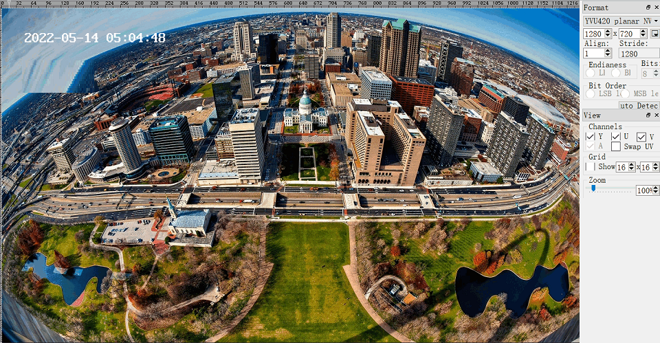
Running Effects Description
The YUV image is encoded into a smooth zoom H264 stream by using the backfill method and the ipu, pym, venc modules. The effect is shown below.

sample_osd Instructions
Program Function
The sample_osd program is used to overlay timestamps and Chinese text osd on the YUV data output from the vps channel. For more advanced osd image processing, please refer to the Region Processing section.
Program Development
Source Code Structure
The source code is located at: /app/multimedia_samples/sample_osd
.
|-- 1280720.yuv       # Backfill using NV12 format file
|-- main.c            # Main program
|-- Makefile          # Compilation makefile
Compilation
The current code is compiled through a Makefile file configuration.
Enter the source code directory and execute the following command to compile and generate the sample_osd program.
$ cd sample/sample_osd
$ make clean # Clean the source code to maintain a clean code environment
$ make
... ... # A long compilation log
$ ls
1280720.yuv  main.c  main.o  Makefile  sample_osd
Function Usage
Program DeploymentAfter generating sample_osd according to the above compilation process, make sure that 1280720.yuv exists in the current directory, and then execute sample_osd.
Running Effect Description
The YUV image output by the vps channel after overlaying osd is shown in the following figure:
Usage of sample video codec
Program Functions
-
sample_vdec_basicimplements the basic decoding function, reads localH264/H265/MJPEGfiles, decodes and saves theNV12result. -
sample_venc_basicimplements the basic encoding function, readsNV12images, encodes them intoH264(orH265orMJPEG), and saves them as local files. -
sample_vdec_two_channelis targeted at scenes that require decoding multiple channels at the same time. It adds a decoding channel on the basis ofsample_vdec_basicto achieve dual-channel decoding. It reads localH264/H265/MJPEGfiles and decodes them concurrently, saving them asNV12files separately. -
sample_venc_two_channelis targeted at scenes that require encoding multiple channels at the same time. It adds an encoding channel on the basis ofsample_venc_basicto achieve dual-channel encoding. It reads localNV12files and encodes them concurrently, saving them asH264(orH265orMJPEG).
Program Development
Source Code Structure
The source code is located at: /app/multimedia_samples/sample_video_codec
.
├── example_vdec_basic
├── example_vdec_two_channel
├── example_venc_basic
├── example_venc_two_channel
├── Makefile
├── README.md
├── sample_vdec_basic.c
├── sample_vdec_two_channel.c
├── sample_venc_basic.c
└── sample_venc_two_channel.c
Compilation
The current code is configured to compile through a Makefile.
Enter the source code directory and execute the following command to compile and generate sample_venc_basic, sample_vdec_basic, sample_vdec_two_channel, and sample_venc_two_channel programs.
$ cd /app/multimedia_samples/sample_video_codec
$ make clean # Clean the source code to maintain a clean code environment
$ make... ... # A long compilation printout
$ ls
example_vdec_basic        example_venc_basic        Makefile   sample_vdec_basic    sample_vdec_two_channel    sample_venc_basic    sample_venc_two_channel
example_vdec_two_channel  example_venc_two_channel  README.md  sample_vdec_basic.c  sample_vdec_two_channel.c  sample_venc_basic.c  sample_venc_two_channel.c
Program Deployment
sample_vdec_basic
After generating the sample_vdec_basic program using the compilation process described above,
execute ./sample_vdec_basic -w width -h height -t ecode_type -f file
where width represents the number of pixels in the image's width,
height represents the pixel format in the image's height,
encode_type can be h264\h265\mjpeg,
and file is the name of the file to be decoded.
sample_venc_basic
After generating the sample_venc_basic program using the compilation process described above,
execute ./sample_venc_basic -w width -h height -t ecode_type -f file0 -g file1
where width represents the number of pixels in the image's width,
height represents the pixel format in the image's height,
ecode_type can be h264\h265\mjpeg,
file0 is the name of the file to be encoded and it needs to be in NV12 format,
file1 is the name of the file to be encoded and it needs to be in NV12 format. Its width and height should be the same as file0.
sample_vdec_two_channel
After generating the sample_vdec_two_channel program using the compilation process described above,
execute ./sample_vdec_two_channel -w width -h height -t ecode_type -f file
where width represents the number of pixels in the image's width,
height represents the pixel format in the image's height,
ecode_type can be h264\h265\mjpeg.#### sample_venc_two_channel
After generating the sample_venc_two_channel program according to the compilation process above,
Execute ./sample_venc_two_channel -w width -h height -t ecode_type -f file0 -g file1
Where width is the number of pixels in the image width,
height is the pixel format contained in the image height,
ecode_type can be h264\h265\mjpeg,
file0 is the file name to be encoded and needs to be in NV12 format,
file1 is the file name to be encoded and needs to be in NV12 format, and its width and height need to be the same as file0.
Running Effect Description
sample_vdec_basic
Generates decode.nv12 in the current running directory, the content of this file is updated with the decoding content.
sample_venc_basic
Generates sample_venc.h264/sample_venc.h265/sample_venc.jpg in the current running directory. The H264/H265 files show alternative display of file1 and file2.
sample_vdec_two_channel
Generates sample_decode_ch0.nv12 and sample_decode_ch1.nv12 in the current running directory, the content of these files is updated with the decoding content.
sample_venc_two_channel
Generates sample_venc_ch0.h264(sample_venc_ch0.h265/sample_venc_ch0.jpg) and sample_venc_ch1.h264(sample_venc_ch1.h265/sample_venc_ch1.jpg) in the current running directory. The H264/H265 files show alternative display of file1 and file2.
sample_vot Usage Instructions
Program Function
The sample_vot program initializes the VOT module and implements the function of reading an nv12 image data frame from the current directory and sending it to the VOT bt1120 output display.
Program Development
Source Code Structure
The source code is located in:/app/multimedia_samples/sample_vot
.```

├── 1280_720yuv8.yuv                      # Playback using 720P NV12 format file
├── 1920_1080yuv8.yuv                     # Playback using 1080P NV12 format file
├── Makefile                               # Compile makefile
├── Readme.md                              # Program instructions
└── vot.c                                  # Main program
Compilation
The current code is compiled through a Makefile.
Enter the source code directory and execute the following command to compile and generate sample_vot.
cd /app/multimedia_samples/sample_vot
$ make clean # Clean the source code to maintain a clean code environment
$ make
... ... # A large block of compilation prints
$ ls
1280_720yuv8.yuv  1920_1080yuv8.yuv  Makefile  Readme.md  sample_vot  vot.c  vot.o
Function Usage
Program Deployment
Compile the code according to the above compilation process to generate sample_vot
Execute the program ./sample_vot 1080P30.
chmod +x sample_vot
root@x3sdbx3-samsung2G-3200:/userdata# ./sample_vot 1080P60
[   26.051955] channel id is 0, enable is 0, reg value is 0x4ef00f.
[   26.052744] channel id is 1, enable is 0, reg value is 0x4ef00f.
[   26.053520] channel id is 2, enable is 0, reg value is 0x4ef00f.
[   26.054339] channel id is 3, enable is 0, reg value is 0x4ef00f.
stLayer width:1920[   26.055263] channel id is 0, enable is 1, reg value is 0x14ef00f.
stLayer height:1080
libiar: hb_disp_set_timing done!
stChnAttr priority :2
stChnAttr src width :1920
stChnAttr src height :1080
stChnAttr s32X :0
stChnAttr s32Y :0
stChnAttr u32DstWidth :1920
stChnAttr u32DstHeight :1080
[   26.056165] iar_output_stream.
stCrop width :1920
stCrop height :1080
[   26.059304] channel id is 0, enable is 1, reg value is 0x14ef00f.
framesize:3110400

(Note: If using X3 SDB board, the supported parameters are only 1080P60/1080P30. If using the sil902x's bt1120 to hdmi chip, the parameters can be as follows:
	1080P60
	1080P59.94
	1080P50
	1080P30
	1080P29.97
	1080P25
	1080I60
	1080I59.94
	1080I50
	720P60
	720P59.94
	720P50
	720P29.97)
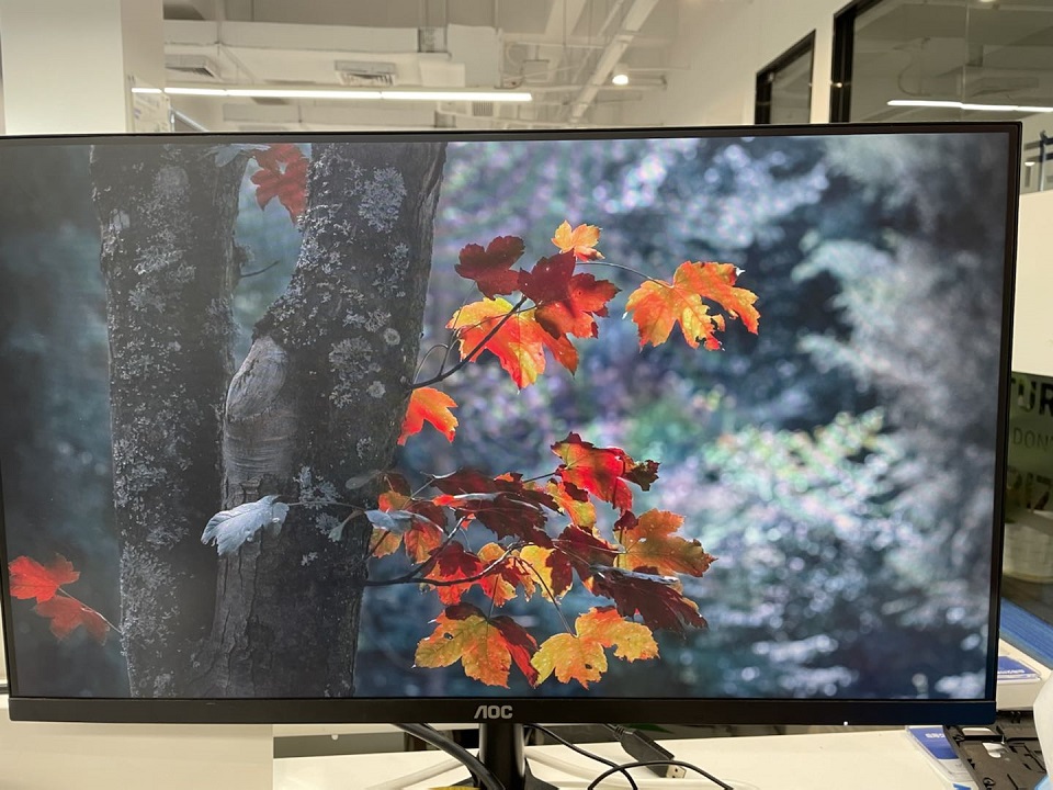
Running Effect Description
The program reads the 1920_1080yuv8.yuv file into memory and sends the data to the bt1120 interface of the VOT module through the interface, and then outputs the hdmi effect to the display device through the hdmi conversion chip as shown in the following figure.
sample_lcd Usage Instructions
Program Function
The sample_lcd program initializes the VOT module and reads one frame of NV12 picture data from the current directory and sends it to VOT's midi-dsi output to display on the lcd screen.
Program Development
Source Code Structure
The source code is located at: /app/multimedia_samples/sample_lcd
.
├── 720x1280.yuv	# NV12 format file for playback
├── Makefile		# Compilation makefile
├── Readme.md		# Program instructions
└── vot.c			# Main program
CompilationThe current code is compiled and configured through a Makefile file.
Go to the source code directory and execute the following commands to compile and generate the sample_lcd program:
$ cd /app/multimedia_samples/sample_lcd
$ make clean # Clean the source code to maintain a clean code environment
$ make
... ... # A long compilation output
$ ls
720x1280.yuv  vot.c  vot.o  Makefile  sample_lcd
Function Usage
Program Deployment
Follow the above compilation process to generate the sample_lcd program and ensure that the 720x1280.yuv file exists in the current directory.
Run the program ./sample_lcd.
chmod +x sample_lcd
# ./sample_lcd
root@x3sdbx3-samsung2G-3200:/userdata# ./sample_lcd
libiar: hb_disp_set_timing done!
HB_VOT_SetChnAttr 0: 0
HB_VOT_EnableChn: 0
HB_VOT_EnableChn: 0
framesize:1382400
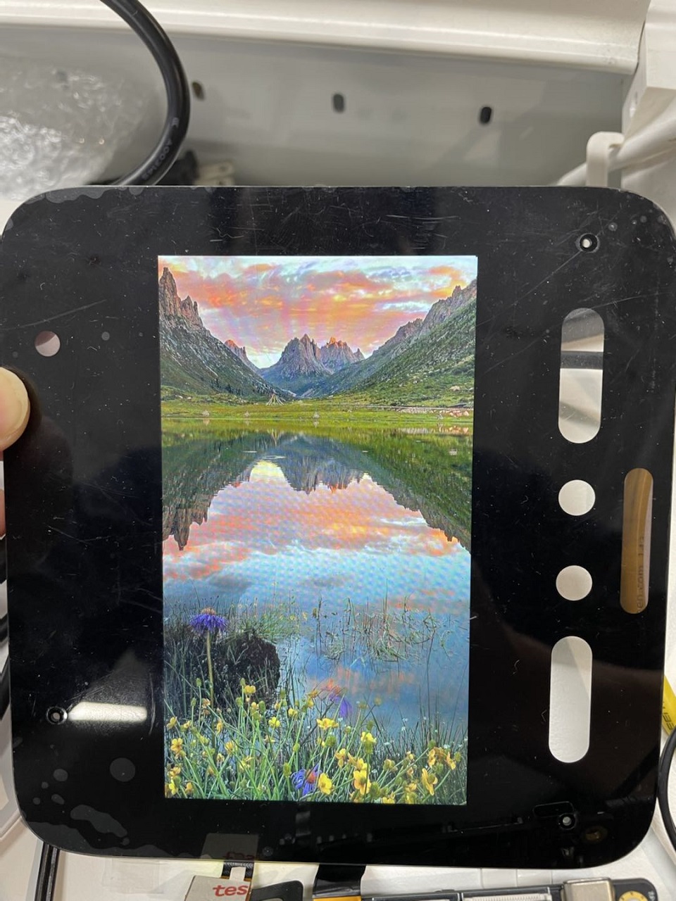
Running Effect Explanation
The program reads the 720x1280.yuv file into memory and sends the data to the VOT module's midi-dsi interface through an interface, and then displays it on the lcd screen device as shown in the following image.