7.3.12 Multimedia Performance Debugging
Overview
Camera is the main external source of image data, and the VIO software is a relatively opaque internal software that mainly provides relevant images and information to internal applications. The internal image processing IP information of the XJ3 chip is roughly as follows:
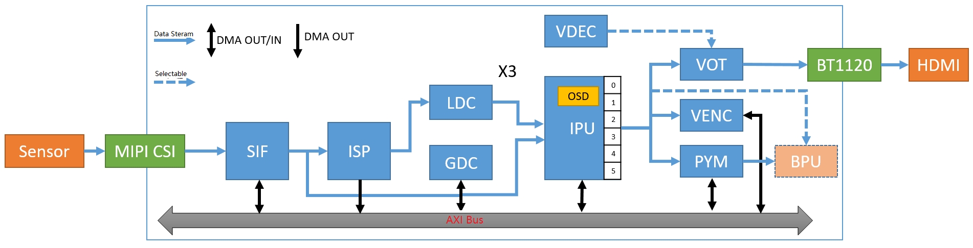
| Input Method | IP | Output Method |
|---|---|---|
| Online | MIPI | Online |
| Online/Offline | SIF | Online/Offline |
| Online | ISP | Online/Offline |
| Online | LDC | Online |
| Offline | GDC | Offline |
| Online/Offline | IPU | Online/Offline |
| Online/Offline | PYM | Offline |
Note: Online means data exchange through on-chip RAM, and Offline means data exchange through DDR.
This chapter mainly describes the adjustment of DDR priority and other relevant parameters for the commonly used scenarios of X3 chip's image data processing path and other modules based on DDR bandwidth and latency.
When the instantaneous DDR bandwidth is insufficient, it will cause video frame loss. Between the frame rate and frame loss, a suitable configuration value can be selected to balance them based on the description in this chapter.
DDR Master QoS
The modules of XJ3 access DDR through the AXI interface. XJ3 has 8 AXI interfaces, namely AXI_0 ~ AXI_7. The relationship between XJ3's modules and the AXI interfaces is as follows:
| Port Number | AXI_0 | AXI_1 | AXI_2 | AXI_3 | AXI_4 | AXI_5 | AXI_6 | AXI_7 |
|---|---|---|---|---|---|---|---|---|
| Module Name | CPU/R5 | NOC | CNN0 | CNN1 | VIO0 | VPU/JPU | VIO1 | PERI |
AXI_4 and AXI_6 are configurable, and the VIO sub-modules can be configured to AXI_4 or AXI_6 through registers. AXI_6 has a higher priority.
XJ3 VIO includes the following sub-modules: SIF_W, ISP0_M0, ISP0_M2, GDC0, DIS, SIF_R, IPU0, PYM, IAR.
AXI QoS Control
The priority range of AXI QoS is 0 to 15, and the higher the value, the higher the priority. After the XJ3 system is started, the read and write QoS default configuration is 0x2021100.
The priority value of each port is set through the DDR_PORT_READ/WRITE_QOS_CTRL registers of the Perf Monitor, and then the Perf Monitor sets it to the DDR controller through hardware. The DDR controller does not need to be set by software.
The value of DDR QoS is set and queried in the DDR_Monitor driver through the attribute file of Sysfs.
It can be set through the "all" attribute file at once, where the lowest 4 bits correspond to P0_CPU, and the highest 4 bits correspond to P7_PERI.
It is also possible to set and query the priorities of individual ports separately, such as cpu, bifdma, bpu0, bpu1, vio0, vpu, vio1, peri, as follows:QoS sysfs interface
# Query read QoS:
cat /sys/bus/platform/drivers/ddr_monitor/read_qos_ctrl/all

CPU port is not allowed to be configured in runtime.
You can run chmod +w as root for debugging purpose.
****************************************************

04032221:
P0_CPU:     1
P1_BIFDMA:  2
P2_CNN0:    2
P3_CNN1:    2
P4_VIO0:    3
P5_VPU:     0
P6_VIO1:    4
P7_PERI:    0
cat /sys/bus/platform/drivers/ddr_monitor/write_qos_ctrl/all

****************************************************
CPU port is not allowed to be configured in runtime.
You can run chmod +w as root for debugging purpose.
****************************************************

04032211:
P0_CPU:     1
P1_BIFDMA:  1
P2_CNN0:    2
P3_CNN1:    2
P4_VIO0:    3
P5_VPU:     0
P6_VIO1:    4
P7_PERI:    0
# Set bifdma read QoS to 2:
echo 2 > /sys/bus/platform/drivers/ddr_monitor/read_qos_ctrl/bifdma
# Set bpu0 read QoS to 1:
echo 1 > /sys/bus/platform/drivers/ddr_monitor/read_qos_ctrl/bpu0
# Set bpu1 read QoS to 1:
echo 1 > /sys/bus/platform/drivers/ddr_monitor/read_qos_ctrl/bpu1
# Set vio0 read QoS to 2:
echo 2 > /sys/bus/platform/drivers/ddr_monitor/read_qos_ctrl/vio0
# Set VPU read QoS to 0:
echo 0 > /sys/bus/platform/drivers/ddr_monitor/read_qos_ctrl/vpu
# Set VIO1 read QoS to 3:
echo 3 > /sys/bus/platform/drivers/ddr_monitor/read_qos_ctrl/vio1
# Set PERI read QoS to 0:
echo 0 > /sys/bus/platform/drivers/ddr_monitor/read_qos_ctrl/peri
# Set BIFDMA write QoS to 2:
echo 2 > /sys/bus/platform/drivers/ddr_monitor/write_qos_ctrl/bifdma
# Set BPU0 write QoS to 1:
echo 1 > /sys/bus/platform/drivers/ddr_monitor/write_qos_ctrl/bpu0
# Set BPU1 write QoS to 1:
echo 1 > /sys/bus/platform/drivers/ddr_monitor/write_qos_ctrl/bpu1
# Set VIO0 write QoS to 2:
echo 2 > /sys/bus/platform/drivers/ddr_monitor/write_qos_ctrl/vio0
# Set VPU write QoS to 0:
echo 0 > /sys/bus/platform/drivers/ddr_monitor/write_qos_ctrl/vpu
# Set VIO1 write QoS to 3:
echo 3 > /sys/bus/platform/drivers/ddr_monitor/write_qos_ctrl/vio1
# Set PERI write QoS to 0:
echo 0 > /sys/bus/platform/drivers/ddr_monitor/write_qos_ctrl/peri
VIO Submodule Configuration
The XJ3 VIO submodule includes SIF_W, ISP0_M0, ISP0_M2, GDC0, DIS, SIF_R, IPU0, PYM, and IAR, corresponding to SIF module write, ISP write, ISP Temper read/write, GDC0 read/write, DIS write, SIF module read, IPU0 module read/write, PYM module read/write, and IAR module read/write.
These submodules can be configured to VIO0 or VIO1 using the AXIBUS register. By default, the XJ3 system configures IAR and SIF_W to VIO1, while the other modules are configured to VIO0. The submodules correspond to bit31~bit16 of the AXIBUS register as shown in the following figure:
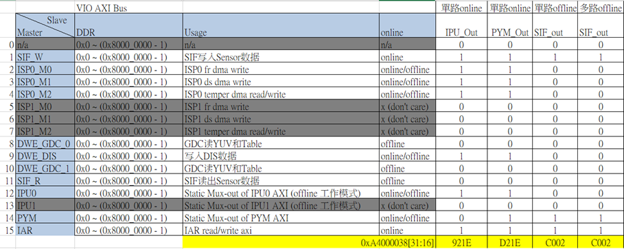
The grayed-out modules do not exist, and the corresponding bit is set to 1, indicating that the submodule is configured to VIO1. Otherwise, it is configured to VIO0. The "all" attribute can be used to configure or query all submodules at once, where the modules on VIO1 are returned, and the other modules are on VIO0. It is also possible to configure or query individual submodules using their respective attributes.
AXIBUS sys interface
# Set, value 1 configures to vio1, value 0 configures to vio0
echo 0xc0020000 > /sys/bus/platform/drivers/ddr_monitor/axibus_ctrl/all
echo 0 > /sys/bus/platform/drivers/ddr_monitor/axibus_ctrl/sifr
echo 0 > /sys/bus/platform/drivers/ddr_monitor/axibus_ctrl/isp0m0
echo 0 > /sys/bus/platform/drivers/ddr_monitor/axibus_ctrl/isp0m1
echo 0 > /sys/bus/platform/drivers/ddr_monitor/axibus_ctrl/isp0m2
echo 0 > /sys/bus/platform/drivers/ddr_monitor/axibus_ctrl/t21
echo 0 > /sys/bus/platform/drivers/ddr_monitor/axibus_ctrl/gdc0
echo 0 > /sys/bus/platform/drivers/ddr_monitor/axibus_ctrl/gdc1
echo 1 > /sys/bus/platform/drivers/ddr_monitor/axibus_ctrl/iar
echo 1 > /sys/bus/platform/drivers/ddr_monitor/axibus_ctrl/pym
echo 1 > /sys/bus/platform/drivers/ddr_monitor/axibus_ctrl/sifw
echo 0 > /sys/bus/platform/drivers/ddr_monitor/axibus_ctrl/ipu0
# Read, print all modules configured on vio1, other modules on vio0
cat /sys/bus/platform/drivers/ddr_monitor/axibus_ctrl/all axibus: 0xc0020000: sifw: vio1 pym: vio1 iar: vio1
# Module Read
cat /sys/bus/platform/drivers/ddr_monitor/axibus_ctrl/sifr axibus: 0xc0020000: sifr: vio0
cat /sys/bus/platform/drivers/ddr_monitor/axibus_ctrl/sifw axibus: 0xc0020000: sif: vio1
cat /sys/bus/platform/drivers/ddr_monitor/axibus_ctrl/isp0m0 axibus: 0xc0020000: isp_0_m0: vio0
cat /sys/bus/platform/drivers/ddr_monitor/axibus_ctrl/isp0m1 axibus: 0xc0020000: isp_0_m1: vio0
cat /sys/bus/platform/drivers/ddr_monitor/axibus_ctrl/isp0m2 axibus: 0xc0020000: isp_0_m2: vio0
cat /sys/bus/platform/drivers/ddr_monitor/axibus_ctrl/gdc0 axibus: 0xc0020000: gdc_0: vio0
cat /sys/bus/platform/drivers/ddr_monitor/axibus_ctrl/gdc1 axibus: 0xc0020000: gdc_1: vio0
cat /sys/bus/platform/drivers/ddr_monitor/axibus_ctrl/t21 axibus: 0xc0020000: t21: vio0
cat /sys/bus/platform/drivers/ddr_monitor/axibus_ctrl/ipu0 axibus: 0xc0020000: ipu0: vio0
cat /sys/bus/platform/drivers/ddr_monitor/axibus_ctrl/pym axibus: 0xc0020000: pym: vio1
cat /sys/bus/platform/drivers/ddr_monitor/axibus_ctrl/iar axibus: 0xc0020000: iar: vio1
SIF HBlank Setting
SIF reads the image line by line and sends it to ISP for processing. By increasing the horizontal blanking (HBlank), it is possible to delay the output of the next line, giving more time for ISP or other modules to process.
The default HBlank value for XJ3 SIF is 10.
HBlank affects the frame rate, and the relationship with the frame rate is as follows:
time = ((width + hblank * 32) * height) / (clock * 1000)
# clock is the ISP frequency, default to 544M.
Taking 4K as an example, the calculation is as follows:
time = ((width + hblank * 32) * height) / (clock * 1000)
| Image Width | HBlank (register) | Image Height | Clock (MHz) | Time (ms) | FPS |
|---|---|---|---|---|---|
| 3840 | 10 | 2160 | 544 | 16.5176 | 60.54 |
| 3840 | 40 | 2160 | 544 | 20.3294 | 49.19 |
| 3840 | 70 | 2160 | 544 | 24.1412 | 41.42 |
| 3840 | 120 | 2160 | 544 | 30.4941 | 32.79 |
Sysfs interface is provided to set and query HBlank, as follows:
Set HBlank: echo 120 > /sys/devices/platform/soc/a4001000.sif/hblank
Query HBlank: cat /sys/devices/platform/soc/a4001000.sif/hblank
IPU Configuration
IPU Line_delay wr_ddr_fifo_thred
IPU has a line_delay setting, with a unit of 1 line. The larger the value, the larger the bus delay that the IPU can tolerate, which is helpful for reducing frame drop in offline mode.
At the same time, a smaller value of wr_ddr_fifo_thred can reduce frame drop.
When multiple channels of IPU output to DDR at the same time, it is recommended to set line_delay to 255 and wr_ddr_fifo_thred to 0.
The default value for line_delay is 16, the default value for wr_fifo_thred0 is 0x30323020, and the default value for wr_fifo_thred1 is 0x00003220.
The sysfs interface configuration is as follows:
echo 0x0 > /sys/devices/platform/soc/a4040000.ipu/wr_fifo_thred0
echo 0x0 > /sys/devices/platform/soc/a4040000.ipu/wr_fifo_thred1
echo 255 > /sys/devices/platform/soc/a4040000.ipu/line_delay
IPU Clock
The clock of the IPU is provided by the SIF mclk. The frequency of the IPU can be changed by configuring the SIF clock through sysfs. The default frequency of the IPU is 544MHz, and the configurable frequencies are 544M, 408M, 326M, and 272M.
echo 544000000 > /sys/module/hobot_dev_ips/parameters/sif_mclk_freq
IPU Safety Size
The FIFO depths of multiple channels of the IPU are different. The safety sizes are as follows:
| IPU Scaler # | Full Depth Limit (Bytes) | Recommended Resolution (Pixels) |
|---|---|---|
| Scaler 5(IPU US) | 4096 | 8M |
| Scaler 2(DS2) | 4096 | 8M |
| Scaler 1(DS1) | 2048 | 2M |
| Scaler 3(DS3) | 2048 | 2M |
| Scaler 4(DS4) | 1280 | 1M |
| Scaler 0(DS0) | 1280 | 1M |
Scaler04 correspond to ds05 of the IPU, and Scaler5 corresponds to the IPU's us. If the output size exceeds the safety size, it may result in a higher probability of hardware frame drop and a risk of continuous errors in the output data of several tens of bytes.
Typical Scenario Settings
Single 4K Input, Multiple Channel Encoding
The typical scenario is as follows: 4k DOL2 input, SIF - offline - ISP - GDC - IPU, the IPU outputs 1 channel of 4k, 2 channels of 1080P, and 2 channels of D1. A total of 5 channels are sent to encoding. At the same time, IPU ds2 is online to PYM, and PYM outputs 720P.
SIF hblank and QoS are recommended to be configured as follows:
echo 120 > /sys/devices/platform/soc/a4001000.sif/hblank
echo 0x10100000 > /sys/bus/platform/drivers/ddr_monitor/axibus_ctrl/all
echo 0x03120000 > /sys/bus/platform/drivers/ddr_monitor/read_qos_ctrl/all
echo 0x03120000 > /sys/bus/platform/drivers/ddr_monitor/write_qos_ctrl/all
Dual 1080P input
Typical scenario: dual 1080P input, SIF-offline-ISP-online-IPU-online-PYM->DDR (base layer).
One route PYM output for encoding (1080P) + display (1080P), and the other route for BPU.
SIF hblank and QoS suggestions are configured as follows:
echo 120 > /sys/devices/platform/soc/a4001000.sif/hblank
echo 0x40000000 > /sys/bus/platform/drivers/ddr_monitor/axibus_ctrl/all
Single 1080P input
Typical scenario: single 1080P input, SIF-offline-ISP-online-IPU, IPU 6-channel ROI enabled.
SIF hblank suggestions are configured as follows:
echo 64 > /sys/devices/platform/soc/a4001000.sif/hblank
Multi-process sharing configuration
Multi-process sharing currently supports a maximum of 8 processes sharing camera data, and supports output data from IPU and PYM. Multi-process sharing requires the following conditions to be met:
- Must be in a fully online scenario: SIF-online-ISP-online-IPU-online-PYM;
- The number of BUFs configured for the output channels needs to be greater than or equal to 4, otherwise there is a risk of lower frame rate;
VIO delay viewing
Method 1
-
Run the VIO application normally,
ls /tmp, and you can see vio_group_info_pidxxx under the /tmp directory, where xxx is the process number. -
Enter the command
echo "frame_state" > /tmp/vio_group_info_pidxxxin the command line of the board, where xxx corresponds to the process number in step 1. -
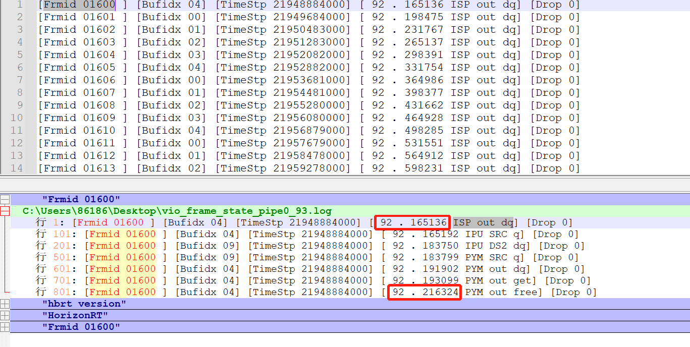
After step 2, the dumped information vio_frame_state_pipe[pipeline]_[time].log will be generated in the /userdata/log/usr/ directory.
-
Use Notepad++, search for Frmid xxxxx, where xxxxx is the frame number. The processing time of each module can be obtained by subtracting the xxx time before PYM out free from the xxx time before ISP out dq.
Method 2
By using the HB_VPS_GetChnFrame(int VpsGrp, int VpsChn, void *videoFrame, int ms) interface, the pyramid videoFrame can be obtained. The structure pointer is forcibly converted to a pym_buffer_t pointer, and then the pym_img_info can be found through pym_buffer_t. The pym_img_info contains a struct timeval tv, which is the system time filled in by sif's frame start. By using the gettimeofday interface to get the current system time minus the tv time, the delay in obtaining data from sif's frame start to pym can be obtained.