7.3.5 ISP Image System
Overview
AE
The AE algorithm operates by analyzing the histogram to calculate the new exposure value (EV) relative to the AE target set in the calibration. The AE target is dynamically controlled by the algorithm to ensure correct exposure for both low dynamic range (LDR) and high dynamic range (HDR) scenes. For example, in LDR scenes, the AE target will be based on AE_LDR_Target (18% gray target). For HDR scenes, the algorithm dynamically modifies the AE target to prevent overexposure in highlight areas. The local tone mapping engine (Iridix) ensures that shadows are displayed and properly exposed. The HDR target value needs to be calibrated based on the dynamic range of the sensor, and the Iridix engine is used to restore the content in the low-illuminated areas.
Important Concepts
Exposure Time: The time taken for the image sensor to accumulate charge internally, which is the time from the start of exposure until the charge is read out, determining the duration of light exposure for the sensor. The exposure time can be measured in terms of line length.
Exposure Gain: The total amplification factor for the output charge of the sensor, which can be either digital or analog gain. Analog gain introduces slightly less noise, so analog gain is generally preferred.
Basic Principles
The AE algorithm calculates the new EV value by analyzing the histogram statistics and combining it with the calibrated AE target value. To ensure accurate exposure in both low dynamic range and high dynamic range scenes, the algorithm dynamically adjusts the AE target value.
AWB
The AWB module is responsible for color stability because the image sensor's response to neutral tones depends on the lighting conditions of the scene and does not possess the color constancy under different lighting color temperatures as perceived by the human eye, making it particularly apparent in neutral tones such as white and gray. Therefore, the white balance module needs to restore the colors of objects that appear white to the human eye, so that they are also displayed as white in the photos. The AWB algorithm handles a wide range of lighting conditions and spectra to avoid undesirable color casts.
Important Concepts
Color Temperature: The spectral characteristics of the radiation light from a blackbody with a certain surface temperature.
Color Constancy: The tendency of human perception to perceive the surface color of objects as stable even when the illumination conditions change.
Basic Principles
The white balance channel correction is completed based on AWB statistical information and the algorithm's static correction results. The correction results are not updated in the frame data but are instead updated as part of the configuration in the next frame.
Demosaic
The Demosaic unit is responsible for reconstructing a full-color image from the (spatially undersampled) color samples obtained from an image sensor output covered with a color filter array (CFA). In addition, this module provides advanced control for image sharpening.
Digital camera sensor elements can only record the intensity of light falling on them and cannot distinguish between different colors, thus producing only grayscale images. To capture color information, filters must be placed on each pixel sensor, allowing only specific colors of light to pass through. The filters used must be able to reconstruct a full-color image with red, green, and blue (RGB) values for each pixel. The most common type of color filter array is known as the "Bayer array" because the filters are arranged in an RGGB pattern for every 2x2 pixel group.
Half of all pixels are green (G), and one-quarter each are red (R) and blue (B). Green cells in the same row as blue are marked as Gb, and green cells in the same row as red are marked as Gr. The pattern can start with R, Gr, Gb, or B. 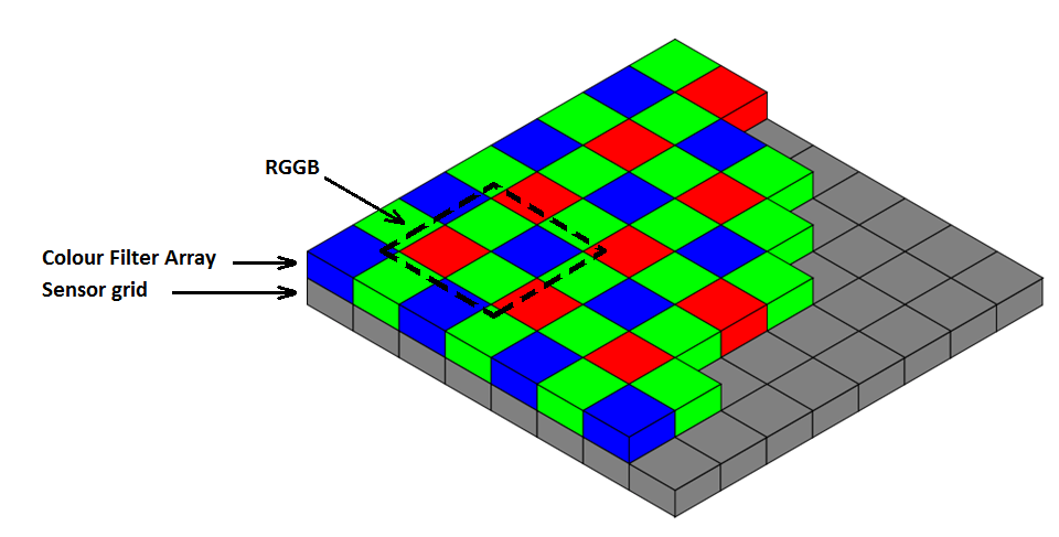
This arrangement of the color filter essentially results in undersampled color information. The demosaic unit is responsible for reconstructing a full-color image (with R, G, B information for each pixel) from this incomplete color information. 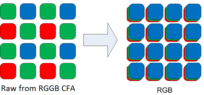 The module consists of many filters, which reconstruct the chroma channel based on the interpolated luma channel. It also takes into account the signal-related sensor noise (based on earlier determined noise profile) to maintain sharpness of edges and smoothness of regions while interpolating missing pixel components. Therefore, the interpolation of missing pixel components includes the noise of the sensor. The built-in sharpening minimizes amplification of high-frequency noise.
Sharpen
Also known as backend sharpening, this module is designed to work in synergy with the Sharpen module of the Demosaic module. The sharpening in the Demosaic module controls sharpening in the RGB domain to achieve the required resolution, but excessive sharpening can lead to artifacts and unnatural textures.
Dark areas use the configuration registers: luma thresh low and luma slope low;
Bright areas use the configuration registers: luma thresh high and luma slope high.
The following image shows the effect of these four parameters on the sharpening effect: 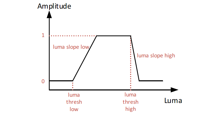
Gamma
This module encodes the output gamma and is typically set to match the BT.709 or sRGB gamma curves.
This module applies gamma LUT to each of the three (R, G, B) color channels.
In a typical configuration, the LUT consists of 129 uniformly spaced nodes labeled 0...128, and linear interpolation is applied between these nodes in hardware. 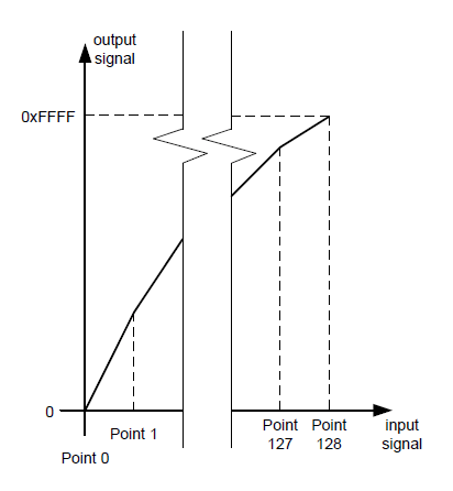
Each data value is a 16-bit unsigned integer, so it can be expected that Gamma[0] = 0 and Gamma[128] = 0xFFFF, and the other 127 values define the gamma correction curve.
Note:
Adaptive contrast enhancement is dynamically performed by the Iridix module. The LUT should be statically modified according to the desired output gamma characteristics. Gamma also affects the AE, CCM, and Iridix modules, so these modules need to be revalidated when gamma changes.
Iridix
Iridix® uses local tone mapping for dynamic range compression (DRC) to attempt to recover details from low-visibility areas in HDR scenes without affecting the global image. Overall, it increases the available tone range for local regions by increasing the gain relative to the scene content.
CNR
The CNR module corrects the color of each pixel in the YUV space by intelligently estimating the average chroma of the surrounding pixels, reducing chroma noise in the image. In this process, the module maintains the integrity of the intensity information in the image and only processes its chroma part.
Internally, this module operates in the YUV domain. It first converts the RGB image to the YUV domain, and then further subdivides it based on the color component, separately processing the U and V channels. Finally, it converts the YUV back to the RGB domain.
Note: This YUV is not directly outputted. The CNR module will convert RGB to YUV and output it to IPU or DDR.
The processing for U and V involves applying a Gaussian kernel to each U and V channel in the respective segments and configuring them with corresponding offset or slope parameters. To minimize hardware implementation or reduce the number of large kernels, vertical Gaussian filtering is replaced by emerging recursive filters.
Furthermore, to further reduce area, the color channels are downsampled before processing and upsampled again at the output stage. The output U and V channels are a blend of the processed U and V channels and the original U and V channels, configured by incremental offset or slope parameters. The processed U and V, along with the unprocessed Y, are then converted back to the RGB domain.
CCM
In most cases, standard colors may not provide the best image quality. Depending on the application or customer preference, the CCM module can correct and adjust the colors. This module alters the chromatic values of the image to match the chromatic values of a standard color space.
The module applies linear color correction to the input {R, G, B} or {R, G, B, Ir} pixel values. The coefficient matrix is calculated as follows: 
In1, In2, In3, and In4 are the inputs (corresponding to R, G, B, and Ir, respectively), and A11 to A34 are the configurable matrix coefficients. The coefficients are 13-bit values in the s4.8 fixed-point format, with the MSbit (12 bits) as the sign bit. The MSbit (12 bits) for negative values is set to 1.
Note: If the CFA pattern is RGGB, the IR coefficient and the IR channel offset must be set to zero.
Sinter
Sinter® is an advanced spatial noise reduction module that combines a set of algorithms to suppress sensor noise. The filter operates in the RAW data domain and effectively reduces the noise perceived by the human eye in the image while maintaining texture and details, resulting in more natural-looking processed images.
The module can be simplified by using an externally generated sensor Noise Profile LUT. Once the LUT table is correctly configured, the module can be controlled with a minimal set of registers. In most cases, only the Sinter:Thresh Long and Sinter:Thresh Short registers need to be modified to adjust the strength of the noise filter.
The Sinter:Thresh Long and Sinter:Thresh Short registers correspond to long exposure and short exposure, respectively, for WDR mode. When the exposure ratio is 1 or WDR mode is disabled, the Sinter:Thresh Long and Sinter:Thresh Short should be set to the same value. The thresholds are determined from images captured with various ISO values during a standard calibration process and modulated by the system gain. If the image is created using frame-switching, these values should be set accordingly based on the exposure ratio.
Temper
The Temper module is a motion-adaptive temporal noise filter. It recursively averages the current frame with previous historical frames based on the level of local motion detected in the current frame. The filter works in the RAW domain and requires two frames of external storage with a data width of video width + 4 bits.
Note: The video width is larger in WDR mode.
The recursion depth can be adjusted by increasing or decreasing the Recursion_Limit, which in turn affects the number of effective frames used for recursive averaging. Increasing this parameter will result in a smaller recursion depth, smaller denoising effect, and minimum motion artifacts.
When the Recursion_Limit is set to 0, up to 16 frames can be averaged.
When the Recursion_Limit is set to 0xf, no frames are averaged, which is equivalent to disabling Temper.
The threshold of Temper is used to adjust the strength of the Temper noise filter. The performance of this module is ensured by an externally generated sensor Noise Profile LUT. The reference data is stored in DDR through DMA, with 2 read DMAs and 2 write DMAs managing the storage of the reference data.
Mesh Shading
Due to uneven optical refraction of the lens, there can be a phenomenon of a bright center and dark surroundings in the image. Mesh shading correction provides further correction for non-linear color distortion and fine-tunes the effects caused by radial shading correction.
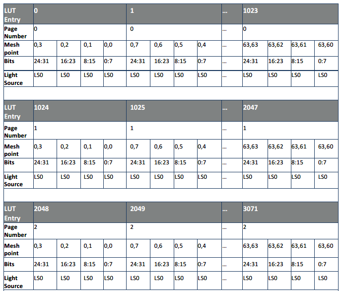
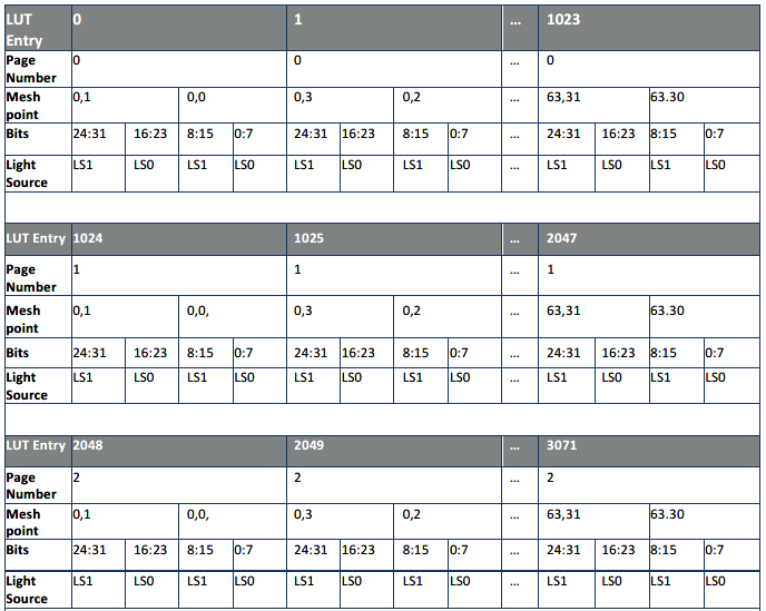
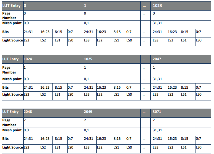
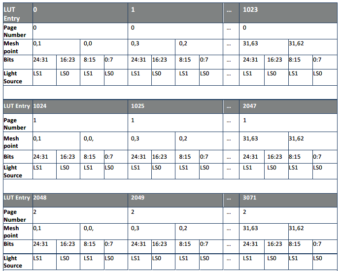
This module applies mesh shading correction to the image using a maximum 64x64 grid. The mesh correction has 3 pages (R/G/B) of correction tables and 4 different modes:
Setting Mesh Alpha Mode = 0
Setting Mesh Alpha Mode = 1
Setting Mesh Alpha Mode = 2
Setting Mesh Alpha Mode = 3
Radial Shading
Radial shading is a correction method for lens shading that corresponds to mesh shading. It corrects the effects of eccentric and elliptical shading using the radial nature of lens shading.
The radial shading coefficients are stored in a 32-bit, 4x129 entry LUT, with coefficients in x.12 format where the lower 12 bits represent the decimal portion. For each color plane, the coefficients are stored from the center to the outer edge.
Color Space Conversion
This module converts the input {R, G, B} pixel values to {Y, U, V} values using standard 3x3 matrix multiplication and vector offset. If the conversion is not activated, the ISP outputs pixel in RGB format. 
If needed, the parameters can be modified to provide different conversions. Taking BT.709 as an example, the formula is as follows: 
The corresponding parameters in the calibration for RGB2YUV_CONVERSION are as follows:
Where, if the coefficients (Coefft11, Coefft12, Coefft13, Coefft21, Coefft22, Coefft23, Coefft31, Coefft32, Coefft33) are positive, the corresponding parameters in calibration are Coefft11 * 256 rounded to the nearest integer; if the coefficients are negative, the corresponding parameters in calibration are (|Coefft11 * 256| + 1<<15) rounded to the nearest integer. The parameters in calibration for Coefft01 (Coefft02, Coefft01) are Coefft01 (Coefft02, Coefft01) * 1024 rounded to the nearest integer.
Statistical information
The 3A statistical information includes AWB, AE, and AF.
The statistical information collected by the AWB module is used for software white balance adjustment. It accumulates area-level R/G and B/G statistical information and also collects frame-level statistical information.
The AE automatic exposure statistical information is used to adjust sensor exposure. This is done by collecting 5-bin and 1024-bin histograms.
The AF module calculates the statistical sharpness value in the image. Software uses this value/statistical information to adjust the lens for optimal focus in the region of interest (ROI). This module computes edge values for both the region and the entire image.
The ISP provides programmable markers for each statistical module.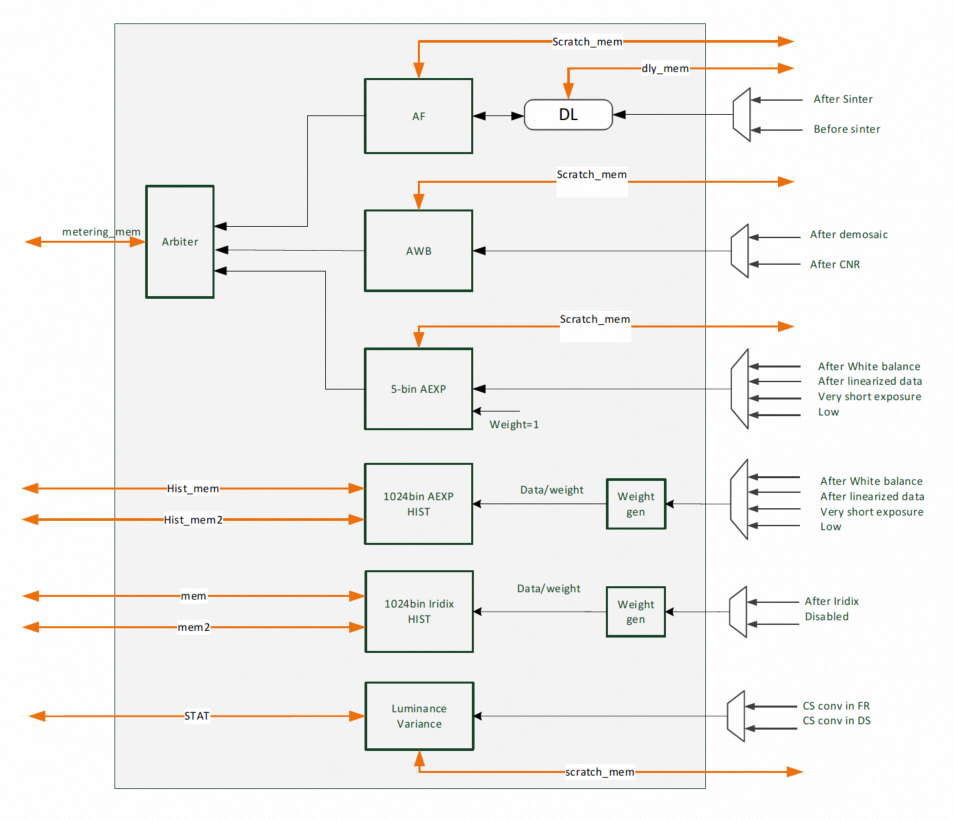
AWB Statistical Information
AWB has both global and area statistical information.
Global statistical information: the mean values of R/G and B/G for the entire image and the number of valid statistical points.
Area statistical information: supports up to 33x33 blocks in the image, with each block outputting the mean values of R/G, B/G, and the number of valid statistical points.
The AWB_stats_mode register can be used to configure the type of mean: R/G, B/G, or G/R, G/B.
Through register configuration, valid pixels can be limited:
The values Cb_Ref_Min/Max and Cr_Ref_Min/Max limit the maximum and minimum values of R/G and B/G.
Additionally, Cb_Ref_Low/High and Cr_Ref_Low/High can be used to limit a smaller range of R/G and B/G.
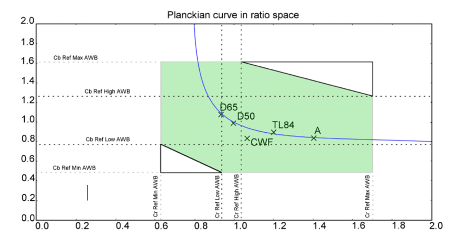
Global statistical information is stored in three registers: AWB RG, AWB BG, and SUM.
Area statistical information: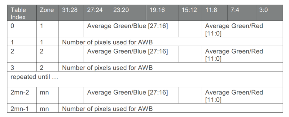
AE Statistical Information
Automatic exposure (AE) statistical information is collected after applying black level, white balance, and ISP gain. It includes two types of histograms:5-bin local and global histograms;
1024-bin global histogram;
5-bin histogram
Using adjustable histogram bin boundaries, generate a 5-bin normalized histogram for each region and the entire image. Statistics_Hist_Thresh[i][j] is used to define the intensity threshold between bin i and bin j.
Statistics_Hist[i] provides the globally normalized pixel count for bin i, with the sum normalized to 0xFFFF.
The histogram that does not provide the intermediate bins but can be calculated by software: 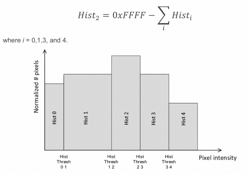
The internal table containing Histx data provides the normalized values of the histogram for each region, as shown in the table below for mxn regions. The order of the regions is the raster order starting from the top left corner of the image. For each region, the sum of the histogram data is normalized to 0xFFFF.
Supports up to
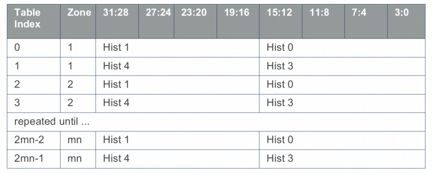
33x33 blocks.
1024-bin histogram
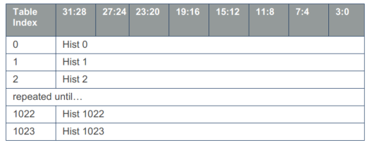
Construct a global 1024-bin histogram for the entire image. The global histogram can be weighted for regions but is not normalized. ISP Firmware performs the normalization of the statistical data. 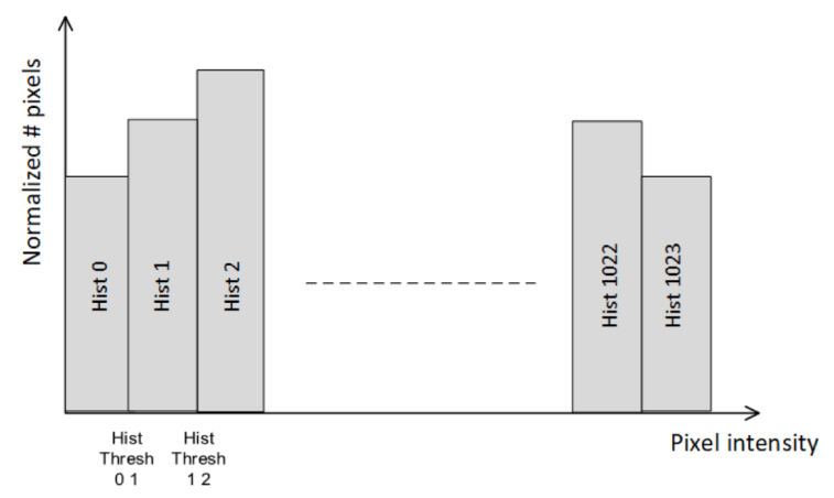
AF statistics
Automatic focus (AF) statistics consist of the region of interest (ROI) or region-based, normalized contrast indicators of the entire image. The CPU uses this contrast measure to determine the position of the lens for optimal focusing.
The sharpness evaluation function of the AF statistics module calculates the contrast in four directions of each pixel, as shown in the following figure: 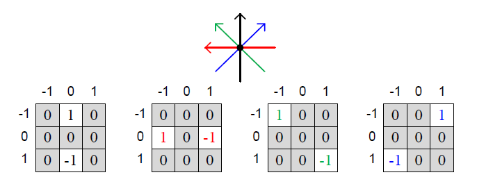
It should be noted that the AF statistics module does not support modifying the coefficients of the sharpness evaluation function. Users can modify the kernel to change the pixel position for sharpness calculation to adapt to different scenes. The sharpness calculation under different kernels of the AF statistics module is shown in the following figure. 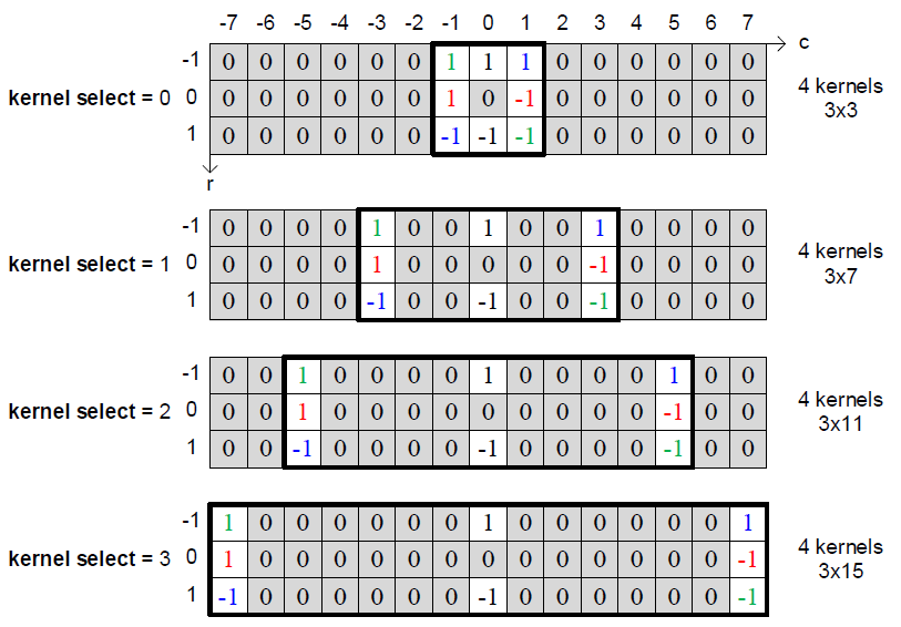
For the AF module, the regions can be configured by software. The module calculates the contrast measure for each pixel in the region and accumulates it over the entire region. For each pixel, the contrast is calculated along the four directions. In addition, kernel selection configuration parameters can be used to control the angular direction of the diagonals, as shown in the table above. To improve the response under low light and low-pass imaging conditions, the calculated contrast is in four levels (sum of four contrasts).
These region measure standards are not weighted in the hardware, but the software can apply region-based weights after calculation.
The following figure shows that the best focusing can be achieved when the AF contrast indicator reaches its maximum point: 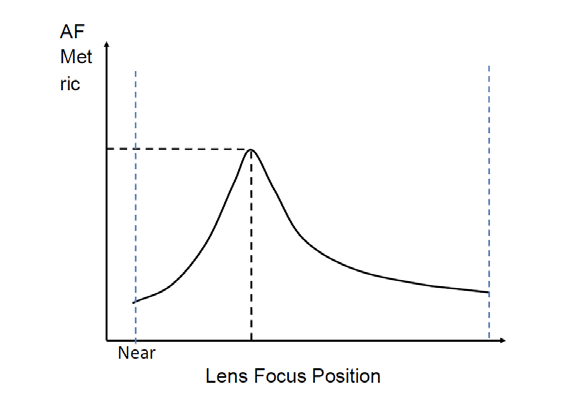
AF measure data calculation
The accumulated contrast measure standards for each region are stored in a floating-point format with 16-bit mantissa and 5-bit exponent. In addition to the contrast indicator, we also accumulate the squared image and fourth power image data in that region, as shown in the following figures. The value I2 refers to the sum of squares of the differences between the pixel values in the four directions shown in Figure 1, and I4 refers to the sum of fourth powers of the differences between the pixel values in the four directions in Figure 1. E4 refers to the accumulation of the fourth powers of the pixel differences under four kernels, as shown in Figure 2. The 16-bit mantissa stores the mantissa, and the 5-bit exponent stores the exponent. Register1 and Register2 are combined to form a 64-bit value. Users do not need to calculate it directly but can directly obtain the cv value using HB_ISP_GetMeteringData.
The statistical information accumulated for each region is shown in the following table: 
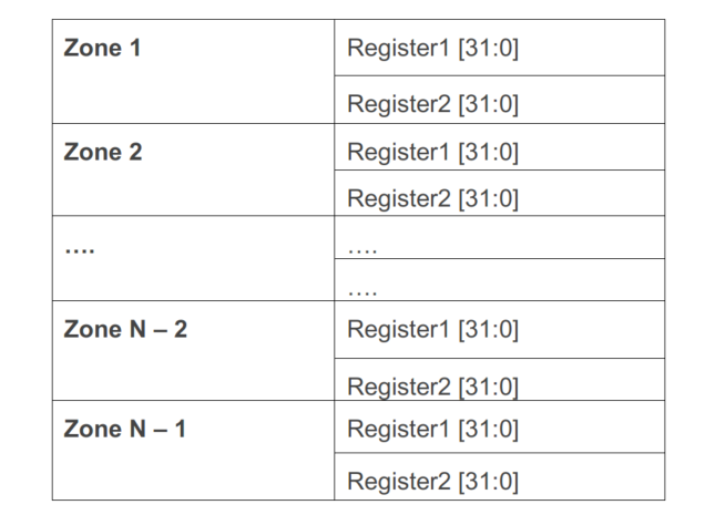
The AF region data is stored in the following format:
In addition to the region statistics, AF also accumulates the normalized fourth edge sum, which is stored in a 32-bit register.
Auto Level Statistics
1024-bin statistics data provided by the iridix module. 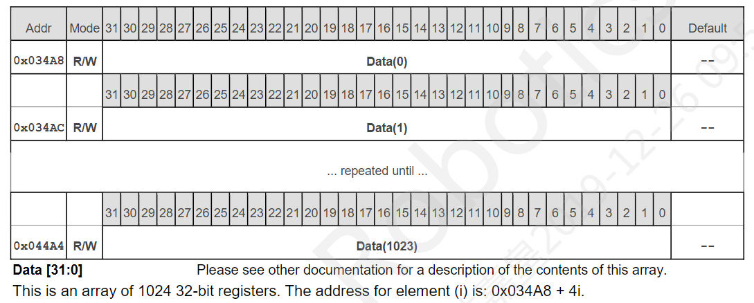
Average Brightness and Variance Statistics
Statistics information on the average brightness of the YUV domain and the variance of the average brightness provided by the ISP. This module always uses a fixed region size of 32x16 (horizontal x vertical), and the minimum frame resolution required for the available results from this statistical module is 512x256. These statistics are stored in the SRAM at 512 locations, with each location containing the 10-bit (LSB) average value information and 12-bit (MSB) variance information of the average brightness for each region. The storage format is 10 bits reserved + 12 bits brightness variance + 10 bits average brightness.
Functional Description
Interactive Data
Algorithm Library and ISP Firmware Interaction Diagram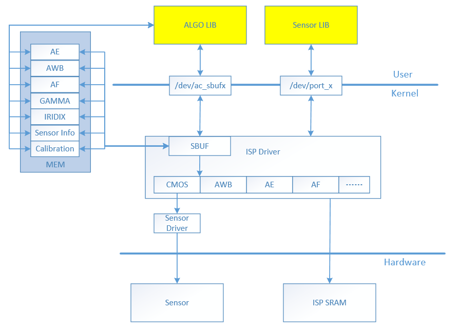
The contents in MEM are divided into two parts: data provided to the algorithm library and values passed from the algorithm library to the ISP driver. If the AWB in the ISP driver receives values from algorithm configuration, it will update the ISP register space.
-
This is the context (corresponding to a sensor), and there are multiple sets of data structures for multiple sensors.
-
The yellow blocks are replaceable parts, the Algo Lib needs several callback interfaces (see "API Reference" section), and also requires some input and output data (see "Data Structures" section).
-
The Sensor Driver includes commonly used sensor gain and exposure configuration methods, which generally do not need to be modified.
Interaction Data between Algorithm Library and ISP Firmware
| Module | ISP Fw -> Algorithm Library | Algorithm Library -> ISP Fw |
|---|---|---|
| AE | stats_data[ISP_FULL_HISTOGRAM_SIZE] | ae_exposure |
| histogram_sum | ae_exposure_ratio | |
| hist4[33 * 33] | frame_id | |
| AWB | stats_data[MAX_AWB_ZONES] | awb_red_gain |
| curr_AWB_ZONES | awb_green_even_gain | |
| awb_green_odd_gain | ||
| awb_blue_gain | ||
| temperature_detected | ||
| p_high | ||
| light_source_candidate | ||
| awb_warming[3] | ||
| mix_light_contrast | ||
| frame_id | ||
| AF | stats_data[AF_ZONES_COUNT_MAX][2] | frame_to_skip |
| zones_horiz | af_position | |
| zones_vert | af_last_sharp | |
| frame_num | ||
| skip_cur_frame | ||
| zoom_step_info | ||
| Gamma | stats_data[ISP_FULL_HISTOGRAM_SIZE] | gamma_gain |
| frame_id | ||
| Iridix | N/A(using AE statistics data from AE algorithm) | strength_target |
| iridix_dark_enh | ||
| iridix_global_DG | ||
| iridix_contrast | ||
| frame_id |
Development Notes
ISP Firmware consists of two parts, the user space and the kernel space. The kernel space Firmware initializes with the system startup, while the user space Firmware (including the default 3A algorithm) is started by the HB_VIN_StartPipe interface. During the Firmware startup process, the external 3A algorithm is chosen as a priority. If there is no registered external 3A algorithm, the default 3A algorithm will be used. Each type of algorithm has two corresponding input parameters - statistical data (stats) and input parameters (input), and one output parameter - output parameters (output). After the statistical data for each frame is ready, the ISP Firmware calls the proc_func callback function and passes in the two input parameters. The proc_func is the actual algorithm implementation, and after the algorithm calculation, the output parameters should be filled. The ISP Firmware will then apply the output parameters to the Sensor or ISP hardware.
AE Algorithm Registration
AE registers the callback function with the ISP Firmware:
| From | User Implementation | To |
|---|---|---|
| AELIB | init_func | ISP Firmware |
| proc_func | ||
| deinit_func |
Interface Description:
| Callback Function | Description |
|---|---|
| init_func | Algorithm initialization function |
| proc_func | Actual algorithm implementation, such as target and exposure calculation. Called by ISP Firmware when the AE statistical data for each frame is ready. The proc_func passes the input parameters and the parameters to be passed out. See Structural Description for details. |
| deinit_func | Algorithm deinitialization function |
AWB Algorithm Registration
AWB registers the callback function with the ISP Firmware:
| From | User Implementation | To |
|---|---|---|
| AWBLIB | init_func | ISP Firmware |
| proc_func | ||
| deinit_func |
Interface Description:
| Callback Function | Description |
|---|---|
| init_func | Algorithm initialization function |
| proc_func | Actual algorithm implementation. Called by ISP Firmware when the AWB statistical data for each frame is ready. The proc_func passes the input parameters and the parameters to be passed out. See Structural Description for details. |
| deinit_func | Algorithm deinitialization function |
AF Algorithm Registration
AF registers callback functions to ISP Firmware:
| From | User implementation | To |
|---|---|---|
| AFLIB | init_func | ISP Firmware |
| proc_func | ||
| deinit_func |
Interface description:
| Callback function | Description |
|---|---|
| init_func | Algorithm initialization function |
| proc_func | Actual algorithm implementation, called by ISP Firmware when AF statistics data is ready for each frame. See structure description for input and output parameters |
| deinit_func | Algorithm de-initialization function |
Example of algorithm registration
Taking AWB algorithm as an example:
ISP_AWB_FUNC_S stAwbFunc = {

        .init_func = awb_init_func,

        .proc_func = awb_proc_func,

        .deinit_func = awb_deinit_func,

};

HB_ISP_AWBLibRegCallback(0, "libawb.so", &stAwbFunc);

void *awb_init_func(uint32_t ctx_id)

{

        pr_info("ctx id is %d", ctx_id);

        return NULL;

}

int32_t awb_proc_func(void *awb_ctx, awb_stats_data_t *stats, awb_input_data_t *input, awb_output_data_t *output)

{
        awb_acamera_core_obj_t *p_awb_core_obj = (awb_acamera_core_obj_t *)awb_ctx;awb_acamera_input_t *p_acamera_input = (awb_acamera_input_t *)input->acamera_input;

awb_calibration_data_t *p_cali_data = &( p_acamera_input->cali_data );

awb_acamera_output_t *p_acamera_output = (awb_acamera_output_t *)output->acamera_output;

// Specific algorithm implementation, input and statistical data are passed for calculation

awb_calc_avg_weighted_gr_gb_mesh( p_awb_core_obj, stats, input );

awb_detect_light_source( p_awb_core_obj );

awb_calculate_warming_effect( p_awb_core_obj, p_cali_data );

// Assign calculation results to output parameters

p_acamera_output->rg_coef = p_awb_core_obj->rg_coef;

p_acamera_output->bg_coef = p_awb_core_obj->bg_coef;

p_acamera_output->temperature_detected = p_awb_core_obj->temperature_detected;

p_acamera_output->p_high = p_awb_core_obj->p_high;

p_acamera_output->light_source_candidate = p_awb_core_obj->light_source_candidate;

memcpy( p_acamera_output->awb_warming, p_awb_core_obj->awb_warming, sizeof( p_acamera_output->awb_warming ) );

p_acamera_output->awb_converged = p_awb_core_obj->awb_converged;

return 0;

}

int32_t awb_deinit_func(void *awb_ctx)

{

pr_info("done");

return 0;

}
API Reference
HB_ISP_SetFWState/HB_ISP_GetFWState【Function Declaration】
int HB_ISP_SetFWState(uint8_t pipeId, const ISP_FW_STATE_E enState);

int HB_ISP_GetFWState(uint8_t pipeId, ISP_FW_STATE_E *penState);
【Function Description】
Set/Get the state of ISP Firmware.
【Parameter Description】
| Parameter Name | Description | Input/Output |
|---|---|---|
| pipeId | Pipeline index number | Input |
| penState | ISP Firmware state | Input |
【Return Value】
| Return Value | Description |
|---|---|
| 0 | Success |
| Non-zero | Failure |
【Notes】
【Reference Code】
HB_ISP_SetRegister/HB_ISP_GetRegister
【Function Declaration】
int HB_ISP_SetRegister(uint8_t pipeId, uint32_t u32Addr, uint32_t u32Value);

int HB_ISP_GetRegister(uint8_t pipeId, uint32_t u32Addr, uint32_t *pu32Value);
【Function Description】
Set/Get ISP register.
【Parameter Description】
| Parameter Name | Description | Input/Output |
|---|---|---|
| pipeId | Pipeline index number | Input |
| u32Addr | ISP register address | Input |
| u32Value | Value to set | Input |
【Return Value】| Parameter name | Description | Input/Output | |----------------|---------------------------------|--------------| | pipeId | Pipeline index number | Input | | cname | Calibration library information | Input |
【Return value】
| Return value | Description |
|---|---|
| 0 | Success |
| Non-zero | Failure |
【Important points】
【Reference code】
HB_ISP_SetModuleControl/ HB_ISP_GetModuleControl
【Function declaration】
int HB_ISP_SetModuleControl(uint8_t pipeId, const ISP_MODULE_CTRL_U *punModCtrl);

int HB_ISP_GetModuleControl(uint8_t pipeId, ISP_MODULE_CTRL_U *punModCtrl);
【Function description】
Set/get the bypass status of each module inside ISP.
【Parameter description】
| Parameter name | Description | Input/Output |
|---|---|---|
| pipeId | Pipeline index number | Input |
| punModCtrl | Bypass control of each module inside ISP | Input |
【Return value】
| Return value | Description |
|---|---|
| 0 | Success |
| Non-zero | Failure |
【Important points】
【Reference code】
HB_ISP_SwitchScence
【Function declaration】
int HB_ISP_SwitchScence(uint8_t pipeId, const char *cname);
【Function description】
Set calibration library.
【Parameter description】| Parameter | Description | Input/Output | |------------|---------------------|--------------| | pipeId | Pipeline index number | Input | | cname | Calibration library path | Input |
【Return Value】
| Return Value | Description |
|---|---|
| 0 | Success |
| Non-zero | Failure |
【Notes】
【Reference Code】
HB_ISP_StartI2CBus/HB_ISP_StopI2CBus
【Function Declaration】
int HB_ISP_StartI2CBus(uint8_t pipeId);

void HB_ISP_StopI2CBus(uint8_t pipeId);
【Function Description】
Starts, stops writing to I2C bus.
【Parameter Description】
| Parameter | Description | Input/Output |
|---|---|---|
| pipeId | Pipeline index number | Input |
【Return Value】
| Return Value | Description |
|---|---|
| 0 | Success |
| Non-zero | Failure |
【Notes�】Before StartI2CBus, HB_ISP_GetSetInit initialization and sensor initialization are required.
【Reference Code】
HB_ISP_SendI2CData
【Function Declaration】
int HB_ISP_SendI2CData(ISP_I2C_DATA_S data);
【Function Description】
Write I2C data.
【Parameter Description】
| Parameter Name | Description | Input/Output |
|---|---|---|
| data | data to be sent | Input |
【Return Value】
| Return Value | Description |
|---|---|
| 0 | Success |
| Non-zero | Failure |
【Note】
HB_ISP_StartI2CBus interface should be called before using it to start the I2C write thread.
【Reference Code】
HB_ISP_AELibRegCallback
【Function Declaration】
int HB_ISP_AELibRegCallback(uint8_t pipeId, char *name, ISP_AE_FUNC_S *pstAeFunc);
【Function Description】
Register AE algorithm library.
【Parameter Description】
| Parameter Name | Description | Input/Output |
|---|---|---|
| pipeId | Pipeline index number | Input |
| name | Library name, fixed 20 chars length | Input, optional |
| pstAeFunc | AE algorithm callback function pointer | Input |
【Return Value】
| Return Value | Description |
|---|---|
| 0 | Success |
| Non-zero | Failure |
HB_VIN_StartPipe will start the ISP algorithm and the algorithm registration should be done before calling the HB_VIN_StartPipe function.
【Reference code】see [Algorithm Registration Example](#_Algorithm Registration Example)
HB_ISP_AWBLibRegCallback
【Function declaration】
int HB_ISP_AWBLibRegCallback(uint8_t pipeId, char *name,
ISP_AWB_FUNC_S *pstAWBFunc);
【Function description】
Register the AWB algorithm library.
【Parameter description】
| Parameter name | Description | Input/Output |
|---|---|---|
| pipeId | Pipeline index number | Input |
| name | Library name, fixed 20 characters | Input Reserved item, can be omitted |
| pstAWBFunc | AWB algorithm callback function pointer | Input |
【Return value】
| Return value | Description |
|---|---|
| 0 | Success |
| Non-zero | Failure |
【Caution】
HB_VIN_StartPipe will start the ISP algorithm and the algorithm registration should be done before calling the HB_VIN_StartPipe function.
【Reference code】see [Algorithm Registration Example](#_Algorithm Registration Example)
HB_ISP_AFLibRegCallback
【Function declaration】
int HB_ISP_AFLibRegCallback(uint8_t pipeId, char *name,
ISP_AF_FUNC_S *pstAFFunc);
【Function description】
Register the AF algorithm library.
【Parameter description】
| Parameter Name | Description | Input/Output |
|---|---|---|
| pipeId | Pipeline index number | Input |
| name | Library name, fixed-copy 20 characters long | Input |
| pstAFFunc | AF algorithm callback function pointer | Input |
【Return value】
| Return Value | Description |
|---|---|
| 0 | Success |
| Non-zero | Failure |
【Caution】
HB_VIN_StartPipe will start the ISP algorithm, and algorithm registration needs to be done before calling HB_VIN_StartPipe function.
【Reference code】
See [Algorithm Registration Example](#_Algorithm Registration Example)
HB_ISP_AELibUnRegCallback
【Function Declaration】
int HB_ISP_AELibUnRegCallback(uint8_t pipeId);
【Description】
Unregister AE algorithm library.
【Description】
| Parameter Name | Description | Input/Output |
|---|---|---|
| pipeId | Pipeline index number | Input |
【Return Value】
| Return Value | Description |
|---|---|
| 0 | Success |
| Non-zero | Failure |
【Caution】
【Reference code】
HB_ISP_AWBLibUnRegCallback
【Function Declaration】
int HB_ISP_AWBLibUnRegCallback(uint8_t pipeId);
【Description】
Unregister the AWB algorithm library.
【Parameter Description】
| Parameter Name | Description | Input/Output |
|---|---|---|
| pipeId | Pipeline index number | Input |
【Return Value】
| Return Value | Description |
|---|---|
| 0 | Success |
| Non-zero | Failure |
【Notes】
【Reference Code】
HB_ISP_AFLibUnRegCallback
【Function Declaration】
int HB_ISP_AFLibUnRegCallback(uint8_t pipeId);
【Description】
Unregister the AF algorithm library.
【Parameter Description】
| Parameter Name | Description | Input/Output |
|---|---|---|
| pipeId | Pipeline index number | Input |
【Return Value】
| Return Value | Description |
|---|---|
| 0 | Success |
| Non-zero | Failure |
【Notes】
【Reference Code】
Note:
-
If using the default 3A algorithm, there is no need to concern yourself with the interfaces in this chapter.
-
Zoom and aperture control algorithms are not included. Users can implement their own and provide output parameters to modify the ISP (Image Signal Processor) firmware for adaptation.
HB_ISP_GetSetInit/HB_ISP_GetSetExit
【Function Declaration】
int HB_ISP_GetSetInit(void);

int HB_ISP_GetSetExit(void);
【Description】
Initialization before getting/setting parameters.
【Parameter Description】None
【Return Value】
| Return Value | Description |
|---|---|
| 0 | Success |
| Non-zero | Failure |
【Notes】
Only need to call once in the same process, before calling all Get/Set functions, first call HB_ISP_GetSetInit for initialization.
【Reference Code】
HB_ISP_SetAeAttr/HB_ISP_GetAeAttr
【Function Declaration】
int HB_ISP_SetAeAttr(uint8_t pipeId, const ISP_AE_ATTR_S *pstAeAttr);

int HB_ISP_GetAeAttr(uint8_t pipeId, ISP_AE_ATTR_S *pstAeAttr);
【Description】
Set AE algorithm attributes.
【Parameter Description】| Parameter Name | Description | Input/Output | |----------------|------------------|--------------| | pipeId | Pipeline index | Input | | pstAeAttr | Pointer to AE parameters | Input |
【Return Value】
| Return Value | Description |
|---|---|
| 0 | Success |
| Non-zero | Failure |
【Notes】
set is only for manual mode, when getting different modes, pass the corresponding mode value.
【Reference Code】
HB_ISP_SetAfAttr/HB_ISP_GetAfAttr
【Function Declaration】
int HB_ISP_SetAfAttr(uint8_t pipeId, ISP_AF_ATTR_S *pstAfAttr);

int HB_ISP_GetAfAttr(uint8_t pipeId, ISP_AF_ATTR_S *pstAfAttr);
【Function Description】
Set AF-ZOOM attribute.
【Parameter Description】
| Parameter Name | Description | Input/Output |
|---|---|---|
| pipeId | Pipeline index | Input |
| pstAfAttr | Pointer to AF parameters | Input |
【Return Value】
| Return Value | Description |
|---|---|
| 0 | Success |
| Non-zero | Failure |
【Notes】
【Reference Code】
HB_ISP_SetAwbAttr/HB_ISP_GetAwbAttr【Function Declaration】
int HB_ISP_SetAwbAttr(uint8_t pipeId, const ISP_AWB_ATTR_S *pstAwbAttr);

int HB_ISP_GetAwbAttr(uint8_t pipeId, ISP_AWB_ATTR_S *pstAwbAttr);
【Description】
Set AWB algorithm attributes.
【Parameter Description】
| Parameter Name | Description | Input/Output |
|---|---|---|
| pipeId | Pipeline index number | Input |
| pstAwbAttr | Pointer to AWB parameters | Input |
【Return Value】
| Return Value | Description |
|---|---|
| 0 | Success |
| Non-zero | Failure |
【Notes】
Set is only for manual mode. When getting, pass different modes to obtain corresponding values.
【Referenced Code】
HB_ISP_SetBlackLevelAttr/HB_ISP_GetBlackLevelAttr
【Function Declaration】
int HB_ISP_SetBlackLevelAttr(uint8_t pipeId, const ISP_BLACK_LEVEL_ATTR_S *pstBlackLevelAttr);

int HB_ISP_GetBlackLevelAttr(uint8_t pipeId, ISP_BLACK_LEVEL_ATTR_S *pstBlackLevelAttr);
【Description】
Set black level attributes.
【Parameter Description】
| Parameter Name | Description | Input/Output |
|---|---|---|
| pipeId | Pipeline index number | Input |
| pstBlackLevelAttr | Pointer to black level parameter | Input |
| [Return Values] |
| Return Value | Description |
|---|---|
| 0 | Success |
| Non-zero | Failure |
[Note]
Set is only applicable to manual mode. When getting, different modes can be passed to obtain the corresponding values.
In auto mode, the black_level value is interpolated based on the current exposure gain using calibration parameters BLACK_LEVEL_B/BLACK_LEVEL_GB/BLACK_LEVEL_GR/BLACK_LEVEL_R.
In manual mode, the black_level value can be set by the user.
[Reference Code]
HB_ISP_SetDemosaicAttr/HB_ISP_GetDemosaicAttr
[Function Declaration]
int HB_ISP_SetDemosaicAttr(uint8_t pipeId, const
ISP_DEMOSAIC_ATTR_S *pstDemosaicAttr);

int HB_ISP_GetDemosaicAttr(uint8_t pipeId,
ISP_DEMOSAIC_ATTR_S *pstDemosaicAttr);
[Functional Description]
Set demosaic module attributes.
[Parameter Description]
| Parameter Name | Description | Input/Output |
|---|---|---|
| pipeId | Pipeline index number | Input |
| pstDemosaicAttr | Pointer to demosaic parameters | Input |
[Return Values]
| Return Value | Description |
|---|---|
| 0 | Success |
| Non-zero | Failure |
[Note]
HB_ISP_SetSharpenAttr/HB_ISP_GetSharpenAttr
【Function declaration】
int HB_ISP_SetSharpenAttr(uint8_t pipeId, const
ISP_SHARPEN_ATTR_S *pstSharpenAttr);

int HB_ISP_GetSharpenAttr(uint8_t pipeId,
ISP_SHARPEN_ATTR_S *pstSharpenAttr);
【Description】
Set the sharpen attribute.
【Parameter description】
| Parameter name | Description | Input/Output |
|---|---|---|
| pipeId | Pipeline index | Input |
| pstSharpenAttr | Pointer to sharpen attribute | Input |
【Return value】
| Return value | Description |
|---|---|
| 0 | Success |
| Non-zero | Failure |
【Notes】
【Reference code】
HB_ISP_SetGammaAttr/HB_ISP_GetGammaAttr
【Function declaration】
int HB_ISP_SetGammaAttr(uint8_t pipeId, const
ISP_GAMMA_ATTR_S *pstGammaAttr);

int HB_ISP_GetGammaAttr(uint8_t pipeId,
ISP_GAMMA_ATTR_S *pstGammaAttr);
【Description】
Set the gamma attribute.
【Parameter description】| Parameter Name | Description | Input/Output | |--------------|---------------------|-----------| | pipeId | Pipeline Index | Input | | pstGammaAttr | Pointer to Gamma Parameters | Input |
【Return Value】
| Return Value | Description |
|---|---|
| 0 | Success |
| Non-zero | Failure |
【Note】
【Reference Code】
HB_ISP_SetIridixAttr/HB_ISP_GetIridixAttr
【Function Declaration】
int HB_ISP_SetIridixAttr(uint8_t pipeId, const ISP_IRIDIX_ATTR_S *pstIridixAttr);

int HB_ISP_GetIridixAttr(uint8_t pipeId,
ISP_IRIDIX_ATTR_S *pstIridixAttr);
【Function Description】
Set Iridix module attributes.
【Parameter Description】
| Parameter Name | Description | Input/Output |
|---|---|---|
| pipeId | Pipeline Index | Input |
| pstIridixAttr | Pointer to Iridix Parameters | Input |
【Return Value】
| Return Value | Description |
|---|---|
| 0 | Success |
| Non-zero | Failure |
【Note】
【Reference Code】
HB_ISP_SetIridixStrengthLevel/HB_ISP_GetIridixStrengthLevel
【Function Declaration】
int HB_ISP_SetIridixStrengthLevel(uint8_t pipeId, uint16_t level);

int HB_ISP_GetIridixStrengthLevel(uint8_t pipeId, uint16_t *level);
【Function Description】
Set the Iridix strength level.
【Parameter Description】
| Parameter Name | Description | Input/Output |
|---|---|---|
| pipeId | Pipeline index number | Input |
| level | Strength level, range [0, 255] | Input |
【Return Value】
| Return Value | Description |
|---|---|
| 0 | Success |
| non-zero | Failure |
【Note】
【Reference Code】
HB_ISP_SetCnrAttr/HB_ISP_GetCnrAttr
【Function Declaration】
int HB_ISP_SetCnrAttr(uint8_t pipeId, const ISP_CNR_ATTR_S *pstCnrAttr);

int HB_ISP_GetCnrAttr(uint8_t pipeId, ISP_CNR_ATTR_S *pstCnrAttr);
【Function Description】
Set the chroma noise reduction module attributes.
【Parameter Description】
| Parameter Name | Description | Input/Output |
|---|---|---|
| pipeId | Pipeline index number | Input |
| pstCnrAttr | Pointer to chroma noise reduction parameters | Input |
【Return Value】
| Return Value | Description |
|---|---|
| 0 | Success |
| Non-zero | Failure |
【Notes】
【Reference Code】
HB_ISP_SetSinterAttr/HB_ISP_GetSinterAttr
【Function Declaration】
int HB_ISP_SetSinterAttr(uint8_t pipeId, const ISP_SINTER_ATTR_S *pstSinterAttr);

int HB_ISP_GetSinterAttr(uint8_t pipeId,
ISP_SINTER_ATTR_S *pstSinterAttr);
【Function Description】
Set the attributes of the spatial noise reduction module.
【Parameter Description】
| Parameter Name | Description | Input/Output |
|---|---|---|
| pipeId | Pipeline index number | Input |
| pstSinterAttr | Pointer to the spatial noise reduction parameter | Input |
【Return Value】
| Return Value | Description |
|---|---|
| 0 | Success |
| Non-zero | Failure |
【Notes】
【Reference Code】
HB_ISP_SetTemperAttr/HB_ISP_GetTemperAttr
【Function Declaration】
int HB_ISP_SetTemperAttr(uint8_t pipeId, const
ISP_TEMPER_ATTR_S *pstTemperAttr);

int HB_ISP_GetTemperAttr(uint8_t pipeId,
ISP_TEMPER_ATTR_S *pstTemperAttr);
【Function Description】【Setting the temporal domain denoising module properties】
【Parameter description】
| Parameter Name | Description | Input/Output |
|---|---|---|
| pipeId | Pipeline index number | Input |
| pstTemperAttr | Pointer to denoising parameters in the temporal domain | Input |
【Return value】
| Return value | Description |
|---|---|
| 0 | Success |
| Non-zero | Failure |
【Notes】
【Reference code】
HB_ISP_SetMeshShadingAttr/HB_ISP_GetMeshShadingAttr
【Function declaration】
int HB_ISP_SetMeshShadingAttr(uint8_t pipeId, const
MESH_SHADING_ATTR_S *pstMeshShadingAttr);

int HB_ISP_GetMeshShadingAttr(uint8_t pipeId,
MESH_SHADING_ATTR_S *pstMeshShadingAttr);
【Function description】
Set the properties of the Mesh Shading module.
【Parameter description】
| Parameter Name | Description | Input/Output |
|---|---|---|
| pipeId | Pipeline index number | Input |
| pstMeshShadingAttr | Pointer to Mesh Shading parameters | Input |
【Return value】
| Return value | Description |
|---|---|
| 0 | Success |
| Non-zero | Failure |
【Notes】
HB_ISP_SetMeshShadingLUT/HB_ISP_GetMeshShadingLUT
【Function Declaration】
int HB_ISP_SetMeshShadingLUT(uint8_t pipeId, const
MESH_SHADING_LUT_S *pstMeshShadingLUT);

int HB_ISP_GetMeshShadingLUT(uint8_t pipeId, MESH_SHADING_LUT_S *pstMeshShadingLUT);
【Function Description】
Set the LUT table of the Mesh Shading module.
【Parameter Description】
| Parameter Name | Description | Input/Output |
|---|---|---|
| pipeId | Pipeline index number | Input |
| pstMeshShadingLUT | Pointer to the MeshShading LUT table | Input |
【Return Value】
| Return Value | Description |
|---|---|
| 0 | Success |
| Non-zero | Failure |
【Notes】
【Reference Code】
HB_ISP_SetRadialShadingAttr/HB_ISP_GetRadialShadingAttr
【Function Declaration】
int HB_ISP_SetRadialShadingAttr(uint8_t pipeId, const
RADIAL_SHADING_ATTR_S *pstRadialShadingAttr);

int HB_ISP_GetRadialShadingAttr(uint8_t pipeId,
RADIAL_SHADING_ATTR_S *pstRadialShadingAttr);
【Function Description】
Set the attributes of the Radial Shading module.
【Parameter Description】
| Parameter Name | Description | Input/Output |
|---|---|---|
| pipeId | Pipeline index | Input |
| pstRadialShadingAttr | Pointer to Radial Shading parameters | Input |
【Return Value】
| Return Value | Description |
|---|---|
| 0 | Success |
| Non-zero | Failure |
【Notes】
【Reference Code】
HB_ISP_SetRadialShadingLUT/HB_ISP_GetRadialShadingLUT
【Function Declaration】
int HB_ISP_SetRadialShadingLUT(uint8_t pipeId, const
RADIAL_SHADING_LUT_S *pstRadialShadingLUT);

int HB_ISP_GetRadialShadingLUT(uint8_t pipeId,
RADIAL_SHADING_LUT_S *pstRadialShadingLUT);
【Function Description】
Set the LUT table for Radial Shading module.
【Parameter Description】
| Parameter Name | Description | Input/Output |
|---|---|---|
| pipeId | Pipeline index | Input |
| pstRadialShadingLUT | Pointer to Radial Shading LUT table | Input |
【Return Value】
| Return Value | Description |
|---|---|
| 0 | Success |
| Non-zero | Failure |
【Notes】
【Reference Code】
HB_ISP_SetCSCAttr/HB_ISP_GetCSCAttr
【Function Declaration】
int HB_ISP_SetCSCAttr(uint8_t pipeId, const ISP_CSC_ATTR_S *pstCSCAttr);

int HB_ISP_GetCSCAttr(uint8_t pipeId, ISP_CSC_ATTR_S *pstCSCAttr);
【Function Description】
Set the attributes of the Color Space Conversion (CSC) module.
【Parameter Description】
| Parameter Name | Description | Input/Output |
|---|---|---|
| pipeId | Pipeline index | Input |
| pstCSCAttr | Pointer to CSC attributes | Input |
【Return Value】
| Return Value | Description |
|---|---|
| 0 | Success |
| Non-zero | Failure |
【Notes】
【Reference Code】
HB_ISP_SetSceneModesAttr/HB_ISP_GetSceneModesAttr
【Function Declaration】
int HB_ISP_SetSceneModesAttr(uint8_t pipeId, const ISP_SCENE_MODES_ATTR_S *pstSceneModesAttr);

int HB_ISP_GetSceneModesAttr(uint8_t pipeId, ISP_SCENE_MODES_ATTR_S *pstSceneModesAttr);
【Function Description】
Set the scene modes.
【Parameter Description】
| Parameter Name | Description | Input/Output |
|---|---|---|
| pipeId | Pipeline index | Input |
| pstSceneModesAttr | Pointer to scene mode parameters | Input |
【Return Value】 Translate the Chinese parts in the following content into English while preserving the original format and content:
| Return Value | Description |
|---|---|
| 0 | Success |
| Non-zero | Failure |
【Precautions】
【Reference Code】
HB_ISP_SetAwbZoneInfo/HB_ISP_GetAwbZoneInfo
【Function Declaration】
int HB_ISP_GetAwbZoneInfo(uint8_t pipeId, ISP_ZONE_ATTR_S *awbZoneInfo);

int HB_ISP_SetAwbZoneInfo(uint8_t pipeId, ISP_ZONE_ATTR_S awbZoneInfo);
【Description】
Get/Set AWB zone information.
【Parameter Description】
| Parameter Name | Description | Input/Output |
|---|---|---|
| pipeId | Pipeline index | Input |
| awbZoneInfo | Pointer to AWB zone information (for Get); AWB zone information data structure (for Set) | Input |
【Return Value】
| Return Value | Description |
|---|---|
| 0 | Success |
| Non-zero | Failure |
【Precautions】None
【Reference Code】None
HB_ISP_SetAfZoneInfo/HB_ISP_GetAfZoneInfo
【Function Declaration】
int HB_ISP_GetAfZoneInfo(uint8_t pipeId, ISP_ZONE_ATTR_S *afZoneInfo);

int HB_ISP_SetAfZoneInfo(uint8_t pipeId, ISP_ZONE_ATTR_S *afZoneInfo);
【Description】Access/Set AF zones information.
[Parameter Description]
| Parameter Name | Description | Input/Output |
|---|---|---|
| pipeId | Pipeline index number | Input |
| afZoneInfo | Pointer to AF zones information (for getting); AF zones information data structure (for setting) | Input |
[Return Value]
| Return Value | Description |
|---|---|
| 0 | Success |
| Non-zero | Failure |
[Notes] None
[Reference Code] None
HB_ISP_SetAe5binZoneInfo/HB_ISP_GetAe5binZoneInfo
[Function Declaration]
int HB_ISP_GetAe5binZoneInfo(uint8_t pipeId,
ISP_ZONE_ATTR_S *ae5binZoneInfo);

int HB_ISP_SetAe5binZoneInfo(uint8_t pipeId,
ISP_ZONE_ATTR_S ae5binZoneInfo);
[Function Description]
Access/Set AE 5bin zones information.
[Parameter Description]
| Parameter Name | Description | Input/Output |
|---|---|---|
| pipeId | Pipeline index number | Input |
| ae5binZoneInfo | Pointer to AE 5bin zones information (for getting); AE 5BIN zones information data structure (for setting) | Input |
[Return Value]
| Return Value | Description |
|---|---|
| 0 | Success |
| Non-zero | Failure |
[Notes]
HB_ISP_SetAfKernelInfo/HB_ISP_GetAfKernelInfo
【Function Declaration】
int HB_ISP_GetAfKernelInfo(uint8_t pipeId, uint32_t *af_kernel);

int HB_ISP_SetAfKernelInfo(uint8_t pipeId, uint32_t af_kernel);
【Description】
Get/Set AF KERNEL information.
【Parameter Description】
| Parameter Name | Description | Input/Output |
|---|---|---|
| pipeId | Pipeline index number | Input |
| af_kernel | Pointer to af_kernel pointer (for getting); af_kernel data information (for setting) | Input |
【Return Value】
| Return Value | Description |
|---|---|
| 0 | Success |
| Non-zero | Failure |
【Notes】
This interface is mainly used for applications to obtain or modify current af statistical data kernel.
【Reference Code】
HB_ISP_SetAeParam/HB_ISP_GetAeParam
Function Declaration
int HB_ISP_SetAeParam(uint8_t pipeId, const ISP_AE_PARAM_S *pstAeParam);

int HB_ISP_GetAeParam(uint8_t pipeId, ISP_AE_PARAM_S *pstAeParam);
Function Description
Sets/gets AE parameter information, including line and total gain.
Parameter Descriptions
| Parameter Name | Description | Input/Output |
|---|---|---|
| pipeId | Pipeline index | Input |
| pstAeParam | Pointer to AE parameter structure | Input |
Return Values
| Return Value | Description |
|---|---|
| 0 | Success |
| Non-zero | Failure |
Cautionary Notes
Reference Code: None
HB_ISP_SetAeRoiInfo/HB_ISP_GetAeRoiInfo
Function Declaration
int HB_ISP_SetAeRoiInfo(uint8_t pipeId, ISP_AE_ROI_ATTR_S aeRoiInfo);

int HB_ISP_GetAeRoiInfo(uint8_t pipeId, ISP_AE_ROI_ATTR_S *aeRoiInfo);
Function Description
Sets the ROI (Region of Interest) weight area for AE, allowing dynamic calls.
Parameter Descriptions
| Parameter Name | Description | Input/Output |
|---|---|---|
| pipeId | Pipeline index | Input |
| aeRoiInfo | ROI attribute structure | Output |
Return Values
| Return Value | Description |
|---|---|
| 0 | Success |
| Non-zero | Failure |
Cautionary Note
The ROI region setting is independent from the 3A-AE ROI weighting setup. Only one of these functions can be used at any given time.
Reference Code: None
HB_ISP_SetAwbStatAreaAttr / HB_ISP_GetAwbStatAreaAttr
Function Declaration
int HB_ISP_GetAwbStatAreaAttr(uint8_t pipeId, ISP_AWB_STAT_AREA_ATTR_S *pstAwbStatAreaAttr);

int HB_ISP_SetAwbStatAreaAttr(uint8_t pipeId, ISP_AWB_STAT_AREA_ATTR_S *pstAwbStatAreaAttr);
Function Description
Sets or retrieves the AWB statistical data area range.
Parameter Descriptions
| Parameter Name | Description | Input/Output |
|---|---|---|
| pipeId | Pipeline index number | Input |
| pstAwbStatAreaAttr | Statistical data area range parameters | Output |
Return Values
| Return Value | Description |
|---|---|
| 0 | Success |
| Non-zero | Failure |
Cautionary Notes
Reference Code: None provided (since this is a function description rather than actual code)
HB_ISP_GetAeFullHist
【Function Declaration】
int HB_ISP_GetAeFullHist(uint8_t pipeId, uint32_t *pu32AeFullHist);
【Description】
Get AE statistical data.
【Parameter Description】
| Parameter Name | Description | Input/Output |
|---|---|---|
| pipeId | Pipeline index number | Input |
| pu32AeFullHist | Pointer to AE statistical data | Output |
【Return Value】
| Return Value | Description |
|---|---|
| 0 | Success |
| Non-zero | Failure |
【Notes】
This interface is mainly for application use. If some strategy judgments are made based on statistical information, the 3A algorithm library does not need to use this interface.
【Reference Code】
#define HB_ISP_FULL_HISTOGRAM_SIZE 1024

int i;

uint32_t ae[HB_ISP_FULL_HISTOGRAM_SIZE];

memset(ae, 0, sizeof(ae));

HB_ISP_GetAeFullHist(0, ae);

printf("\n--AE--\n");

for (i = 0; i \< HB_ISP_FULL_HISTOGRAM_SIZE; i++) {

	printf("%-8d  ", ae[i]);

	if ((i + 1) % 8 == 0)

		printf("\n");

}
HB_ISP_GetAwbZoneHist
【Function Declaration】
int HB_ISP_GetAwbZoneHist(uint8_t pipeId,
ISP_STATISTICS_AWB_ZONE_ATTR_S
*pstAwbZonesAttr);
【Function Description】
Get AWB statistical data.
【Parameter Description】
| Parameter Name | Description | Input/Output |
|---|---|---|
| pipeId | Pipeline index | Input |
【Return Value】
| Return Value | Description |
|---|---|
| 0 | Success |
| Non-zero | Failure |
【Notes】
This interface is mainly for application use, such as using statistical information for certain strategy judgments. The 3A algorithm library does not need to use this interface.
【Reference Code】
HB_ISP_GetAe5binZoneHist
【Function Declaration】
int HB_ISP_GetAe5binZoneHist(uint8_t
pipeId, ISP_STATISTICS_AE_5BIN_ZONE_ATTR_S
*pst32Ae5bin);
【Function Description】
Gets AE 5bin statistical data.
【Parameter Description】
| Parameter Name | Description | Input/Output |
|---|---|---|
| pipeId | Pipeline index number | Input |
| pst32Ae5bin | Pointer to AE 5bin statistical data | Output |
【Return Value】
| Return Value | Description |
|---|---|
| 0 | Success |
| Non-zero | Failure |
【Notes】
This interface is mainly for application use, such as using statistical information for certain strategy judgments. The 3A algorithm library does not need to use this interface.
【Reference Code】
ISP_STATISTICS_AE_5BIN_ZONE_ATTR_S ae_5bin[HB_ISP_MAX_AE_5BIN_ZONES];ISP_ZONE_ATTR_S ae5binZoneInfo;

memset(ae_5bin, 0, sizeof(ae_5bin));

HB_ISP_GetAe5binZoneHist(ctx_idx, ae_5bin);
HB_ISP_GetAfZoneHist
[Function Declaration]
int HB_ISP_GetAfZoneHist(uint8_t pipeId, af_stats_data_t *pstAfZonesAttr);
[Function Description]
Get AF statistics data.
[Parameter Description]
| Parameter Name | Description | Input/Output |
|---|---|---|
| pipeId | Pipeline index number | Input |
| pstAfZonesAttr | Pointer to AF statistics data | Output |
[Return Value]
| Return Value | Description |
|---|---|
| 0 | Success |
| Non-zero | Failure |
[Notes]
-
This interface is mainly for application use, such as making certain strategy judgments based on statistical information. The 3A algorithm library does not need to use this interface.
-
This interface has several data caches. If you want to get real-time data, please use the HB_ISP_GetMeteringData interface to obtain it. HB_ISP_GetMeteringData gets real-time data.
[Reference Code]
uint32_t af_data[HB_ISP_AF_ZONES_COUNT_MAX * 2];

af_stats_data_t af;

ISP_ZONE_ATTR_S afZoneInfo;

memset(af_data, 0, sizeof(af_data));

af.zones_stats = (uint32_t *)&af_data;HB_ISP_GetAfZoneHist(ctx_idx, &af);
HB_ISP_GetMeteringData
【Function Declaration】
int HB_ISP_GetMeteringData(uint8_t pipeId, void *data, ISP_METERING_DATA_TYPE_E type, int latest_flag);
【Description】
Get AF/LUMVAR statistics data.
【Parameter Description】
| Parameter Name | Description | Input/Output |
|---|---|---|
| pipeId | Pipeline index number | Input |
| data | Pointer to AF/LUMVAR statistics data | Output |
| type | Type of statistics data (AF/LUMVAR) | Input |
| latest_flag | Flag indicating whether to get the latest data | Input |
【Return Value】
| Return Value | Description |
|---|---|
| 0 | Success |
| Non-zero | Failure |
【Note】
-
The value fv obtained from this interface can be directly used for focusing calculation.
-
It is not necessary to call the HB_ISP_GetVDTTimeOut frame interrupt interface to obtain the latest value, calling this interface directly will return the latest value.
HB_ISP_GetVDTTimeOut
【Function Declaration】
int HB_ISP_GetVDTTimeOut(uint8_t pipeId, uint8_t vdt_type, uint64_t timeout);
【Description】
Get ISP FRAME_START or FRAME_END information.
【Parameter Description】
| Parameter Name | Description | Input/Output |
|---|---|---|
| pipeId | Pipeline index | Input |
| vdt_type | Select for getting ISP frame_start or frame_end | Input |
| timeout | Timeout return time | Input |
【Return Value】
| Return Value | Description |
|---|---|
| 0 | FS/FE Synchronization |
| Non-zero | Timeout return |
【Notes】
This interface is mainly used by applications for timing synchronization.
【Reference Code】None
HB_ISP_GetLumaZoneHist
【Function Declaration】
int HB_ISP_GetLumaZoneHist(uint8_t pipeId, ISP_STATISTICS_LUMVAR_ZONE_ATTR_S
*pst32Luma);
【Function Description】
Get the mean and variance of LUMVAR statistical information.
【Parameter Description】
| Parameter Name | Description | Input/Output |
|---|---|---|
| pipeId | Pipeline index | Input |
| pst32Luma | Pointer to lumvar statistical information | Output |
【Return Value】
| Return Value | Description |
|---|---|
| 0 | Success |
| Non-zero | Failure |
【Notes】
【Reference Code】None
HB_ISP_SetAEControl/ HB_ISP_GetAEControl
【Function Declaration】
int HB_ISP_SetAEControl(uint8_t pipeId, const ISP_AE_CONTROL *pstAeControl);

int HB_ISP_GetAEControl(uint8_t pipeId, ISP_AE_CONTROL *pstAeControl);
【Function Description】
Set/Get AE control information
【Parameter Description】
| Parameter Name | Description | Input/Output |
|---|---|---|
| pipeId | Pipeline index number | Input |
| pstAeControl | Pointer to AE control information | Input |
【Return Value】
| Return Value | Description |
|---|---|
| 0 | Success |
| Non-zero | Failed |
【Note】
【Reference Code】N/A
HB_ISP_SetAECorrection/ HB_ISP_GetAECorrection
【Function Declaration】
int HB_ISP_SetAECorrection(uint8_t pipeId, const ISP_AE_CORRECTION *pstAeCorrection);

int HB_ISP_GetAECorrection(uint8_t pipeId, ISP_AE_CORRECTION *pstAeCorrection);
【Function Description】
Set/Get AE correction information
【Parameter Description】
| Parameter Name | Description | Input/Output |
|---|---|---|
| pipeId | Pipeline index number | Input |
| pstAeCorrection | Pointer to AE correction information | Input |
【Return Value】
| Return Value | Description |
|---|---|
| 0 | Success |
| non-0 | Failed |
【Attention】
【Reference Code】None
HB_ISP_Set_AE_5bin_Hist/ HB_ISP_Get_AE_5bin_Hist
【Function Declaration】
int HB_ISP_Set_AE_5bin_Hist(uint8_t pipeId, const ISP_5BIN_HIST * pAe5binHist);

int HB_ISP_Get_AE_5bin_Hist(uint8_t pipeId, ISP_5BIN_HIST * pAe5binHist);
【Function Description】
Set/Get the 5bin statistical information of AE
【Parameter Description】
| Parameter Name | Description | Input/Output |
|---|---|---|
| pipeId | Pipeline index number | Input |
| pAe5binHist | Pointer to AE 5bin statistics information | Input |
【Return Value】
| Return Value | Description |
|---|---|
| 0 | Success |
| non-0 | Failed |
【Attention】
【Reference Code】None
HB_ISP_SetExposureRatioAdjustment/ HB_ISP_GetExposureRatioAdjustment
【Function Declaration】
int HB_ISP_SetExposureRatioAdjustment(uint8_t pipeId, const ISP_EXP_RATIO_ADJ *pstExpRatioAdj);

int HB_ISP_GetExposureRatioAdjustment(uint8_t pipeId, ISP_EXP_RATIO_ADJ *pstExpRatioAdj);
【Function Description】
Set/Get Exposure Ratio Adjustment
【Parameter Description】
| Parameter Name | Description | Input/Output |
|---|---|---|
| pipeId | Pipeline index | Input |
| pstExpRatioAdj | Pointer to ratio | Input |
| of exposure |
【Return Value】
| Return Value | Description |
|---|---|
| 0 | Success |
| non-zero | Failure |
【Notes】
【Reference Code】None
HB_ISP_SetExposurePartitionLuts/ HB_ISP_GetExposurePartitionLuts
【Function Declaration】
int HB_ISP_SetExposurePartitionLuts(uint8_t pipeId, const ISP_EXP_PAT_LUTS
*pstExpPatLuts);

int HB_ISP_SetExposurePartitionLuts(uint8_t pipeId, ISP_EXP_PAT_LUTS
*pstExpPatLuts);
【Function Description】
Set/Get LUT information for exposure partition
【Parameter Description】
| Parameter Name | Description | Input/Output |
|---|---|---|
| pipeId | Pipeline index | Input |
| pstExpPatLuts | Pointer to partition | Input |
| LUT table |
【Return Value】
| Return Value | Description |
|---|---|
| 0 | Success |
| non-zero | Failure |
【注意事项】
【参考代码】无
HB_ISP_SetAwbBgMaxGain/HB_ISP_GetAwbBgMaxGain
【函数声明】
int HB_ISP_SetAwbBgMaxGain(uint8_t pipeId, const ISP_AWB_BG_MAX_GAIN
*pstAwbBgMaxGain) ;

int HB_ISP_GetAwbBgMaxGain(uint8_t pipeId, ISP_AWB_BG_MAX_GAIN
*pstAwbBgMaxGain);
【功能描述】
Set/Get AWB BG maximum gain.
【参数描述】
| 参数名称 | 描述 | 输入/输出 |
|---|---|---|
| pipeId | Pipeline index | Input |
| pstAwbBgMaxGain | Pointer to the maximum gain of AWB BG | Input |
【返回值】
| 返回值 | 描述 |
|---|---|
| 0 | Success |
| Non-zero | Failure |
【注意事项】
【参考代码】无
HB_ISP_SetCcmSaturationStrength/ HB_ISP_GetCcmSaturationStrength
【函数声明】
int HB_ISP_SetCcmSaturationStrength(uint8_t pipeId, const ISP_CCM_SATURA_STRENG
*pstCcmSatStre);

int HB_ISP_GetCcmSaturationStrength(uint8_t pipeId, ISP_CCM_SATURA_STRENG
*pstCcmSatStre);
【功能描述】
Set/Get CCM saturation strength information.【Parameter Description】
| Parameter Name | Description | Input/Output |
|---|---|---|
| pipeId | Pipeline index number | Input |
| pstCcmSatStre | Pointer to CCM saturation strength | Input |
【Return Value】
| Return Value | Description |
|---|---|
| 0 | Success |
| Non-zero | Failure |
【Notes】
【Reference Code】None
HB_ISP_SetCcmMtLs/ HB_ISP_GetCcmMtLs
【Function Declaration】
int HB_ISP_SetCcmMtLs(uint8_t pipeId, const ISP_MT_ABSOLUTE_LS *pstMtAbsoluteLs);

int HB_ISP_GetCcmMtLs(uint8_t pipeId, ISP_MT_ABSOLUTE_LS *pstMtAbsoluteLs);
【Function Description】
Set/Get CCM Mt Ls
【Parameter Description】
| Parameter Name | Description | Input/Output |
|---|---|---|
| pipeId | Pipeline index number | Input |
| pstMtAbsoluteLs | Pointer to CCM Mt Ls | Input |
【Return Value】
| Return Value | Description |
|---|---|
| 0 | Success |
| Non-zero | Failure |
【Notes】
【Reference Code】None
HB_ISP_SetCcmAttr/HB_ISP_GetCcmAttr【Function Declaration】
int HB_ISP_SetCcmAttr(uint8_t pipeId, const ISP_CCM_ONE_GAIN_THRESHOLD *pstOneGainThreshold);

int HB_ISP_GetCcmAttr(uint8_t pipeId, ISP_CCM_ONE_GAIN_THRESHOLD *pstOneGainThreshold);
【Function Description】
Set/Get CCM attributes
【Parameter Description】
| Parameter Name | Description | Input/Output |
|---|---|---|
| pipeId | Pipeline index number | Input |
| pstOneGainThreshold | Pointer to CCM attribute | Input |
【Return Value】
| Return Value | Description |
|---|---|
| 0 | Success |
| Non-zero | Failure |
【Notes】 None
【Reference Code】 N/A
HB_ISP_SetGammaEv1/HB_ISP_GetGammaEv1
【Function Declaration】
int HB_ISP_SetGammaEv1(uint8_t pipeId, const ISP_GAMMA_EV1 *pstGammaEv1);

int HB_ISP_GetGammaEv1(uint8_t pipeId, ISP_GAMMA_EV1 *pstGammaEv1);
【Function Description】
Set/Get Gamma Ev1 properties
【Parameter Description】
| Parameter Name | Description | Input/Output |
|---|---|---|
| pipeId | Pipeline index number | Input |
| pstGammaEv1 | Pointer to Gamma Ev1 | Input |
| Return Value | Description |
|---|---|
| 0 | Success |
| Non-zero | Failure |
【Notice】
【Reference Code】N/A
HB_ISP_SetGammaEv2 / HB_ISP_GetGammaEv2
【Function Declaration】
int HB_ISP_SetGammaEv2(uint8_t pipeId, const ISP_GAMMA_EV2 *pstGammaEv2);

int HB_ISP_GetGammaEv2(uint8_t pipeId, ISP_GAMMA_EV2 *pstGammaEv2);
【Function Description】
Set/Get the Gamma Ev2 property.
【Parameter Description】
| Parameter Name | Description | Input/Output |
|---|---|---|
| pipeId | Pipeline index | Input |
| pstGammaEv2 | Pointer to Gamma Ev2 | Input |
【Return Value】
| Return Value | Description |
|---|---|
| 0 | Success |
| Non-zero | Failure |
【Notice】
【Reference Code】N/A
HB_ISP_SetGammaThreshold / HB_ISP_GetGammaThreshold
【Function Declaration】
int HB_ISP_SetGammaThreshold(uint8_t pipeId, const ISP_GAMMA_THRESHOLD *pstGammaThd);

int HB_ISP_GetGammaThreshold(uint8_t pipeId, ISP_GAMMA_THRESHOLD *pstGammaThd);
【Function Description】
Set/Get Gamma threshold
【Parameter Description】
| Parameter Name | Description | Input/Output |
|---|---|---|
| pipeId | Pipeline index number | Input |
| pstGammaThd | Pointer to Gamma threshold | Input |
【Return Value】
| Return Value | Description |
|---|---|
| 0 | Success |
| Non-zero | Failure |
【Caution】
【Reference Code】None
HB_ISP_GetEvToLuxStatustAttr/ HB_ISP_SetEvToLuxStatustAttr
【Function Declaration】
int HB_ISP_GetEvToLuxStatustAttr(uint8_t pipeId, uint8_t
*pstEvToLuxStatustAttr);

int HB_ISP_SetEvToLuxStatustAttr(uint8_t pipeId, const uint8_t
*pstEvToLuxStatustAttr);
【Function Description】
Get evtolux attribute
【Parameter Description】
| Parameter Name | Description | Input/Output |
|---|---|---|
| pipeId | Pipeline index number | Input |
| pstEvToLuxStatustAttr | Pointer to evtolux attribute | Output |
【Return Value】
| Return Value | Description |
|---|---|
| 0 | Success |
| Non-zero | Failure |
【Reference code】None
HB_ISP_SetCctCtrlAttr/ HB_ISP_GetCctCtrlAttr
【Function declaration】
int HB_ISP_SetCctCtrlAttr(uint8_t pipeId, const ISP_AWB_CCT_CTRL_S
*pstCctAttr);

int HB_ISP_GetCctCtrlAttr(uint8_t pipeId, ISP_AWB_CCT_CTRL_S *pstCctAttr);
【Description】
Set/Get CCT attributes
【Parameter description】
| Parameter name | Description | Input/Output |
|---|---|---|
| pipeId | Pipeline index | Input |
| pstCctAttr | Pointer to CCT attributes | Input |
【Return value】
| Return | Description |
|---|---|
| 0 | Success |
| Non-zero | Failure |
【Notice】
【Reference code】None
HB_ISP_SetAwbAvgCoeff/HB_ISP_GetAwbAvgCoeff
【Function declaration】
int HB_ISP_SetAwbAvgCoeff(uint8_t pipeId, uint8_t Coeff);

int HB_ISP_GetAwbAvgCoeff(uint8_t pipeId, uint8_t *Coeff);
【Description】
Set AWB average coefficients
【Parameter description】
| Parameter name | Description | Input/Output | |--------|-----------------------------| | pipeId | Pipeline index | | Coeff | Pointer to AWB average coefficients, smaller values result in fewer convergence steps, larger values result in more convergence steps |
【Return value】
| Return value | Description |
|---|---|
| 0 | Success |
| Non-zero | Failure |
【Note】
【Reference code】N/A
HB_ISP_SetMixLightAttr/HB_ISP_GetMixLightAttr
【Function declaration】
int HB_ISP_SetMixLightAttr(uint8_t pipeId, const ISP_MIX_LIGHT_PARAM_S
*pstMixLightAttr);

int HB_ISP_GetMixLightAttr(uint8_t pipeId, ISP_MIX_LIGHT_PARAM_S
*pstMixLightAttr);
【Description】
Set MIX LIGHT attributes
【Parameter description】
| Parameter name | Description | Input/Output |
|---|---|---|
| pipeId | Pipeline index | Input |
| pstMixLightAttr | Pointer to MIX LIGHT attributes | Input |
【Return value】
| Return value | Description |
|---|---|
| 0 | Success |
| Non-zero | Failure |
【Note】
【Reference code】N/A
HB_ISP_SetSkyCtrlAttr/ HB_ISP_GetSkyCtrlAttr
【Function declaration】
int HB_ISP_SetSkyCtrlAttr(uint8_t pipeId, const ISP_SKY_PARAM_S *pstSkyCtrlAttr);

int HB_ISP_GetSkyCtrlAttr(uint8_t pipeId, ISP_SKY_PARAM_S *pstSkyCtrlAttr);
【Function Description】
Set outdoor daylight attributes
【Parameter Description】
| Parameter Name | Description | Input/Output |
|---|---|---|
| pipeId | Pipeline index number | Input |
| pstSkyCtrlAttr | Pointer to outdoor daylight attribute | Input |
【Return Value】
| Return Value | Description |
|---|---|
| 0 | Success |
| Non-zero | Failure |
【Notes】
【Reference Code】N/A
HB_ISP_ApiCtrl
【Function Declaration】
int HB_ISP_ApiCtrl(uint8_t pipeId, uint8_t direction, int type, int cmd,
uint32_t *val);
【Function Description】
Api Control
【Parameter Description】
| Parameter Name | Description | Input/Output |
|---|---|---|
| pipeId | Pipeline index number | Input |
| direction | Set/Get | Input |
| type | Major Type | Input |
| cmd | Minor Type | Input |
| val | Value for Get/Set operation | Input |
【Return Value】| Return | Description | |--------|------| | 0 | Success | | Non-zero | Failure |
【Notes】
【Reference code】N/A
HB_ISP_GetTempLut/ HB_ISP_SetTempLut
【Function declaration】
int HB_ISP_GetTempLut(uint8_t pipeId, TEMPER_NP_LUT_S *pstTemperLUT);

int HB_ISP_SetTempLut(uint8_t pipeId, TEMPER_NP_LUT_S *pstTemperLUT);
【Function description】
Set / Get the temper lut table
【Parameter description】
| Parameter name | Description | Input/Output |
|---|---|---|
| pipeId | Pipeline index | Input |
| pstTemperLUT | Pointer to the temper lut table. | Input |
【Return】
| Return | Description |
|---|---|
| 0 | Success |
| Non-zero | Failure |
【Notes】
【Reference code】N/A
HB_ISP_SetAwbRgBgWeightAttr/ HB_ISP_GetAwbRgBgWeightAttr
【Function declaration】
int HB_ISP_SetAwbRgBgWeightAttr(uint8_t pipeId, const ISP_MESH_RGBG_WEIGHT_S
*pstWeightAttr);

int HB_ISP_GetAwbRgBgWeightAttr(uint8_t pipeId, ISP_MESH_RGBG_WEIGHT_S
*pstWeightAttr);
【Function description】Setting/Getting AWB RG BG weight table
【Parameter Description】
| Parameter Name | Description | Input/Output |
|---|---|---|
| pipeId | Pipeline index number | Input |
| pstWeightAttr | Pointer to Plank curve weight table | Input |
【Return Value】
| Return Value | Description |
|---|---|
| 0 | Success |
| Non-zero | Failure |
【Notes】
【Reference Code】None
HB_ISP_GetAwbLsWeightAtt/ HB_ISP_SetAwbLsWeightAttr
【Function Declaration】
int HB_ISP_GetAwbLsWeightAttr(uint8_t pipeId, ISP_MESH_LS_WEIGHT_S *pstWeightAttr);

int HB_ISP_SetAwbLsWeightAttr(uint8_t pipeId, const ISP_MESH_LS_WEIGHT_S *pstWeightAttr);
【Function Description】
Setting/Getting AWB LS weight attribute
�【Parameter Description】
| Parameter Name | Description | Input/Output |
|---|---|---|
| pipeId | Pipeline index number | Input |
| pstWeightAttr | Pointer to isolated light source | Input |
【Return Value】
| Return Value | Description |
|---|---|
| 0 | Success |
| Non-zero | Failure |
【Notes】
HB_ISP_GetAwbDefultParmAttr/ HB_ISP_SetAwbDefultParmAttr
【Function Declaration】
int HB_ISP_GetAwbDefultParmAttr(uint8_t pipeId, ISP_AWB_DEFAULT_PARAM_S
*pstAwbAttr);

int HB_ISP_SetAwbDefultParmAttr(uint8_t pipeId, const ISP_AWB_DEFAULT_PARAM_S
*pstAwbAttr);
【Description】
Set/Get the CALIBRATION_CT30POS parameter
【Parameter Description】
| Parameter Name | Description | Input/Output |
|---|---|---|
| pipeId | Pipeline index number | Input |
| pstAwbAttr | Pointer to the awb U30 array id | Input |
【Return Value】
| Return Value | Description |
|---|---|
| 0 | Success |
| Non-zero | Failure |
【Note】
【Reference Code】N/A
HB_ISP_SetAwbColorTempWeightAttr/ HB_ISP_GetAwbColorTempWeightAttr
【Function Declaration】
int HB_ISP_SetAwbColorTempWeightAttr(uint8_t pipeId, const
ISP_MESH_COLOR_TEMP_WEIGHT_S *pstWeightAttr);

int HB_ISP_GetAwbColorTempWeightAttr(uint8_t pipeId,
ISP_MESH_COLOR_TEMP_WEIGHT_S *pstWeightAttr);
【Description】
Set/Get the CALIBRATION_MESH_COLOR_TEMPERATURE attribute
【Parameter Description】| Parameter Name | Description | Input/Output | |----------------|-------------------------|--------------| | pipeId | Pipeline index number | Input | | pstWeightAttr | Pointer to the weight table for color temperature | Input |
【Return Value】
| Return Value | Description |
|---|---|
| 0 | Success |
| Non-zero | Failure |
【Note】
【Reference Code】N/A
HB_ISP_SetAwbPosStatusAttr/ HB_ISP_GetAwbPosStatusAttr
【Function Declaration】
int HB_ISP_SetAwbPosStatusAttr(uint8_t pipeId, const ISP_AWB_POS_STATUS_S *pstPosAttr);

int HB_ISP_GetAwbPosStatusAttr(uint8_t pipeId, ISP_AWB_POS_STATUS_S *pstPosAttr);
【Function Description】
Set/Get AWB position status
CALIBRATION_RG_POS
CALIBRATION_BG_POS
【Parameter Description】
| Parameter Name | Description | Input/Output |
|---|---|---|
| pipeId | Pipeline index number | Input |
| pstPosAttr | Pointer to rgain/bgain array | Input |
【Return Value】
| Return Value | Description |
|---|---|
| 0 | Success |
| Non-zero | Failure |
【Note】【Reference code】None
HB_ISP_SetAwbLightSourceAttr/ HB_ISP_GetAwbLightSourceAttr
【Function declaration】
int HB_ISP_SetAwbLightSourceAttr(uint8_t pipeId, const ISP_AWB_LIGHT_SOURCE_S *pstLightAttr);

int HB_ISP_GetAwbLightSourceAttr(uint8_t pipeId, ISP_AWB_LIGHT_SOURCE_S *pstLightAttr);
【Description】
Set/get awb light source attributes
COLOR_TEMP
CT_RG_POS_CALC
CT_BG_POS_CALC
【Parameter description】
| Parameter name | Description | Input/Output |
|---|---|---|
| pipeId | Pipeline index | Input |
| pstLightAttr | Pointer to light source attribute | Input |
【Return value】
| Return value | Description |
|---|---|
| 0 | Success |
| Non-zero | Failure |
【Notes】
【Reference code】None
HB_ISP_GetWdrOffsetAttr/ HB_ISP_SetWdrOffsetAttr
【Function declaration】
int HB_ISP_GetWdrOffsetAttr(uint8_t pipeId, ISP_WDR_OFFSET_S *pstWdrOffsetAttr);

int HB_ISP_SetWdrOffsetAttr(uint8_t pipeId, ISP_WDR_OFFSET_S *pstWdrOffsetAttr);【Function Description】
Set/Get WDR Offset Attribute
【Parameter Description】
| Parameter Name | Description | Input/Output |
|---|---|---|
| pipeId | Pipeline index number | Input |
| pstWdrOffsetAttr | Pointer to WDR offset attribute | Input |
【Return Value】
| Return Value | Description |
|---|---|
| 0 | Success |
| Nonzero | Failure |
【Notes】
【Reference Code】None
HB_ISP_SetHdrAexpTypeAttr
【Function Declaration】
int HB_ISP_SetHdrAexpTypeAttr(uint8_t pipeId, ISP_HDR_AEXP_S *pstAexpTypeAttr,
uint32_t scale_bottom, uint32_t scale_top);
【Function Description】
Set HDR AE1024bin weight attribute
【Parameter Description】
| Parameter Name | Description | Input/Output |
|---|---|---|
| pipeId | Pipeline index number | Input |
| pstAexpTypeAttr | Select long and short frames | Input |
| scale_bottom | Scaling at low bin | Input |
| scale_top | Stop at high bin | Input |
【Return Value】
| Return Value | Description |
|---|---|
| 0 | Success |
| Nonzero | Failure |
【参考代码】无
HB_ISP_GetAfStatus
【函数声明】
int HB_ISP_GetAfStatus(uint8_t pipeId, ISP_AF_STATUS_E *pstAfStatusAttr);
【功能描述】
获取af状态
【参数描述】
| 参数名称 | 描述 | 输入/输出 |
|---|---|---|
| pipeId | Pipeline index | 输入 |
| pstAfStatusAttr | Pointer to AF status | 输出 |
【返回值】
| 返回值 | 描述 |
|---|---|
| 0 | 成功 |
| Nonzero | 失败 |
【注意事项】
【参考代码】无
HB_ISP_GetAfInfo
【函数声明】
int HB_ISP_GetAfInfo(uint8_t pipeId, ISP_AF_LENS_INFO_S *ptrLenInfo);
【功能描述】
获取af信息
AF_MANUAL_CONTROL
AF_RANGE_LOW
AF_RANGE_HIGH
【参数描述】| Parameter Name | Description | Input/Output | |----------------|-----------------------------|--------------| | pipeId | Pipeline index number | Input | | ptrLenInfo | Pointer to af information | Output |
【Return Value】
| Return Value | Description |
|---|---|
| 0 | Success |
| Non-zero | Failure |
【Notes】
【Sample Code】N/A
HB_ISP_SetAfManualPos
【Function Declaration】
int HB_ISP_SetAfManualPos(uint8_t pipeId, ISP_AF_MODE_E stAfModeAttr, uint32_t pos);
【Function Description】
Set af mode
【Parameter Description】
| Parameter Name | Description | Input/Output |
|---|---|---|
| pipeId | Pipeline index number | Input |
| stAfModeAttr | Pointer to af mode type | Input |
| pos | Effective only in manual mode | Input |
【Return Value】
| Return Value | Description |
|---|---|
| 0 | Success |
| Non-zero | Failure |
【Notes】
【Sample Code】N/A
HB_ISP_SetFlickerStatus/HB_ISP_GetFlickerStatus
【Function Declaration】
int HB_ISP_SetFlickerStatus(uint8_t pipeId, uint32_t flicker_enable, uint32_t flicker_frequency);

int HB_ISP_GetFlickerStatus(uint8_t pipeId, uint32_t *flicker_enable, uint32_t flicker_frequency);
【Function Description】
Set/Get flicker status
【Parameter Description】
| Parameter Name | Description | Input/Output |
|---|---|---|
| pipeId | Pipeline index | Input |
| flicker_enable | Enable flicker | Input |
| flicker_frequency | flicker frequency | Input |
【Return Value】
| Return Value | Description |
|---|---|
| 0 | Success |
| Non-zero | Failure |
【Note】
flicker_frequency is the frequency value, e.g., input 50 for 50Hz and input 60 for 60Hz. Under 50Hz, flicker limits the exposure time to 10ms. If the exposure time is less than 10ms due to high brightness of the light source, flicker will not be increased to 10ms again. You can use HB_ISP_SetAeMinIntertime(uint8_t pipeId, uint32_t stAeMinTime) to fix the minimum time at 10ms.
【Reference Code】None
HB_ISP_SetAeAttrEx/HB_ISP_GetAeAttrEx
【Function Declaration】
int HB_ISP_SetAeAttrEx(uint8_t pipeId, const ISP_AE_ATTR_EX_S *pstAeAttrEx);

int HB_ISP_GetAeAttrEx(uint8_t pipeId, ISP_AE_ATTR_EX_S *pstAeAttrEx);
【Function Description】
Set ae attributes
【Parameter Description】
| Parameter Name | Description | Input/Output |
|---|---|---|
| pipeId | Pipeline index | Input |
| pstAeAttrEx | Pointer to ae parameters | Output |
| Returns | Description |
|---|---|
| 0 | Successful |
| Non-zero | Failed |
【Notes】
【Reference code】None
HB_ISP_GetAeWeight/HB_ISP_SetAeWeight
【Function declaration】
int HB_ISP_GetAeWeight(uint8_t pipeId, AE_ZONES_WEIGHT_S *pstAeWeightLUT);

int HB_ISP_SetAeWeight(uint8_t pipeId, AE_ZONES_WEIGHT_S *pstAeWeightLUT);
【Description】
Set/Get ae weight
【Parameter description】
| Parameter name | Description | Input/Output |
|---|---|---|
| pipeId | Pipeline index | Input |
| pstAeWeightLUT | Pointer to ae weight table | Output |
【Returns】
| Returns | Description |
|---|---|
| 0 | Successful |
| Non-zero | Failed |
【Notes】
【Reference code】None
HB_ISP_GetAeMinIntertime/HB_ISP_SetAeMinIntertime
【Function declaration】
int HB_ISP_GetAeMinIntertime(uint8_t pipeId, uint32_t *pstAeMinTime);

int HB_ISP_SetAeMinIntertime(uint8_t pipeId, uint32_t stAeMinTime);
【Description】Setting/Getting ae minimum intertime
【Parameter Description】
| Parameter Name | Description | Input/Output |
|---|---|---|
| pipeId | Pipeline index number | Input |
| pstAeMinTime | Pointer to minimum intertime, in lines | Output |
【Return Value】
| Return Value | Description |
|---|---|
| 0 | Success |
| Non-zero | Failure |
【Notes】
This interface is valid for both auto exposure and manual exposure functions.
【Reference Code】None
HB_GetAwbTemperatureInfo
【Function Declaration】
int HB_GetAwbTemperatureInfo(uint8_t pipeId, uint32_t *temper);
【Function Description】
Get awb temperature information.
【Parameter Description】
| Parameter Name | Description | Input/Output |
|---|---|---|
| pipeId | Pipeline index number | Input |
| temper | Pointer to temperature | Output |
【Return Value】
| Return Value | Description |
|---|---|
| 0 | Success |
| Non-zero | Failure |
【Notes】
【Reference Code】None
HB_ISP_SetAwbTolerance
【Function Declaration】
int HB_ISP_SetAwbTolerance(uint8_t pipeId, uint8_t Tolerance);
【Function Description】
Set awb tolerance information.
【Parameter Description】
| Parameter Name | Description | Input/Output |
|---|---|---|
| pipeId | Pipeline index number | Input |
| Tolerance | awb tolerance value, [1, 50] | Input |
【Return Value】
| Return Value | Description |
|---|---|
| 0 | Success |
| Non-zero | Failure |
【Notes】
【Reference Code】None
HB_GetAwbModeInfo/HB_SetAwbModeInfo
【Function Declaration】
int HB_GetAwbModeInfo(uint8_t pipeId, ISP_AWB_MODE_E *ptrAwbMode);

int HB_SetAwbModeInfo(uint8_t pipeId, ISP_AWB_MODE_E AwbMode);
【Function Description】
Set/Get awb mode information.
【Parameter Description】
| Parameter Name | Description | Input/Output |
|---|---|---|
| pipeId | Pipeline index number | Input |
| ptrAwbMode | Pointer to the awb mode | Input |
| Return Value | Description |
|---|---|
| 0 | Success |
| Non-zero | Failure |
【Note】
【Reference Code】None
HB_GetAwbGainByTemp
【Function Declaration】
int HB_GetAwbGainByTemp(uint8_t pipeId, uint16_t ColorTemp, int16_t Shift, ISP_AWB_ATTR_S *pstAwbAttr);
【Description】
Get rgain and bgain calculated by the plank curve formula of awb color temperature.
【Parameter Description】
| Parameter Name | Description | Input/Output |
|---|---|---|
| pipeId | Pipeline index | Input |
| ColorTemp | Color temperature value in Kelvin, range [1500~10000] | Input |
| Shift | The position and distance between the white point and the Planckian curve, range [-64~64] | Input |
| pstAwbAttr | Pointer to AwbAttr | Input |
【Return Value】
| Return Value | Description |
|---|---|
| 0 | Success |
| Non-zero | Failure |
【Note】
【Reference Code】None
HB_ISP_SetAfSpeed
【Function Declaration】
int HB_ISP_SetAfSpeed(uint8_t pipeId, uint32_t speed);
【Description】Set AF focus steps
【Parameter Description】
| Parameter Name | Description | Input/Output |
|---|---|---|
| pipeId | Pipeline index number | Input |
| speed | AF focus steps | Input |
【Return Value】
| Return Value | Description |
|---|---|
| 0 | Success |
| non-zero | Failure |
【Notes】
【Reference Code】None
Data Structure
HB_ISP_FW_STATE_E
【Structure Definition】
typedef enum HB_ISP_FW_STATE_E {

        ISP_FW_STATE_RUN = 0,

        ISP_FW_STATE_FREEZE,

} ISP_FW_STATE_E;
【Function Description】
【Member Explanation】
| Member | Meaning |
|---|---|
| ISP_FW_STATE_RUN | Firmware is running normally |
| ISP_FW_STATE_FREEZE | Firmware is frozen |
HB_ISP_MODULE_CTRL_U
【Structure Definition】
typedef union HB_ISP_MODULE_CTRL_U {

uint64_t u64Value;

        struct {

                uint64_t bitBypassVideoTestGen		: 1 ;

                uint64_t bitBypassInputFormatter        : 1 ;

                uint64_t bitBypassDecompander		: 1 ;

                uint64_t bitBypassSensorOffsetWDR	: 1 ;

                uint64_t bitBypassGainWDR		: 1 ;

                uint64_t bitBypassFrameStitch		: 1 ;

                uint64_t bitBypassDigitalGain		: 1 ;

                uint64_t bitBypassFrontendSensorOffset	: 1 ;

                uint64_t bitBypassFeSqrt		: 1 ;

                uint64_t bitBypassRAWFrontend		: 1 ;

                uint64_t bitBypassDefectPixel		: 1 ;

                uint64_t bitBypassSinter		: 1 ;

                uint64_t bitBypassTemper		: 1 ;

                uint64_t bitBypassCaCorrection		: 1 ;

                uint64_t bitBypassSquareBackend		: 1 ;

                uint64_t bitBypassSensorOffsetPreShading: 1 ;

                uint64_t bitBypassRadialShading		: 1 ;

                uint64_t bitBypassMeshShading		: 1 ;

                uint64_t bitBypassWhiteBalance		: 1 ;

                uint64_t bitBypassIridixGain		: 1 ;

                uint64_t bitBypassIridix		: 1 ;

                uint64_t bitBypassMirror		: 1 ;

                uint64_t bitBypassDemosaicRGB		: 1 ;
【Structure Definition】
```c
typedef union HB_ISP_MODULE_CTRL_U {

        uint64_t u64Value;

        struct {

                uint64_t bitBypassVideoTestGen      : 1 ;

                uint64_t bitBypassInputFormatter        : 1 ;

                uint64_t bitBypassDecompander       : 1 ;

                uint64_t bitBypassSensorOffsetWDR   : 1 ;

                uint64_t bitBypassGainWDR       : 1 ;

                uint64_t bitBypassFrameStitch       : 1 ;

                uint64_t bitBypassDigitalGain       : 1 ;

                uint64_t bitBypassFrontendSensorOffset  : 1 ;

                uint64_t bitBypassFeSqrt        : 1 ;

                uint64_t bitBypassRAWFrontend       : 1 ;

                uint64_t bitBypassDefectPixel       : 1 ;

                uint64_t bitBypassSinter        : 1 ;

                uint64_t bitBypassTemper        : 1 ;

                uint64_t bitBypassCaCorrection      : 1 ;

                uint64_t bitBypassSquareBackend     : 1 ;

                uint64_t bitBypassSensorOffsetPreShading: 1 ;

                uint64_t bitBypassRadialShading     : 1 ;

                uint64_t bitBypassMeshShading       : 1 ;

                uint64_t bitBypassWhiteBalance      : 1 ;

                uint64_t bitBypassIridixGain        : 1 ;

                uint64_t bitBypassIridix        : 1 ;

                uint64_t bitBypassMirror        : 1 ;

                uint64_t bitBypassDemosaicRGB       : 1 ;

                uint64_t bitBypassPfCorrection      : 1 ;

                uint64_t bitBypassCCM           : 1 ;

                uint64_t bitBypassCNR           : 1 ;

                uint64_t bitBypass3Dlut         : 1 ;

                uint64_t bitBypassNonequGamma       : 1 ;

                uint64_t bitBypassFrCrop        : 1 ;

                uint64_t bitBypassFrGammaRGB        : 1 ;

                uint64_t bitBypassFrSharpen     : 1 ;

                uint64_t bitBypassFrCsConv      : 1 ;

                uint64_t bitBypassRAW           : 1 ;

                uint64_t bitRsv             : 31 ;
        };

} ISP_MODULE_CTRL_U;
【Description】This structure defines the bit fields for controlling the bypass of different modules.
HB_ISP_I2C_DATA_S
【Structure Definition】
typedef struct HB_ISP_I2C_DATA_S {

        uint8_t u8DevId;

        uint8_t u8IntPos;

        uint8_t u8Update;

        uint8_t u8DelayFrameNum;

        uint32_t u32RegAddr;

        uint32_t u32AddrByteNum;

        uint32_t u32Data;

        uint32_t u32DataByteNum;

} ISP_I2C_DATA_S;
【Function Description】
【Member Description】
| Member | Meaning |
|---|---|
| u8DevId | pipeline id |
| u8IntPos | 0 frame_start 1 frame_done |
| u8Update | 0 update_disable 1 update_enable |
| u8DelayFrameNum | delay frame [0,5] |
| u32RegAddr | sensor reg addr eg. 0x3058 |
| u32AddrByteNum | sensor reg num[0,4] eg.2 |
| u32Data | Data to write |
| u32DataByteNum | sensor reg num[0,4] |
HB_ISP_AE_FUNC_S
【Structure Definition】
typedef struct HB_ISP_AE_FUNC_S {

        void *( *init_func )( uint32_t ctx_id );

        int32_t ( *proc_func )( void *ae_ctx, ae_stats_data_t *stats, ae_input_data_t *input, ae_output_data_t *output );

        int32_t ( *deinit_func )( void *ae_ctx );

} ISP_AE_FUNC_S;
【Function Description】
Define the callback function structure of AE algorithm library.
【Member Description】
| Member | Meaning |
|---|---|
| init_func | Description: Initialization of AE algorithm. Parameters: ctx_id input parameter, corresponding to different instances. Returns: pointer to the instance. |
| proc_func | Description: AE algorithm processing. Parameters: ae_ctx input parameter, which is the return value of init_func and corresponds to an instance. stats input parameter, corresponding to AE statistical data. input input parameter, parameters passed to the algorithm by ISP Firmware. output output parameter, output result of AE algorithm that will be configured to ISP Firmware. Returns: 0 on success, non-zero on failure. |
| deinit_func | Description: Deinitialization of AE. Parameters: ae_ctx input parameter, which is the return value of init_func and corresponds to an instance. Returns: 0 on success, non-zero on failure. |
ae_stats_data_t
Struct Definition:
typedef struct _ae_stats_data_ {
    uint32_t *fullhist;
    uint32_t fullhist_size;
    uint32_t fullhist_sum;
    uint16_t *zone_hist;
    uint32_t zone_hist_size;
} ae_stats_data_t;
Function Description:
This defines the structure for AE (Automatic Exposure) statistical data. For more details on the statistics, refer to the section on "AE Statistics Information."
Member Descriptions:
| Member | Meaning |
|---|---|
| fullhist | Pointer to global statistics |
| fullhist_size | Size of the statistics buffer |
| fullhist_sum | Number of points included in the statistics |
| zone_hist | Pointer to area statistics |
| zone_hist_size | Size of the area statistics buffer |
ae_input_data_t
Struct Definition:
typedef struct _ae_input_data_ {
    void *custom_input;
    void *acamera_input;
} ae_input_data_t;
Function Description:
This defines the structure for input parameters to the AE algorithm.
Member Descriptions:
| Member | Meaning |
|---|---|
| custom_input | No specific meaning |
| acamera_input | AE algorithm input, actually of type ae_acamera_input_t |
ae_acamera_input_t
Struct Definition:
typedef struct _ae_acamera_input_ {
    ae_balanced_param_t *ae_ctrl;
    ae_misc_info_t misc_info;
    ae_calibration_data_t cali_data;
    ae_5bin_info_t ae_5bin_data;
    uint32_t ctx_id;
} ae_acamera_input_t;
Function Description:
This contains the parameters passed to the AE algorithm, including nested structures:
Nested Structures:
typedef struct _ae_balanced_param_t {

        uint32_t pi_coeff;

        uint32_t target_point;

        uint32_t tail_weight;

        uint32_t long_clip;

        uint32_t er_avg_coeff;

        uint32_t hi_target_prc;

        uint32_t hi_target_p;

        uint32_t enable_iridix_gdg;

        uint32_t AE_tol;

} ae_balanced_param_t;

typedef struct _ae_misc_info_ {

        int32_t sensor_exp_number;

        int32_t total_gain;

        int32_t max_exposure_log2;

        uint32_t global_max_exposure_ratio;

        uint32_t iridix_contrast;

        uint32_t global_exposure;

        uint8_t global_ae_compensation;

        uint8_t global_manual_exposure;

        uint8_t global_manual_exposure_ratio;

        uint8_t global_exposure_ratio;

} ae_misc_info_t;

typedef struct _ae_calibration_data_ {

        uint8_t *ae_corr_lut;

        uint32_t ae_corr_lut_len;

        uint32_t *ae_exp_corr_lut;

        uint32_t ae_exp_corr_lut_len;

        modulation_entry_t *ae_hdr_target;

        uint32_t ae_hdr_target_len;

        modulation_entry_t *ae_exp_ratio_adjustment;

        uint32_t ae_exp_ratio_adjustment_len;

} ae_calibration_data_t;

typedef struct _ae_5bin_info_ {

        uint32_t zones_size;

        uint16_t zones_v;

        uint16_t zones_h;

        uint16_t threshold0_1;

        uint16_t threshold1_2;

        uint16_t threshold3_4;

        uint16_t threshold4_5;

        uint16_t normal_bin0;

        uint16_t normal_bin1;

        uint16_t normal_bin3;

        uint16_t normal_bin4;

} ae_5bin_info_t;
modulation_entry_t define:
typedef struct _modulation_entry_t {
    uint16_t x, y;
} modulation_entry_t;
ae_output_data_t
Struct Definition:
typedef struct _ae_output_data_ {
    void *custom_output;
    void *acamera_output;
} ae_output_data_t;
Function Description:
This defines the structure for output parameters from the AE algorithm.
Member Descriptions:
| Member | Meaning |
|---|---|
| custom_output | No specific meaning |
| acamera_output | AE algorithm's output, forcibly cast to ae_acamera_output_t |
ae_acamera_output_t
Structure Definition:
typedef struct _ae_acamera_output_ {
    int32_t exposure_log2;
    uint32_t exposure_ratio;
    uint8_t ae_converged;
    uint16_t sensor_ctrl_enable;
    ae_out_info_t ae_out_info;
    ae_1024bin_weight_t ae_1024bin_weight;
} ae_acamera_output_t;
Function Description:
This defines the structure for the output of the AE algorithm.
Member Descriptions:
| Member | Meaning |
|---|---|
| exposure_log2 | Exposure target range [0, uint32_t] |
| exposure_ratio | Exposure ratio range [0, 64] |
| ae_converged | AE algorithm status, converged (1) or in progress (0) |
| sensor_ctrl_enable | Sensor control enable, 1 enabled, 0 disabled |
| ae_out_info | AE-related control information |
| ae_1024bin_weight | Global statistical information weights |
ae_out_info_t
Structure Definition:
typedef struct _ae_out_info_ {
    uint32_t line[4];
    uint32_t line_num;
    uint32_t sensor_again[4];
    uint32_t sensor_again_num;
    uint32_t sensor_dgain[4];
    uint32_t sensor_dgain_num;
    uint32_t isp_dgain;
} ae_out_info_t;
Function Description:
This defines the structure for AE control parameters.
Member Descriptions:
| Member | Meaning |
|---|---|
| line[4] | Sensor shutter values (lines) |
| line_num | Number of shutter values (1 to 4) |
| sensor_again[4] | Sensor again parameters (0 to 255) |
| sensor_again_num | Number of sensor again parameters (1 to 4) |
| sensor_dgain[4] | Sensor dgain parameters (0 to 255) |
| sensor_dgain_num | Number of sensor dgain parameters (1 to 4) |
| isp_dgain | ISP dgain parameter (0 to 255) |
ae_1024bin_weight_t
Structure Definition:
typedef struct _ae_1024bin_weight_ {
    uint32_t zones_size;
    uint8_t zones_weight[ISP_METERING_ZONES_AE5_V * ISP_METERING_ZONES_AE5_H];
} ae_1024bin_weight_t;
Function Description:
This defines the structure for AE statistical weight parameters.
Member Descriptions:
| Member | Meaning |
|---|---|
| zones_size | Number of statistical blocks (0 to 1089) |
| zones_weight | Weight for each block (0 to 15) |
HB_ISP_AWB_FUNC_S
Structure Definition:
typedef struct HB_ISP_AWB_FUNC_S {
    void* (*init_func)(uint32_t ctx_id);
    int32_t (*proc_func)(void* awb_ctx, awb_stats_data_t* stats, awb_input_data_t* input, awb_output_data_t* output);
    int32_t (*deinit_func)(void* awb_ctx);
} ISP_AWB_FUNC_S;
Function Description:
This defines the callback function structure for the AWB algorithm library.
Member Descriptions:
| Member | Meaning |
|---|---|
| init_func | Description: Initializes the AWB algorithm. Input: ctx_id (context identifier). Output: Pointer to instance. |
| proc_func | Description: Processes the AWB algorithm. Input: awb_ctx (instance pointer), stats (statistics), input, output. Return: 0 on success, non-zero on failure. |
| deinit_func | Description: Deinitializes the AWB algorithm. Input: awb_ctx (instance pointer). Return: 0 on success, non-zero on failure. |
awb_stats_data_t
Struct Definition:
typedef struct _awb_stats_data_ {
    awb_zone_t *awb_zones;
    uint32_t zones_size;
} awb_stats_data_t;
Function Description:
This defines the structure for AWB statistical data. For more details on the AWB statistics, refer to the Statistical Information section.
Member Descriptions:
| Member | Meaning |
|---|---|
| awb_zones | Pointer to an array of zone statistics |
| zones_size | Number of zones |
awb_zone_t�
Struct Definition:
typedef struct _awb_zone_t {
    uint16_t rg;
    uint16_t bg;
    uint32_t sum;
} awb_zone_t;
Function Description:
This defines the structure for AWB zone statistical information.
Member Descriptions:
| Member | Meaning |
|---|---|
| rg | Weighted average R/G or G/R mean |
| bg | Weighted average B/G or G/B mean |
| sum | Total number of pixels included in the statistics |
awb_input_data_t
【Structure Definition】
typedef struct _awb_input_data_ {

        void *custom_input;

        void *acamera_input;

} awb_input_data_t;
【Function Description】
Defines the structure of input parameters for AWB algorithm.
【Member Description】
| Member | Meaning |
|---|---|
| custom_input | No meaning |
| acamera_input | Parameters required by AWB algorithm, actually of type awb_acamera_input_t |
awb_acamera_input_t
【Structure Definition】
typedef struct _awb_acamera_input_ {

        awb_misc_info_t misc_info;

        awb_calibration_data_t cali_data;

} awb_acamera_input_t;
【Function Description】Parameters passed to AWB algorithm.
Including the following structures:
typedef struct _awb_misc_info_ {

        uint16_t log2_gain;

        int cur_exposure_log2;

        uint32_t iridix_contrast;

        uint8_t global_manual_awb;

        uint16_t global_awb_red_gain;

        uint16_t global_awb_blue_gain;

} awb_misc_info_t;

typedef unsigned short ( *calibration_light_src_t )[2];

typedef struct _awb_calibration_data_ {

        calibration_light_src_t cali_light_src;

        uint32_t cali_light_src_len;

        uint32_t *cali_evtolux_ev_lut;

        uint32_t cali_evtolux_ev_lut_len;

        uint32_t *cali_evtolux_lux_lut;

        uint32_t cali_evtolux_lux_lut_len;

        uint8_t *cali_awb_avg_coef;

        uint32_t cali_awb_avg_coef_len;

        uint16_t *cali_rg_pos;

        uint32_t cali_rg_pos_len;

        uint16_t *cali_bg_pos;

        uint32_t cali_bg_pos_len;

        uint16_t *cali_color_temp;

        uint32_t cali_color_temp_len;

        uint16_t *cali_ct_rg_pos_calc;

        uint32_t cali_ct_rg_pos_calc_len;

        uint16_t *cali_ct_bg_pos_calc;

        uint32_t cali_ct_bg_pos_calc_len;

        modulation_entry_t *cali_awb_bg_max_gain;

        uint32_t cali_awb_bg_max_gain_len;

        uint16_t *cali_mesh_ls_weight;

        uint16_t *cali_mesh_rgbg_weight;

        uint8_t *cali_evtolux_probability_enable;

        uint32_t *cali_awb_mix_light_param;

        uint16_t *cali_ct65pos;

        uint16_t *cali_ct40pos;

        uint16_t *cali_ct30pos;

        uint16_t *cali_sky_lux_th;

        uint16_t *cali_wb_strength;

        uint16_t *cali_mesh_color_temperature;

        uint16_t *cali_awb_warming_ls_a;

        uint16_t *cali_awb_warming_ls_d75;

        uint16_t *cali_awb_warming_ls_d50;

        uint16_t *cali_awb_colour_preference;

} awb_calibration_data_t;
awb_output_data_t
Structure Definition:
typedef struct _awb_output_data_ {
    void *custom_output;
    void *acamera_output;
} awb_output_data_t;
Function Description:
This defines the structure for parameters output by the AWB algorithm.
Member Descriptions:
| Member | Meaning |
|---|---|
| custom_output | No specific meaning |
| acamera_output | Output result of the AWB algorithm, forcibly converted to awb_acamera_output_t type |
awb_acamera_output_t
Structure Definition:
typedef struct _awb_acamera_output_ {
    uint16_t rg_coef;
    uint16_t bg_coef;
    int32_t temperature_detected;
    uint8_t p_high;
    uint8_t light_source_candidate;
    int32_t awb_warming[3];
    uint8_t awb_converged;
} awb_acamera_output_t;
Function Description:
This defines the structure for the output of the AWB algorithm's results.
Member Descriptions:
| Member | Meaning |
|---|---|
| rg_coef | R Gain |
| bg_coef | B Gain |
| temperature_detected | Color temperature value |
| p_high | High color temperature threshold for CCM control |
| light_source_candidate | Light source indicator for CCM switching |
| awb_warming[3] | CCM coefficients for R/G/B |
| awb_converged | AWB algorithm status: converged, active, or inactive |
HB_ISP_AF_FUNC_S
Structure Definition:
typedef struct HB_ISP_AF_FUNC_S {
    void *(*init_func)(uint32_t ctx_id);
    int32_t (*proc_func)(void *af_ctx, af_stats_data_t *stats, af_input_data_t *input, af_output_data_t *output);
    int32_t (*deinit_func)(void *af_ctx);
} ISP_AF_FUNC_S;
Function Description:
This defines the callback function structure for the AF algorithm library.
Member Descriptions:
| Member | Meaning |
|---|---|
| init_func | Description: Initializes the AF algorithm. Input: ctx_id (instance ID). Output: Pointer to instance context. |
| proc_func | Description: Processes the AF algorithm. Input: af_ctx (context from init_func), stats, input, and output. |
| deinit_func | Description: Deinitializes the AF algorithm. Input: af_ctx (context from init_func). Output: Success/failed. |
af_stats_data_t
Structure Definition:
typedef struct _af_stats_data_ {
    uint32_t *zones_stats;
    uint32_t zones_size;
} af_stats_data_t;
Function Description:
This defines the structure for AF statistical data. Detailed descriptions of AF statistics can be found in the Statistical Information section.
Member Descriptions:
| Member | Meaning |
|---|---|
| zones_stats | Pointer to AF stats |
| zones_size | Size of zones |
af_input_data_t
Structure Definition:
typedef struct _af_input_data_ {
    void *custom_input;
    void *acamera_input;
} af_input_data_t;
Function Description:
This defines the structure for input parameters to the AF algorithm.
Member Descriptions:
| Member | Meaning |
|---|---|
| custom_input | Parameters used by the AF algorithm |
| acamera_input | Input used by the AF algorithm, actual type: af_acamera_input_t |
af_acamera_input_t
Structure Definition
typedef struct _af_acamera_input_ {

    af_info_t af_info;

    af_misc_info_t misc_info;

    af_calibration_data_t cali_data;

} af_acamera_input_t;
Function Description
Parameters passed to the AF algorithm.
Contains the following structs:
typedef struct _af_lms_param_t {

    uint32_t pos_min_down;
    uint32_t pos_min;
    uint32_t pos_min_up;
    uint32_t pos_inf_down;
    uint32_t pos_inf;
    uint32_t pos_inf_up;
    uint32_t pos_macro_down;
    uint32_t pos_macro;
    uint32_t pos_macro_up;
    uint32_t pos_max_down;
    uint32_t pos_max;
    uint32_t pos_max_up;
    uint32_t fast_search_positions;
    uint32_t skip_frames_init;
    uint32_t skip_frames_move;
    uint32_t dynamic_range_th;
    uint32_t spot_tolerance;
    uint32_t exit_th;
    uint32_t caf_trigger_th;
    uint32_t caf_stable_th;
    uint32_t print_debug;

} af_lms_param_t;

typedef struct _af_info_ {

    uint8_t af_mode;
    uint8_t refocus_required;
    uint8_t zones_horiz;
    uint8_t zones_vert;
    uint32_t roi;
    uint32_t af_pos_manual;
    uint32_t zoom_step_info;

} af_info_t;

typedef struct _af_misc_info_ {

    int16_t accel_angle;
    uint16_t lens_min_step;

} af_misc_info_t;

typedef struct _af_calibration_data_ {

    af_lms_param_t *af_param;
    uint16_t *af_zone_whgh_h;
    uint32_t af_zone_whgh_h_len;
    uint16_t *af_zone_whgh_v;
    uint32_t af_zone_whgh_v_len;

} af_calibration_data_t;
af_output_data_t
Structure Definition
typedef struct _af_output_data_ {

    void *custom_output;

    void *acamera_output;

} af_output_data_t;
Function Description
Defines the structure for the AF algorithm output parameters.
Member Descriptions
| Member | Meaning |
|---|---|
| custom_output | No specific meaning |
| acamera_output | Output result of the AF algorithm, forced to be converted to af_acamera_output_t type in code |
af_acamera_output_t
Structure Definition
typedef struct _af_acamera_output_ {

    uint16_t af_lens_pos;
    int32_t af_sharp_val;
    af_state_t state;

} af_acamera_output_t;
Function Description
Structure defining the output of the AF algorithm.
Member Descriptions
| Member | Meaning |
|---|---|
| af_lens_pos | Lens position |
| af_sharp_val | Sharpness value |
| state | Enum type: af_state_t { AF_STATE_INACTIVE, AF_STATE_SCAN, AF_STATE_FOCUSED, AF_STATE_UNFOCUSED } |
HB_ISP_OP_TYPE_E
Structure Definition
typedef enum HB_ISP_OP_TYPE_E {

    OP_TYPE_AUTO = 0,

    OP_TYPE_MANUAL,

} ISP_OP_TYPE_E;
Member Descriptions
| Member | Meaning |
|---|---|
| OP_TYPE_AUTO | Auto mode |
| OP_TYPE_MANUAL | Manual mode |
HB_ISP_AE_ATTR_S
Structure Definition:
typedef struct HB_ISP_AE_ATTR_S {
    uint32_t u32MaxExposureRatio;
    uint32_t u32MaxIntegrationTime;
    uint32_t u32MaxSensorAnalogGain;
    uint32_t u32MaxSensorDigitalGain;
    uint32_t u32MaxIspDigitalGain;
    uint32_t u32Exposure;
    uint32_t u32ExposureRatio;
    uint32_t u32IntegrationTime;
    uint32_t u32SensorAnalogGain;
    uint32_t u32SensorDigitalGain;
    uint32_t u32IspDigitalGain;
    ISP_OP_TYPE_E enOpType;
} ISP_AE_ATTR_S;
Function Description:
The index-to-actual multiplier conversion relationship is: y = 2^(x/32); for example, setting the gain value to 96 results in an actual amplification factor of 2^(96/32) = 8x.
Member Descriptions:
| Member | Meaning |
|---|---|
| u32Exposure | Controls the exposure time parameter |
| u32ExposureRatio | Controls the exposure ratio parameter |
| u32IntegrationTime | Controls the integration time parameter |
| u32SensorAnalogGain | Controls the sensor analog gain parameter. Values: [0-255] |
| u32SensorDigitalGain | Controls the sensor digital gain parameter. Values: [0-255] |
| u32IspDigitalGain | Controls the ISP digital gain parameter. Values: [0-255] |
| u32MaxExposureRatio | Controls the maximum exposure ratio parameter |
| u32MaxIntegrationTime | Controls the maximum integration time parameter |
| u32MaxSensorAnalogGain | Controls the maximum sensor analog gain parameter. Values: [0-255] |
| u32MaxSensorDigitalGain | Controls the maximum sensor digital gain parameter. Values: [0-255] |
| u32MaxIspDigitalGain | Controls the maximum ISP digital gain parameter. Values: [0-255] |
| enOpType | See the ISP_OP_TYPE_E structure definition below. Since there is no Auto mode, for the Set interface, setting Auto changes the mode to Auto, and setting Manual changes the mode to Manual while setting the Manual parameter; for the Get interface, setting Auto or Manual retrieves the parameter values for different modes. |
HB_ISP_AF_ATTR_S
Structure Definition:
typedef struct HB_ISP_AF_ATTR_S {
    uint32_t u32ZoomPos;
    ISP_OP_TYPE_E enOpType;
} ISP_AF_ATTR_S;
Function Description:
Member Descriptions:
| Member | Meaning |
|---|---|
| uint32_t u32ZoomPos | Controls the zoom parameter. Values: [10-80] |
| enOpType | Reserved, not used |
HB_ISP_AWB_ATTR_S
Structure Definition:
typedef struct HB_ISP_AWB_ATTR_S {
    uint32_t u32RGain;
    uint32_t u32BGain;
    ISP_OP_TYPE_E enOpType;
} ISP_AWB_ATTR_S;
Function Description:
Member Descriptions:
| Member | Meaning |
|---|---|
| u32RGain | Controls the awb_red_gain parameter. Values: [0-4096] format: unsigned 4.8 bit fixed-point |
| u32BGain | Controls the awb_blue_gain parameter. Values: [0-4096] format: unsigned 4.8 bit fixed-point |
| enOpType | See the ISP_OP_TYPE_E structure definition. No Auto parameter; for Set, Auto changes to Auto, Manual changes to Manual with Manual value. For Get, Auto or Manual retrieves parameters for respective modes. |
HB_ISP_BLACK_LEVEL_ATTR_S
Structure Definition:
typedef struct HB_ISP_BLACK_LEVEL_ATTR_S {
    uint32_t u32OffsetR;
    uint32_t u32OffsetGr;
    uint32_t u32OffsetGb;
    uint32_t u32OffsetB;
    ISP_OP_TYPE_E enOpType;
} ISP_BLACK_LEVEL_ATTR_S;
Function Description:
Black level parameters.
Member Descriptions:
| Member | Meaning |
|---|---|
| u32OffsetR | Black offset subtraction for each channel in linear domain: Channel 00 (R). Values: [0-1048575] |
| u32OffsetGr | Black offset subtraction for each channel in linear domain: Channel 01 (Gr). Values: [0-1048575] |
| u32OffsetGb | Black offset subtraction for each channel in linear domain: Channel 10 (Gb). Values: [0-1048575] |
| u32OffsetB | Black offset subtraction for each channel in linear domain: Channel 11 (B). Values: [0-1048575] |
| enOpType | See the ISP_OP_TYPE_E structure definition. No Auto parameter; for Set, Auto changes to Auto, Manual changes to Manual with Manual parameter. For Get, Auto or Manual retrieves parameters based on the mode. |
HB_ISP_DEMOSAIC_ATTR_S
Structure Definition
typedef struct HB_ISP_DEMOSAIC_ATTR_S {
    uint32_t u32FcSlope;               // Slope (strength) of false color correction
    uint32_t u32FcAliasSlope;          // Slope (strength) of false color correction after blending with saturation value in 2.6 unsigned format
    uint32_t u32FcAliasThresh;         // Threshold of false color correction after blending with saturation value in 0.8 unsigned format
    ISP_CTRL_PARAM_ATTR_S VhParam;      // Vertical/Horizontal blending parameters: Slope, Threshold, and Offset
    ISP_CTRL_PARAM_ATTR_S AaParam;      // Angular (45/135) blending parameters: Slope, Threshold, and Offset
    ISP_CTRL_PARAM_ATTR_S VaParam;      // Vertical gradient blending parameters: Slope, Threshold, and Offset
    ISP_CTRL_PARAM_ATTR_S UuParam;      // Horizontal gradient blending parameters: Slope, Threshold, and Offset
    ISP_CTRL_PARAM_ATTR_S UuShParam;    // Horizontal gradient blending for shadows: Slope, Threshold, and Offset
    uint32_t u32SharpLumaLowD;         // Low sharpness threshold for luma component (directional)
    ISP_CTRL_PARAMA_ATTR_S SharpLumaHighD; // High sharpness threshold for luma component (directional)
    uint32_t u32SharpLumaLowUD;        // Low sharpness threshold for luma component (uniform)
    ISP_CTRL_PARAMA_ATTR_S SharpLumaHighUD; // High sharpness threshold for luma component (uniform)
    uint32_t u32MinDstrength;          // Minimum destination strength
    uint32_t u32MinUDstrength;         // Minimum uniform direction strength
    uint32_t u32MaxDstrength;          // Maximum destination strength
    uint32_t u32MaxUDstrength;         // Maximum uniform direction strength
    uint16_t u16NpOffset[ISP_AUTO_ISO_STRENGTH_NUM][2]; // Noise profile offsets for different ISO strengths
} ISP_DEMOSAIC_ATTR_S;

typedef struct HB_ISP_CTRL_PARAM_ATTR_S {
    uint32_t u32Offset;                // Parameter offset
    uint32_t u32Thresh;                // Parameter threshold
    uint32_t u32Slope;                 // Parameter slope
} ISP_CTRL_PARAM_ATTR_S;

typedef struct HB_ISP_CTRL_PARAMA_ATTR_S {
    uint32_t u32Thresh;                // Parameter threshold
    uint32_t u32Slope;                 // Parameter slope
} ISP_CTRL_PARAMA_ATTR_S;
Function Description
Member Descriptions
#define ISP_AUTO_ISO_STRENGTH_NUM 16
| Member | Meaning |
|---|---|
| u32FcSlope | Slope (strength) of false color correction |
| u32FcAliasSlope | Slope (strength) of false color correction after blending with saturation value in 2.6 unsigned format |
| u32FcAliasThresh | Threshold of false color correction after blending with saturation valuet in in 0.8 unsigned format |
| VhParam | Slope of vertical/horizontal blending threshold in 4.4 logarithmic format. High values will tend to favor one direction over the other (depending on VH Thresh) while lower values will give smoother blending. Threshold for the range of vertical/horizontal blending The threshold defines the difference of vertical and horizontal gradients at which the vertical gradient will start to be taken into account in the blending (if VH Offset is set to 0). Setting the offset not null (or the slope low) will include proportion of the vertical gradient in the blending before even the gradient difference reaches the threshold (see VH Offset for more details). Offset for vertical/horizontal blending threshold |
| AaParam | Slope of angular (45/135) blending threshold in 4.4 format. High values will tend to favor one direction over the other (depending on AA Thresh) while lower values will give smoother blending. Threshold for the range of angular (45/135) blending. The threshold defines the difference of 45 and 135 gradients at which the 45 gradient will start to be taken into account in the blending (if AA Offset is set to 0). Setting the offset not null (or the slope low) will include proportion of the 45 gradient in the blending before even the gradient difierence reaches the threshold (see AA Offset for more details). Offset for angular (A45/A135) blending threshold. This register has great impact on how AA Thresh is used. Setting this register to a value offset tells the blending process to weight the 45 and 135 gradients, at the threshold, with respectively offset/16 and 255 - (offset/16). If AA Thresh not equals to 0, these same blending weights apply from -AA Thresh to +AA Thresh. |
| VaParam | Slope [7:0] Slope of VH-AA blending threshold in 4.4 log format. High values will tend to favor one direction over the other (depending on VA Thresh) while lower values will give smoother blending. Threshold for the range of VH-AA blending. The threshold defines the difference of VH and AA gradients at which the VH gradient will start to be taken into account in the blending (if VA Offset is set to 0). Setting the offset not null (or the slope low) will include proportion of the VH gradient in the blending before even the gradient difference reaches the threshold (see VA Offiset for more details). Offset for VH-AA blending threshold. This register has great impact on how VA Thresh is used. Setting this register to a value offset tells the blending process to weight the VH and AA gradients, at the threshold, with respectively offset/16 and 255 - (offset/16). If VA Thresh not equals to 0, these same blending weights apply from -VA Thresh to +VA Thresh. |
| UuParam | Slope [7:0] Slope of undefined blending threshold in 4.4 logarithmic format Threshold for the range of undefined blending Offset for undefined blending threshold |
| UuShParam | Threshold for the range of undefined blending Offset for undefined blending threshold Slope of undefined blending threshold in 4.4 logarithmic format |
| SharpLumaLowD | thresh Intensity values above this value will be sharpen Slope Linear threshold slope corresponding to luma_thresh_low_d offset Linear threshold offset corresponding to luma_thresh_low_d |
| SharpLumaHighD | thresh Intensity values below this value will be sharpen Slope Linear threshold slope corresponding to luma_thresh_high_d |
| SharpLumaLowUD | thresh Intensity values above this value will be sharpen offset Linear threshold offset corresponding to luma_thresh_low_ud Slope Linear threshold slope corresponding to luma_thresh_low_ud |
| SharpLumaHighUD | thresh Intensity values below this value will be sharpen Slope Linear threshold slope corresponding to luma_thresh_high_ud |
| u32MinDstrength | Min threshold for the directional L_L in signed 2's complement s.12 format |
| u32MinUDstrength | Min threshold for the un-directional L_Lu in signed 2's complement s.12 format |
| u32MaxDstrength | Max threshold for the directional L_L in signed 2's complement s1+0.12 format |
| u32MaxUDstrength | Max threshold for the undirectional L_Lu in signed 2's complement s1+0.12 format |
| u16NpOffset | Noise profile offset in logarithmic 4.4 format |
HB_ISP_SHARPEN_ATTR_S
【Structure Definition】
typedef struct HB_ISP_SHARPEN_AUTO_ATTR_S {
    uint16_t u16SharpFR[ISP_AUTO_ISO_STRENGTH_NUM][2];
    uint16_t u16SharpAltD[ISP_AUTO_ISO_STRENGTH_NUM][2];
    uint16_t u16SharpAltDU[ISP_AUTO_ISO_STRENGTH_NUM][2];
    uint16_t u16SharpAltUD[ISP_AUTO_ISO_STRENGTH_NUM][2];
} ISP_SHARPEN_AUTO_ATTR_S;

typedef struct HB_ISP_SHARPEN_MANUAL_ATTR_S {
    uint32_t u32Strength;
    uint32_t u32SharpAltD;
    uint32_t u32SharpAltUd;
    uint32_t u32SharpAltLd;
    uint32_t u32SharpAltLdu;
    uint32_t u32SharpAltLu;
} ISP_SHARPEN_MANUAL_ATTR_S;

typedef struct HB_ISP_CTRL_PARAM_ATTR_S {
    uint32_t u32Offset;
    uint32_t u32Thresh;
    uint32_t u32Slope;
} ISP_CTRL_PARAM_ATTR_S;

typedef struct HB_ISP_SHARPEN_ATTR_S {
    ISP_CTRL_PARAM_ATTR_S LumaLow;
    ISP_CTRL_PARAM_ATTR_S LumaHigh;
    uint32_t u32ClipStrMax;
    uint32_t u32ClipStrMin;
    uint32_t u32AlphaUndershoot;
    uint32_t u32SadAmp;
    ISP_SHARPEN_MANUAL_ATTR_S stManual;
    ISP_SHARPEN_AUTO_ATTR_S stAuto;
    ISP_OP_TYPE_E enOpType;
} ISP_SHARPEN_ATTR_S;
【Function Description】
【Member Descriptions】
| Member | Meaning |
|---|---|
| u16SharpFR | Controls the strength of the sharpening effect. u5.4 value. |
| u16SharpAltD | Sharpness strength for L_Ld in unsigned 4.4 format. Range: [0-255]. |
| u16SharpAltDU | Sharpness strength for L_Ldu in unsigned 4.4 format. Range: [0-255]. |
| u16SharpAltUD | Sharpness strength for L_Lu in unsigned 4.4 format. Range: [0-255]. |
| Member | Meaning |
| u32Strength | Sharpen intensity. |
| u32SharpAltD | Signed 4.4 format directional sharp mask strength. Range: [-255, 255]. |
| u32SharpAltUd | Signed 4.4 format non-directional sharp mask strength. Range: [-255, 255]. |
| u32SharpAltLd | Sharpness strength for L_Ld in unsigned 4.4 format. Range: [0-255]. |
| u32SharpAltLdu | Sharpness strength for L_Ldu in unsigned 4.4 format. Range: [0-255]. |
| u32SharpAltLu | Sharpness strength for L_Lu in unsigned 4.4 format. Range: [0-255]. |
| Member | Meaning |
| LumaLow | Control parameters for low luminance areas (offset, thresh, slope). |
| LumaHigh | Control parameters for high luminance areas (offset, thresh, slope). |
| u32ClipStrMax | Maximum threshold for clipping. Values range from 0 to 16383. |
| u32ClipStrMin | Minimum threshold for clipping. Values range from 0 to 16383. |
| u32AlphaUndershoot | Undershoot/overshoot parameter. 0 means only undershoot, 255 means only overshoot. Range: [0-255]. |
| u32SadAmp | High-frequency fusion parameter in demosaicing and sharpening. |
| stManual | Manual mode parameters. |
| stAuto | Auto mode parameters. |
| enOpType | Selection between auto and manual modes. |
ISP_GAMMA_ATTR_S
Structure Definition
typedef struct HB_ISP_GAMMA_ATTR_S {
    uint16_t au16Gamma[129];
} ISP_GAMMA_ATTR_S;
Function Description
Member Descriptions
| Member | Meaning |
|---|---|
| au16Gamma | Array containing the 129 gamma correction look-up table (LUT) values, typically for color correction |
ISP_IRIDIX_ATTR_S
Structure Definition
typedef struct HB_ISP_IRIDIX_ATTR_S {
    ISP_OP_TYPE_E enOpType;
    ISP_IRIDIX_AUTO_ATTR_S stAuto;
    ISP_IRIDIX_MANUAL_ATTR_S stManual;
    uint32_t u32BlackLevel;
    uint32_t u32WhiteLevel;
    uint32_t u32Svariance;
    uint32_t u32Bright_pr;
    uint32_t u32Contrast;
    uint32_t u32IridixOn;
    uint32_t u32FilterMux;
    uint32_t u32VarianceSpace;
    uint32_t u32VarianceIntensity;
    uint32_t u32SlopeMax;
    uint32_t u32SlopeMin;
    uint32_t u32FwdPerceptCtrl;
    uint32_t u32RevPerceptCtrl;
    uint32_t u32FwdAlpha;
    uint32_t u32RevAlpha;
    uint32_t u32GtmSelect;
} ISP_IRIDIX_ATTR_S;

typedef struct HB_ISP_IRIDIX_AUTO_ATTR_S {
    uint8_t u8AvgCoef;
    uint32_t au32EvLimNoStr[2];
    uint32_t u32EvLimFullStr;
    uint32_t au32StrengthDkEnhControl[15];
} ISP_IRIDIX_AUTO_ATTR_S;

typedef struct HB_ISP_IRIDIX_MANUAL_ATTR_S {
    uint32_t u32RoiHorStart;
    uint32_t u32RoiHorEnd;
    uint32_t u32RoiVerStart;
    uint32_t u32RoiVerEnd;
    uint32_t u32StrengthInRoi;
    uint32_t u32StrengthOutRoi;
    uint32_t u32DarkEnh;
} ISP_IRIDIX_MANUAL_ATTR_S;
Function Description
Member Descriptions
| Member | Meaning |
|---|---|
| enOpType | Enum for operation type; see ISP_OP_TYPE_E structure definition. |
| u8AvgCoef | The average coefficient value for Iridix |
| au32EvLimNoStr | The Expose Value maximum value, in terms of EV_log2 without Strength |
| u32EvLimFullStr | The Expose Value maximum value, in terms of EV_log2 with Strength |
| au32StrengthDkEnhControl | Strength and dark enhancement control: [0] - dark_prc [1] - bright_prc [2] - min_dk: minimum dark enhancement [3] - max_dk: maximum dark enhancement [4] - pD_cut_min: minimum intensity cut for dark regions where dk_enh will be applied [5] - pD_cut_max: maximum intensity cut for dark regions where dk_enh will be applied [6] - dark contrast min [7] - dark contrast max [8] - min_str: iridix strength in percentage [9] - max_str: iridix strength in percentage: 50 = 1x gain, 100 = 2x gain [10] - dark_prc_gain_target: target in histogram (percentage) for dark_prc after iridix application [11] - contrast_min: clip factor of strength for LDR scenes. [12] - contrast_max: clip factor of strength for HDR scenes. [13] - Maximum Iridix gain [14] - Debug print |
| u32RoiHorStart | Horizontal starting point of ROI Values: [0-65535] |
| u32RoiHorEnd | Horizontal ending point of ROI Values: [0-65535] |
| u32RoiVerStart | Vertical starting point of ROI Values: [0-65535] |
| u32RoiVerEnd | Vertical ending point of ROI Values: [0-65535] |
| u32StrengthInRoi | Manual Strength value for inside of ROI Values: [0-65535], e.g., 8.8 for 256x intensity (1x), 512x intensity (2x). u32StrengthInRoi employs controlled strategy, while u32StrengthOutRoi does not. Suggest setting u32StrengthInRoi for the entire region and leaving u32StrengthOutRoi at default. Max intensity is 1023; setting it to 1024 flips the effect. |
| u32StrengthOutRoi | Manual Strength value for outside of ROI Values: [0-65535] |
| u32DarkEnh | Manual Dark Enhance value to control Iridix core Values: [0-65535] |
| u32BlackLevel | Iridix black level. Values below this will not be affected by Iridix. |
| u32WhiteLevel | Iridix white level. Values above this will not be affected by Iridix. |
| u32Svariance | Iridix8 transform sensitivity to different areas of the image |
| u32Bright_pr | Manual Bright_Preserve value to control Iridix core |
| u32Contrast | Iridix8 contrast control parameter |
| u32IridixOn | Iridix enable: 0=off, 1=on |
| u32FilterMux | Selects between Iridix8 and Iridix7: 1 for Iridix8, 0 for Iridix7 |
| u32VarianceSpace | Sets the degree of spatial sensitivity in Irdx7F algorithm |
| u32VarianceIntensity | Sets the degree of luminance sensitivity in Irdx7F algorithm |
| u32SlopeMax, u32SlopeMin | Limits the maximum and minimum slope (gain) generated by the adaptive algorithm |
| u32FwdPerceptCtrl, u32RevPerceptCtrl | Iridix gamma processing selection: 0=pass through, 1=gamma_dl, 2=sqrt, 3=gamma_lut. |
| u32FwdAlpha, u32RevAlpha | Alpha for gamma_dl |
| u32GtmSelect | Global Tone map selection: 0 - local TM, 1 - full global TM |
HB_ISP_CNR_ATTR_S
Structure Definition
typedef struct HB_ISP_CNR_ATTR_S {
    uint16_t u16UvDelta12Slope[ISP_AUTO_ISO_STRENGTH_NUM][2];
} ISP_CNR_ATTR_S;
Function Description
Member Descriptions
| Member | Meaning |
|---|---|
| u16UvDelta12Slope | Strength values for color noise reduction in 12 steps |
HB_ISP_SINTER_ATTR_S
Structure Definition
typedef struct HB_ISP_SINTER_AUTO_ATTR_S {
    uint16_t aau16Strength[ISP_AUTO_ISO_STRENGTH_NUM][2];
    uint16_t aau16Strength1[ISP_AUTO_ISO_STRENGTH_NUM][2];
    uint16_t aau16Strength4[ISP_AUTO_ISO_STRENGTH_NUM][2];
    uint16_t aau16Thresh1[ISP_AUTO_ISO_STRENGTH_NUM][2];
    uint16_t aau16Thresh4[ISP_AUTO_ISO_STRENGTH_NUM][2];
} ISP_SINTER_AUTO_ATTR_S;

typedef struct HB_ISP_SINTER_MANUAL_PARAM_ATTR_S {
    uint32_t u32GlobalStrength;
    uint32_t u32Thresh1h;
    uint32_t u32Thresh4h;
    uint32_t u32Thresh1v;
    uint32_t u32Thresh4v;
    uint32_t u32Strength1;
    uint32_t u32Strength4;
    uint32_t u32NoiseLevel0;
    uint32_t u32NoiseLevel1;
    uint32_t u32NoiseLevel2;
    uint32_t u32NoiseLevel3;
    uint32_t u32IntConfig;
    uint32_t u32SadFiltThresh;
} ISP_SINTER_MANUAL_PARAM_ATTR_S;

typedef struct HB_ISP_SINTER_ATTR_S {
    ISP_OP_TYPE_E enOpType;
    ISP_SINTER_AUTO_ATTR_S stAuto;
    ISP_SINTER_MANUAL_PARAM_ATTR_S stManual;
} ISP_SINTER_ATTR_S;
Function Description
Member Descriptions
| Member | Meaning |
|---|---|
| aau16Strength | Global offset for noise reduction |
| aau16Strength1 | Effect of noise reduction on high spatial frequencies |
| aau16Strength4 | Effect of noise reduction on low spatial frequencies |
| aau16Thresh1 | Noise threshold for high horizontal/vertical spatial frequencies |
| aau16Thresh4 | Noise threshold for low horizontal/vertical spatial frequencies |
| u32GlobalStrength | Global fundamental noise reduction intensity, with each frequency band's noise reduction on top of this intensity. |
| u32Thresh1h | Horizontal high-frequency noise threshold |
| u32Thresh4h | Horizontal low-frequency noise threshold |
| u32Thresh1v | Vertical high-frequency noise threshold |
| u32Thresh4v | Vertical low-frequency noise threshold |
| u32Strength1 | High-frequency noise reduction strength |
| u32Strength4 | Low-frequency noise reduction strength |
| u32NoiseLevel0 | VS frame noise level |
| u32NoiseLevel1 | S frame noise level |
| u32NoiseLevel2 | M frame noise level |
| u32NoiseLevel3 | L frame noise level |
| u32IntConfig | Fusion intensity |
| u32SadFiltThresh | Block matching differential filter threshold |
| enOpType | Selection between auto and manual modes (auto/manual) |
| stAuto | Auto mode parameters |
| stManual | Manual mode parameters |
HB_ISP_TEMPER_ATTR_S
Structure Definition
typedef struct HB_ISP_TEMPER_ATTR_S {
    uint16_t aau16strength[16][2];
    uint32_t u32RecursionLimit;
    uint32_t u32LutEnable;
} ISP_TEMPER_ATTR_S;
Function Description
Member Descriptions
| Member | Meaning |
|---|---|
| aau16strength | Noise reduction effect for temporal frequencies |
| u32RecursionLimit | Controls the filter history length; low values result in a longer history and stronger temporal filtering. Range: [0, 16] |
| u32LutEnable | Chooses between LUT or exp_mask. Range: [0, 3] |
HB_MESH_SHADING_ATTR_S
Structure Definition
typedef struct HB_MESH_SHADING_ATTR_S {
    uint32_t u32Enable;
    uint32_t u32MeshScale;
    uint32_t u32MeshAlphaMode;
    uint32_t u32MeshWidth;
    uint32_t u32MeshHeight;
    uint32_t u32ShadingStrength;
} MESH_SHADING_ATTR_S;
Function Description
Member Descriptions
| Member | Meaning |
|---|---|
| u32Enable | Enables lens mesh shading correction: 0=off, 1=on. |
| u32MeshScale | Selects mesh shading correction precision and gain range; higher values result in increased precision and gain. Range: 00 -> 0..2 to 07 -> 1..9 (float). |
| u32MeshAlphaMode | Sets alpha blending between mesh shading tables; 0 = no blending, 1 = 2 banks (odd/even bytes), 2 = 4 banks per dword. |
| u32MeshWidth | Number of horizontal nodes; valid values: [0-63] |
| u32MeshHeight | Number of vertical nodes; valid values: [0-63] |
| u32ShadingStrength | Mesh strength in 4.12 format, e.g., 0 = no correction, 4096 = correction to match mesh data. Can adjust shading based on AE. Range: [0-4096] |
HB_MESH_SHADING_LUT_S
Structure Definition
typedef struct HB_MESH_SHADING_LUT_S {
    uint8_t au8LsAR[1024];
    uint8_t au8LsAG[1024];
    uint8_t au8LsAB[1024];
    uint8_t au8LsTl84R[1024];
    uint8_t au8LsTl84G[1024];
    uint8_t au8LsTl84B[1024];
    uint8_t au8LsD65R[1024];
    uint8_t au8LsD65G[1024];
    uint8_t au8LsD65B[1024];
} MESH_SHADING_LUT_S;
Function Description
Member Descriptions
| Member | Meaning |
|---|---|
| au8LsAR | Mesh shading R correction table under 'a' light |
| au8LsAG | Mesh shading G correction table under 'a' light |
| au8LsAB | Mesh shading B correction table under 'a' light |
| au8LsTl84R | Mesh shading R correction table under TL84 light |
| au8LsTl84G | Mesh shading G correction table under TL84 light |
| au8LsTl84B | Mesh shading B correction table under TL84 light |
| au8LsD65R | Mesh shading R correction table under D65 light |
| au8LsD65G | Mesh shading G correction table under D65 light |
| au8LsD65B | Mesh shading B correction table under D65 light |
HB_RADIAL_SHADING_ATTR_S
Structure Definition
typedef struct HB_RADIAL_SHADING_ATTR_S {
    uint32_t u32Enable;
    uint32_t u32CenterRX;
    uint32_t u32CenterRY;
    uint32_t u32CenterGX;
    uint32_t u32CenterGY;
    uint32_t u32CenterBX;
    uint32_t u32CenterBY;
    uint32_t u32OffCenterMultRX;
    uint32_t u32OffCenterMultRY;
    uint32_t u32OffCenterMultGX;
    uint32_t u32OffCenterMultGY;
    uint32_t u32OffCenterMultBX;
    uint32_t u32OffCenterMultBY;
} RADIAL_SHADING_ATTR_S;
Function Description
Member Descriptions
| Member | Meaning |
|---|---|
| u32Enable | Set to 1 to enable radial shading correction. |
| u32CenterRX | X coordinates for R shading map center. Values: [0-65535] |
| u32CenterRY | Y coordinates for R shading map center. Values: [0-65535] |
| u32CenterGX | X coordinates for G shading map center. Values: [0-65535] |
| u32CenterGY | Y coordinates for G shading map center. Values: [0-65535] |
| u32CenterBX | X coordinates for B shading map center. Values: [0-65535] |
| u32CenterBY | Y coordinates for B shading map center. Values: [0-65535] |
| u32OffCenterMultRX | Scaling factor for R, G, B radial table to image edge. Calculated as 2^31 / (R^2), where R is the max distance to edge in pixels. Values: [0-65535] |
| u32OffCenterMultRY | |
| u32OffCenterMultGX | |
| u32OffCenterMultGY | |
| u32OffCenterMultBX | |
| u32OffCenterMultBY |
HB_RADIAL_SHADING_LUT_S
Structure Definition
typedef struct HB_RADIAL_SHADING_LUT_S {
    uint16_t au16RGain[129];
    uint16_t au16GGain[129];
    uint16_t au16BGain[129];
} RADIAL_SHADING_LUT_S;
Function Description
Member Descriptions
| Member | Meaning |
|---|---|
| au16Rgain | Corrective R gain array |
| au16Ggain | Corrective G gain array |
| au16Bgain | Corrective B gain array |
HB_ISP_CSC_ATTR_S
Structure Definition
typedef struct HB_ISP_CSC_ATTR_S {
    uint32_t u32ClipMinY;
    uint32_t u32ClipMaxY;
    uint32_t u32ClipMinUV;
    uint32_t u32ClipMaxUV;
    uint32_t u32MaskRY;
    uint32_t u32MaskGU;
    uint32_t u32MaskBV;
    uint16_t aau16Coefft[12];
} ISP_CSC_ATTR_S;
Function Description
Member Descriptions
| Member | Meaning |
|---|---|
| u32ClipMinY | Minimal Y value. Values below this threshold are clipped. Range: [0-1023] |
| u32ClipMaxY | Maximal Y value. Values above this threshold are clipped. Range: [0-1023] |
| u32ClipMinUV | Minimal Cb/Cr value. Values below this threshold are clipped. Range: [0-1023] |
| u32ClipMaxUV | Maximal Cb/Cr value. Values above this threshold are clipped. Range: [0-1023] |
| u32MaskRY | Data mask for channel 1 (R or Y). Bitwise AND with video data. Range: [0-1023] |
| u32MaskGU | Data mask for channel 2 (G or U). Bitwise AND with video data. Range: [0-1023] |
| u32MaskBV | Data mask for channel 3 (B or V). Bitwise AND with video data. Range: [0-1023] |
| aau16Coefft[12] | Coefficients in the 3x3 conversion matrix. Includes offset coefficients. Range: [0-65535] (Refer to Section 1.13 for coefficient details) |
HB_ISP_SCENE_MODES_ATTR_S
Structure Definition
typedef struct HB_ISP_SCENE_MODES_ATTR_S {
    uint32_t u32ColorMode;
    uint32_t u32BrightnessStrength;
    uint32_t u32ContrastStrength;
    uint32_t u32SaturationStrength;
    uint32_t u32HueTheta;
} ISP_SCENE_MODES_ATTR_S;
Function Description
Member Descriptions
| Member | Meaning |
|---|---|
| u32ColorMode | Select the ISP color mode. Values: {NORMAL} {BLACK_AND_WHITE} {NEGATIVE} {SEPIA} {VIVID} Default: {NORMAL} |
| u32BrightnessStrength | Controls exact brightness level. Range: [0-255] Key: 128 = Standard Brightness, etc. Default: 128 |
| u32ContrastStrength | Controls exact contrast level. Range: [0-255] Key: 128 = Standard Contrast, etc. Default: 128 |
| u32SaturationStrength | Controls exact saturation level. Range: [0-255] Key: 128 = Standard Saturation, etc. Default: 128 |
| u32HueTheta | Controls exact hue angle. Range: [0-360] Key: 128 = Standard Hue, etc. Default: 180 |
HB_ISP_STATISTICS_AWB_ZONE_ATTR_S
Structure Definition:
typedef struct HB_ISP_STATISTICS_AWB_ZONE_ATTR_S {
    uint16_t u16Rg;
    uint16_t u16Bg;
    uint32_t u32Sum;
} ISP_STATISTICS_AWB_ZONE_ATTR_S;
Function Description:
AWB zone statistics parameters.
Member Descriptions:
| Member | Meaning |
|---|---|
| u16Rg | Average Green/Red or Red/Green ratio |
| u16Bg | Average Green/Blue or Blue/Green ratio |
| u32Sum | Number of pixels used for AWB |
HB_ISP_STATISTICS_AE_5BIN_ZONE_ATTR_S
Structure Definition:
typedef struct HB_ISP_STATISTICS_AE_5BIN_ZONE_ATTR_S {
    uint16_t u16Hist0;
    uint16_t u16Hist1;
    uint16_t u16Hist3;
    uint16_t u16Hist4;
} ISP_STATISTICS_AE_5BIN_ZONE_ATTR_S;
Function Description:
AE-5bin zone statistics.
Member Descriptions:
| Member | Meaning |
|---|---|
| u16Hist0 | 5-bin histogram for hist0 |
| u16Hist1 | 5-bin histogram for hist1 |
| u16Hist3 | 5-bin histogram for hist3 |
| u16Hist4 | 5-bin histogram for hist4 |
HB_ISP_AE_PARAM_S
Structure Definition:
typedef struct HB_ISP_AE_PARAM_S {
    uint32_t u32TotalGain;
    ISP_OP_TYPE_E GainOpType;
    uint32_t u32IntegrationTime;
    uint32_t u32ExposureRatio;
    ISP_OP_TYPE_E IntegrationOpType;
} ISP_AE_PARAM_S;
Function Description:
Member Descriptions:
| Member | Meaning |
|---|---|
| u32TotalGain | Total exposure time (ae_total_gain = sensor_again + sensor_dgain + isp_dgain), range [0, 765] |
| GainOpType | Manual/Auto gain selection |
| u32IntegrationTime | Line control (in microseconds) |
| u32ExposureRatio | Exposure ratio value, valid in HDR mode |
| IntegrationOpType | Manual/Auto line selection |
HB_ISP_AE_ROI_ATTR_S
Structure Definition:
typedef struct HB_ISP_AE_ROI_ATTR_S {
    uint8_t u8XStart;
    uint8_t u8YStart;
    uint8_t u8XEnd;
    uint8_t u8YEnd;
} ISP_AE_ROI_ATTR_S;
Function Description:
Member Descriptions:
| Member | Meaning |
|---|---|
| u8XStart | ROI x-coordinate start, [0, 255] |
| u8YStart | ROI y-coordinate start, [0, 255] |
| u8XEnd | ROI x-coordinate end, [0, 255] |
| u8YEnd | ROI y-coordinate end, [0, 255] |
ISP_ZONE_ATTR_S
Structure Definition:
typedef struct HB_ISP_ZONE_ATTR_S {
    uint8_t u8Horiz;
    uint8_t u8Vert;
} ISP_ZONE_ATTR_S;
Function Description:
For adjusting AF/AWB zones.
Member Descriptions:
| Member | Meaning |
|---|---|
| u8Horiz | Horizontal zones count |
| u8Vert | Vertical zones count |
HB_ISP_STATISTICS_LUMVAR_ZONE_ATTR_S
Structure Definition:
typedef struct HB_ISP_STATISTICS_LUMVAR_ZONE_ATTR_S {
    uint16_t u16Var;
    uint16_t u16Mean;
} ISP_STATISTICS_LUMVAR_ZONE_ATTR_S;
Function Description:
Member Descriptions:
| Member | Meaning |
|---|---|
| u16Var | Luminance variance statistic |
| u16Mean | Luminance mean statistic |
ISP_AWB_STAT_AREA_ATTR_S
Structure Definition:
typedef struct HB_ISP_AWB_STAT_AREA_ATTR_S {
    uint32_t u32WhiteLevel;      // Upper limit of valid data for AWB, range: [0, 1023]
    uint32_t u32BlackLevel;      // Lower limit of valid data for AWB, range: [0, 1023]
    uint32_t u32CrRefMax;       // Maximum reference value for Cr channel, range: [0, 4095]
    uint32_t u32CrRefMin;       // Minimum reference value for Cr channel, range: [0, 4095]
    uint32_t u32CbRefMax;       // Maximum reference value for Cb channel, range: [0, 4095]
    uint32_t u32CbRefMin;       // Minimum reference value for Cb channel, range: [0, 4095]
    uint32_t u32CrRefHigh;      // High reference value for Cr channel, range: [0, 4095]
    uint32_t u32CrRefLow;       // Low reference value for Cr channel, range: [0, 4095]
    uint32_t u32CbRefHigh;      // High reference value for Cb channel, range: [0, 4095]
    uint32_t u32CbRefLow;       // Low reference value for Cb channel, range: [0, 4095]
} ISP_AWB_STAT_AREA_ATTR_S;
Function Description:
Member Descriptions:
| Member | Meaning |
|---|---|
| u32WhiteLevel | Maximum valid data for white balance calibration |
| u32BlackLevel | Minimum valid data for white balance calibration |
| Other members | Statistical data range, see section 1.14.1 for details |
HB_ISP_AE_CONTROL
Structure Definition:
typedef struct HB_ISP_AE_CONTROL {
    uint32_t u32AeControl[9];   // AE control module
    uint16_t u16AeControlHdrTarget[8][2]; // AE HDR target control, target modulated by total gain
} ISP_AE_CONTROL;
Function Description:
Member Descriptions:
| Member | Meaning |
|---|---|
| u32AeControl | Control parameters for the AE module |
| u16AeControlHdrTarget | Target values for AE HDR control, adjusted by total gain |
HB_ISP_AE_CORRECTION
Structure Definition:
typedef struct HB_ISP_AE_CORRECTION {
    uint8_t u8AeCorrection[12]; // Calibration values for fine-tuning AE compensation
    uint32_t u32AeEXPCorrection[12]; // Calibration values for fine-tuning exposure value settings
} ISP_AE_CORRECTION;
Function Description:
Member Descriptions:
| Member | Meaning |
|---|---|
| u8AeCorrection | Calibration values for adjusting the strength of the AE compensation parameter |
| u32AeEXPCorrection | Calibration values for setting the exposure value nodes using fine-tuning parameters |
HB_ISP_5BIN_HIST
Structure Definition:
typedef struct HB_ISP_5BIN_HIST {
    uint16_t u16HistThresh01; // AE 5-bin histogram threshold for bin 1
    uint16_t u16HistThresh12; // AE 5-bin histogram threshold for bin 2
    uint16_t u16HistThresh23; // AE 5-bin histogram threshold for bin 3
    uint16_t u16HistThresh34; // AE 5-bin histogram threshold for bin 4
} ISP_5BIN_HIST;
Function Description:
Member Descriptions:
| Member | Meaning |
|---|---|
| u16HistThresh01 | Value for AE 5-bin histogram bin 1 |
| u16HistThresh12 | Value for AE 5-bin histogram bin 2 |
| u16HistThresh23 | Value for AE 5-bin histogram bin 3 |
| u16HistThresh34 | Value for AE 5-bin histogram bin 4 |
Note:
Due to hardware resource constraints, the first four values in the 5-bin AE histogram can be used to compute the remaining bins.
HB_ISP_EXP_RATIO_ADJ
Structure Definition:
typedef struct HB_ISP_EXP_RATIO_ADJ {
    uint16_t u16ExpRatioAdj[4][2]; // Adjustments for pixel clipping in long exposures
} ISP_EXP_RATIO_ADJ;
Function Description:
Member Descriptions:
| Member | Meaning |
|---|---|
| u16ExpRatioAdj | Pixel clipping adjustments for long exposure scenarios |
HB_ISP_EXP_PAT_LUTS
Structure Definition:
typedef struct HB_ISP_EXP_PAT_LUTS {
    uint16_t u16ExpPatLuts[2][10];
} ISP_EXP_PAT_LUTS;
Function Description:
Member Descriptions:
| Member | Meaning |
|---|---|
| u16ExpPatLuts | Partition lookup tables to split exposure value, also known as expos, corresponding to API->TALGORITHMS->AE_SPLIT_BALANCED. Range: [10]-[19] (exp_time, gain, exp_time unit: ms, gain unit: 1 = 1x gain, 2 = 2x gain.) |
HB_ISP_AWB_MAX_BGAIN
Structure Definition:
typedef struct HB_ISP_AWB_MAX_BGAIN {
    uint16_t u16AwbBgMaxGain[3][2];
} ISP_AWB_BG_MAX_GAIN;
Function Description:
Member Descriptions:
| Member | Meaning |
|---|---|
| u32AwbBgMaxGain | Maximum AWB background gain based on total gain |
HB_ISP_CCM_SATURA_STRENG
Structure Definition:
typedef struct HB_ISP_CCM_SATURA_STRENG {
    uint16_t u16CcmSatStre[9][2];
} ISP_CCM_SATURA_STRENG;
Function Description:
Member Descriptions:
| Member | Meaning |
|---|---|
| u16CcmSatStre | Lookup table for Saturation Strength values |
HB_ISP_MT_ABSOLUTE_LS
Structure Definition:
typedef struct HB_ISP_MT_ABSOLUTE_LS {
    uint16_t u16AbsoluteLsACcm[9];
    uint16_t u16AbsoluteLsD40Ccm[9];
    uint16_t u16AbsoluteLsD50Ccm[9];
    uint16_t u16AbsoluteLsU30Ccm[9];
} ISP_MT_ABSOLUTE_LS;
Function Description:
Member Descriptions:
| Member | Meaning |
|---|---|
| u16AbsoluteLsACcm | Calibration values for CCM under A lighting conditions |
| u16AbsoluteLsD40Ccm | Calibration values for CCM under D40 lighting conditions |
| u16AbsoluteLsD50Ccm | Calibration values for CCM under D50 lighting conditions |
| u16AbsoluteLsU30Ccm | Calibration values for CCM under U30 lighting conditions |
HB_ISP_CCM_ONE_GAIN_THRESHOLD
Structure Definition:
typedef struct HB_ISP_CCM_ONE_GAIN_THRESHOLD {
    uint16_t u16CcmOneGainThreshold;
} ISP_CCM_ONE_GAIN_THRESHOLD;
Function Description:
Member Descriptions:
| Member | Meaning |
|---|---|
| u16CcmOneGainThreshold | Threshold value for a single-gain Color Correction Matrix |
HB_ISP_GAMMA_EV1
Structure Definition:
typedef struct HB_ISP_GAMMA_EV1 {
    uint16_t u16GammaEv1[129];
} ISP_GAMMA_EV1;
Function Description:
Member Descriptions:
| Member | Meaning |
|---|---|
| u16GammaEv1 | Dynamic gamma lut-1 values |
HB_ISP_GAMMA_EV2
Structure Definition
typedef struct HB_ISP_GAMMA_EV2 {
    uint16_t u16GammaEv2[129];
} ISP_GAMMA_EV2;
Function Description
Member Descriptions
| Member | Meaning |
|---|---|
| u16GammaEv2 | Dynamic gamma lookup table (lut-2) values |
HB_ISP_GAMMA_THRESHOLD
Structure Definition
typedef struct HB_ISP_GAMMA_THRESHOLD {
    uint32_t u32GammaThreshold[3];
} ISP_GAMMA_THRESHOLD;
Function Description
Member Descriptions
| Member | Meaning |
|---|---|
| u32GammaThreshold | Array of log2 exposure value thresholds (exposure_log2 = sensor_gain * sensor_dgain * line * isp_dgain). Index 0 is off, 1 is on. If the interface version has only two elements, it defaults to off. |
HB_ISP_AWB_CCT_CTRL_S
Structure Definition
typedef struct HB_ISP_AWB_CCT_CTRL_S {
    uint16_t u16AwbColourPre[4];
    uint16_t u16AwbWarmLsA[3];
    uint16_t u16AwbWarmLsD75[3];
    uint16_t u16AwbWarmLsD50[3];
} ISP_AWB_CCT_CTRL_S;
Function Description
Member Descriptions
| Member | Meaning |
|---|---|
| u16AwbColourPre | Calibration values for auto white balance color preference CCT |
| u16AwbWarmLsA | Calibration values for auto white balance under A lighting conditions |
| u16AwbWarmLsD75 | Calibration values for auto white balance under D75 lighting conditions |
| u16AwbWarmLsD50 | Calibration values for auto white balance under D65 lighting conditions |
HB_ISP_MIX_LIGHT_PARAM_S
Structure Definition
typedef struct HB_ISP_MIX_LIGHT_PARAM_S {
    uint32_t u32MixLightParm[8];
} ISP_MIX_LIGHT_PARAM_S;
Function Description
Member Descriptions
| Member | Meaning |
|---|---|
| u32MixLightParm | Array of mix light parameters, including enable/disable, lux boundaries, contrast threshold, and LUT ranges |
HB_ISP_SKY_PARAM_S
Structure Definition
typedef struct HB_ISP_SKY_PARAM_S {
    uint16_t u16SkyLuxTh;
    uint16_t u16WbStrength[3];
    uint16_t u16Ct65Pos;
    uint16_t u16Ct40Pos;
} ISP_SKY_PARAM_S;
Function Description
Member Descriptions
| Member | Meaning |
|---|---|
| u16SkyLuxTh | Sky scene luminosity threshold value for detection |
| u16WbStrength | White Balance gain adjuster strength values for sky scenes, applied to RG and BG channels |
| u16Ct65Pos | Position in the color temperature array closest to 1e6/6500, in calibration_COLOR_TEMP units |
| u16Ct40Pos | Position in the color temperature array closest to 1e6/4000, in calibration_COLOR_TEMP units |
HB_TMPER_NP_LUT_S
Structure Definition:
typedef struct HB_TMPER_NP_LUT_S {
    uint8_t au8Np[128];
} TEMPER_NP_LUT_S;
Function Description:
NOISE_PROFILE--LUT
Member Descriptions:
| Member | Meaning |
|---|---|
| au8Np | The lookup table for noise profile calibrations, corresponding to Control Tool's Dynamic calibrations under AE_ZONE_WGHT_HOR, AE_ZONE_WGHT_VER. This area's weight value is calculated as (int(ae_zone_wght_ver * ae_zone_wght_hor) / 16) - (int(ae_zone_wght_ver * ae_zone_wght_hor/16 > 1 ? 1 : 0)) (where int(ae_zone_wght_ver * ae_zone_wght_hor/16 > 1) is 1 if the product is greater than 1, else 0). |
HB_ISP_MESH_RGBG_WEIGHT_S
Structure Definition:
typedef struct HB_ISP_MESH_RGBG_WEIGHT_S {
    uint16_t u16MeshRgbgWeight[15][15];
} ISP_MESH_RGBG_WEIGHT_S;
Function Description:
Member Descriptions:
| Member | Meaning |
|---|---|
| u16MeshRgbgWeight | Calibration LUT for AWB (Automatic White Balance) weighting. |
HB_ISP_MESH_LS_WEIGHT_S
Structure Definition:
typedef struct HB_ISP_MESH_LS_WEIGHT_S {
    uint16_t u16MeshLsWeight[15][15];
} ISP_MESH_LS_WEIGHT_S;
Function Description:
Member Descriptions:
| Member | Meaning |
|---|---|
| u16MeshLsWeight | Calibration LUT for extra light source weighting set during calibration in CALIBRATION_LIGHT_SRC. |
HB_ISP_AWB_DEFAULT_PARAM_S
Structure Definition:
typedef struct HB_ISP_AWB_DEFAULT_PARAM_S {
    uint16_t u16Ct30Pos;
} ISP_AWB_DEFAULT_PARAM_S;
Function Description:
Member Descriptions:
| Member | Meaning |
|---|---|
| u16Ct30Pos | The position in the color temperature scale closest to 1e6/3000 in the CALIBRATION_COLOR_TEMP array. |
HB_ISP_MESH_COLOR_TEMP_WEIGHT_S
Structure Definition:
typedef struct HB_ISP_MESH_COLOR_TEMP_WEIGHT_S {
    uint16_t u16MeshColorTempWeight[15][15];
} ISP_MESH_COLOR_TEMP_WEIGHT_S;
Function Description:
Member Descriptions:
| Member | Meaning |
|---|---|
| u16MeshColorTempWeight | WB (White Balance) calibration values for estimating color temperatures. |
HB_ISP_AWB_POS_STATUS_S
Structure Definition:
typedef struct HB_ISP_AWB_POS_STATUS_S {
    uint16_t u16AwbRgPos[15];
    uint16_t u16AwbBgPos[15];
} ISP_AWB_POS_STATUS_S;
Function Description:
Member Descriptions:
| Member | Meaning |
|---|---|
| u16AwbRgPos | Red-Green position values |
| u16AwbBgPos | Blue-Green position values |
HB_ISP_AWB_LIGHT_SOURCE_S
Structure Definition:
typedef struct HB_ISP_AWB_LIGHT_SOURCE_S {
    uint16_t u16ColorTemp[7];
    uint16_t u16RgPosCalc[7];
    uint16_t u16BgPosCalc[7];
} ISP_AWB_LIGHT_SOURCE_S;
Function Description:
Member Descriptions:
| Member | Meaning |
|---|---|
| u16ColorTemp | An array of values to set the temperature for specific light sources in the calibration process. |
| u16RgPosCalc | LUT (Look-up Table) containing R:G calibration points for light sources used in the calibration process. |
| u16BgPosCalc | LUT containing B:G calibration points for light sources used in the calibration process. |
HB_ISP_WDR_OFFSET_S
Structure Definition:
typedef struct HB_ISP_WDR_OFFSET_S {
    uint32_t u32WdrLR;      // WDR mode long frame R offset
    uint32_t u32WdrLGr;     // WDR mode long frame Gr offset
    uint32_t u32WdrLGb;     // WDR mode long frame Gb offset
    uint32_t u32WdrLB;      // WDR mode long frame B offset
    uint32_t u32WdrMR;      // WDR mode medium frame R offset
    uint32_t u32WdrMGr;     // WDR mode medium frame Gr offset
    uint32_t u32WdrMGb;     // WDR mode medium frame Gb offset
    uint32_t u32WdrMB;      // WDR mode medium frame B offset
    uint32_t u32WdrSR;      // WDR mode short frame R offset
    uint32_t u32WdrSGr;     // WDR mode short frame Gr offset
    uint32_t u32WdrSGb;     // WDR mode short frame Gb offset
    uint32_t u32WdrSB;      // WDR mode short frame B offset
    uint32_t u32WdrVsR;     // WDR mode very short frame R offset
    uint32_t u32WdrVsGr;    // WDR mode very short frame Gr offset
    uint32_t u32WdrVsGb;    // WDR mode very short frame Gb offset
    uint32_t u32WdrVsB;     // WDR mode very short frame B offset
} ISP_WDR_OFFSET_S;
Function Description:
This structure defines the offsets for different frame types in WDR (Wide Dynamic Range) mode.
Member Descriptions:
| Member | Meaning |
|---|---|
| u32WdrLR | Long frame R offset in WDR mode |
| u32WdrLGr | Long frame Green (Gr) offset in WDR mode |
| u32WdrLGb | Long frame Blue (Gb) offset in WDR mode |
| u32WdrLB | Long frame Blue (B) offset in WDR mode |
| u32WdrMR | Medium frame R offset in WDR mode |
| u32WdrMGr | Medium frame Green (Gr) offset in WDR mode |
| u32WdrMGb | Medium frame Blue (Gb) offset in WDR mode |
| u32WdrMB | Medium frame Blue (B) offset in WDR mode |
| u32WdrSR | Short frame R offset in WDR mode |
| u32WdrSGr | Short frame Green (Gr) offset in WDR mode |
| u32WdrSGb | Short frame Blue (Gb) offset in WDR mode |
| u32WdrSB | Short frame Blue (B) offset in WDR mode |
| u32WdrVsR | Very short frame R offset in WDR mode |
| u32WdrVsGr | Very short frame Green (Gr) offset in WDR mode |
| u32WdrVsGb | Very short frame Blue (Gb) offset in WDR mode |
| u32WdrVsB | Very short frame Blue (B) offset in WDR mode |
HB_ISP_AF_LENS_INFO_S
Structure Definition:
typedef struct HB_ISP_AF_LENS_INFO_S {
    uint32_t pos;           // AF_MODE position
    uint32_t range_low;     // AF_RANGE_LOW range lower bound
    uint32_t range_high;    // AF_RANGE_HIGH range upper bound
} ISP_AF_LENS_INFO_S;
Function Description:
This structure holds information about the autofocus lens settings.
Member Descriptions:
| Member | Meaning |
|---|---|
| pos | Position of the autofocus mode setting |
| range_low | Lower bound of the autofocus range |
| range_high | Upper bound of the autofocus range |
HB_ISP_AE_ATTR_EX_S
Structure Definition:
typedef struct HB_ISP_AE_ATTR_EX_S {
    uint32_t u32Compensation;  // AE_COMPENSATION_ID, default: 128, range: [0,255]
    uint32_t u32Speed;        // Convergence speed, frames to reach target
    uint32_t u32Tolerance;    // Tolerance level
    uint32_t u32AeTarget;     // AE target, input range [0,255], output range [0,256]
} ISP_AE_ATTR_EX_S;
Function Description:
This structure contains extended attributes for automatic exposure control.
Member Descriptions:
| Member | Meaning |
|---|---|
| u32Compensation | Compensation value (default 128, adjusts by 1/32 steps), 0-255 range, with 128 indicating no adjustment |
| u32Speed | Speed of convergence to the target, larger values mean slower changes in exposure |
| u32Tolerance | Level of tolerance for exposure adjustments |
| u32AeTarget | Target exposure, input range 0-255, output range is 0-256 due to potential scaling during conversion |
HB_AE_ZONES_WEIGHT_S
Structure Definition:
typedef struct HB_AE_ZONES_WEIGHT_S {
    uint8_t au8Np[1089];  // Array of AE zones weights
} AE_ZONES_WEIGHT_S;
Function Description:
This structure holds the weights for each area in the exposure metering zones.
Member Descriptions:
| Member | Meaning |
|---|---|
| au8Np | Array of 1089 AE zone weights |
Additional Information:
The AE (Analog Exposure) area weighting table is determined by both AE_ZONE_WGHT_VER and AE_ZONE_WGHT_HOR. These two look-up tables (LUTs), as shown in the Control Tool screenshot, consist of 32 values each, with a 16-bit precision. The values range from 0 to 15, where 0 indicates no counting for that block, 1 counts once, 2 counts twice, and so on. The value 15 has a special meaning, which counts the block 16 times.

AE_ZONES_WEIGHT, also depicted in the Control Tool, divides the entire image into horz_zones (33) by vore_zones (33) blocks, resulting in a total of 1089 values. The weight for each zone can be calculated using the formula: (int(ae_zone_wght_ver * ae_zone_wght_hor) / 16) - (int(ae_zone_wght_ver * ae_zone_wght_hor/16 > 1 ? 1 : 0)). If ae_zone_wght_ver * ae_zone_wgt_hor divided by 16 is greater than 1, it returns 1; otherwise, it returns 0.

AE_ZONE_WGHT_HOR represents the weight coefficient for rows along the vertical axis. A data point controls a specific number of columns based on the horz_zones, which is calculated as 1 + int((horz_zones - 1) / AE_ZONE_WGHT_HOR's LUT length). For example, with a 33x33 grid, a single index in AE_ZONE_WGHT_HOR would control 2 columns (since 1 + int((33 - 1) / 32) = 2). The center index (half the LUT length) of AE_ZONE_WGHT_HOR's LUT controls the middle column(s). As shown in images 1-4, the indices to the left and right of the center point determine the columns they control.

Figure 1
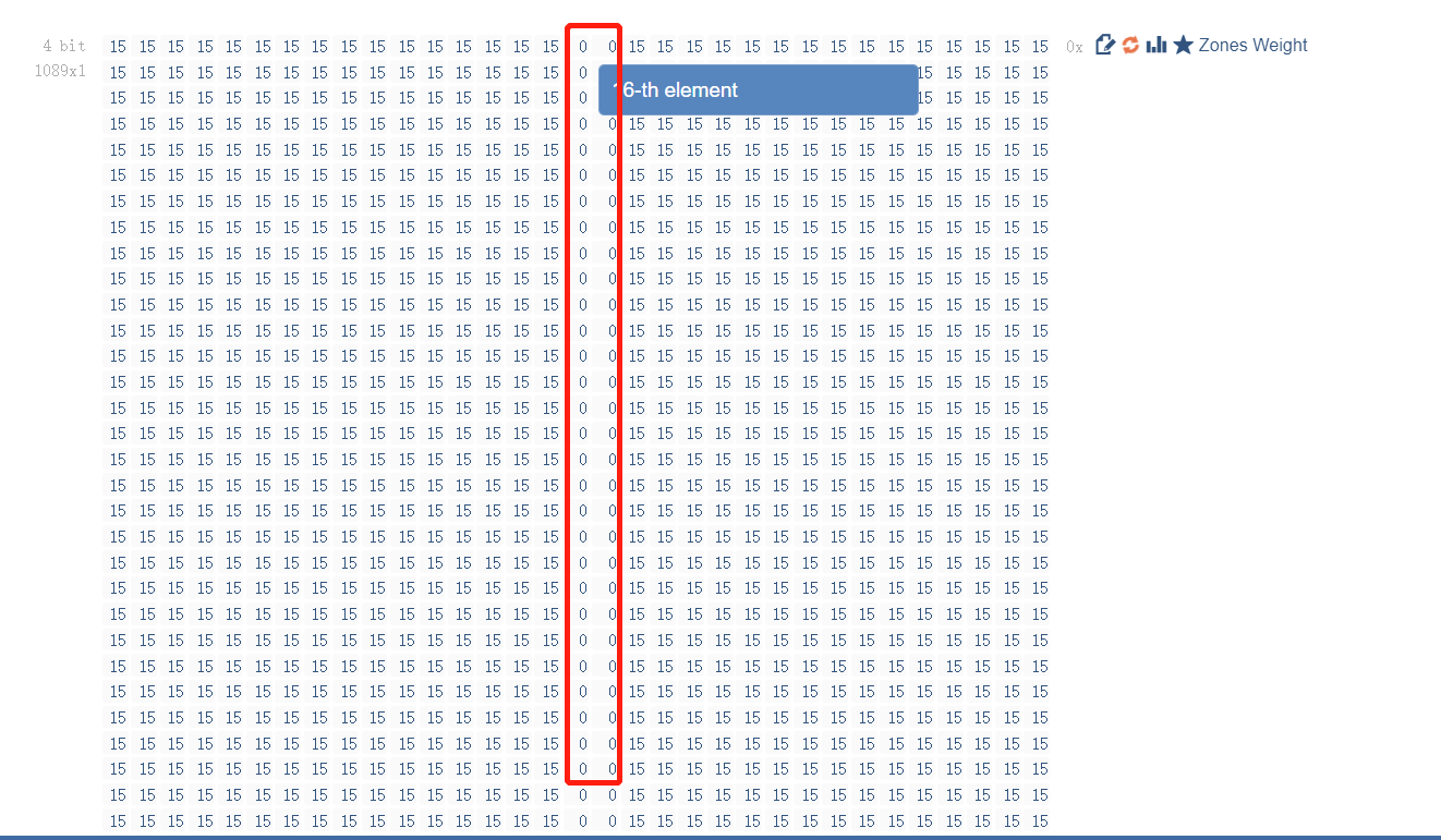
Figure 2

Figure 3
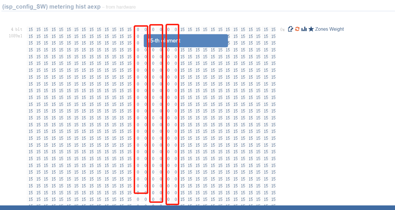
Figure 4
AE_ZONE_WGHT_VER follows a similar pattern for the horizontal axis, with the LUT index controlling the row count according to the same principle as AE_ZONE_WGHT_HOR.
Sample ISP Code Reference:
The ISP (Image Signal Processor) system code reference can be found in the sample_isp section.