时间同步方案
名词缩写及解释
| 缩写 | 解释 |
|---|---|
| GPS | Global Positioning System |
| RTC | Real_Time Clock |
| PHC | PTP hardware clock |
| PTP | precision time protocol |
| gPTP | precision time protocol, extension of PTP Protocol |
| MCU | Microcontroller Unit |
| UART | Universal Asynchronous Receiver/Transmitter |
| CAN | Controller Area Network |
| PPS | Pulse Per Second |
| NMEA | National Marine Electronics Association |
| NTP | Network Time Protocol |
| NIC | Network Interface Card |
ptp 时间同步
功能
该软件包含两个程序:ptp4l 和 phc2sys。这两个软件结合使用,就可以实现从 master 获取时间,同步 S100的 PHC 时间和 Linux 系统时间。
ptp4l 使用方法
命令行参数
ptp4l 支持 gptp 功能,可以作为 master,也可以作为 slave;如果作为 slave,可以从 master 获取时间,同步 S100的 PHC 时间和 RTC 时间。
可以通过 ptp4l -h 查看帮助信息:
  root@ubuntu:/userdata# ptp4l -h

  usage: ptp4l [options]

  Delay Mechanism

  -A Auto, starting with E2E
  -E E2E, delay request-response (default)
  -P P2P, peer delay mechanism

  Network Transport

  -2 IEEE 802.3
  -4 UDP IPV4 (default)
  -6 UDP IPV6

  Time Stamping

  -H HARDWARE (default)
  -S SOFTWARE
  -L LEGACY HW

  Other Options

  -f [file] read configuration from 'file'
  -i [dev] interface device to use, for example 'eth0'
  (may be specified multiple times)
  -p [dev] Clock device to use, default auto
  (ignored for SOFTWARE/LEGACY HW time stamping)
  -s slave only mode (overrides configuration file)
  -l [num] set the logging level to 'num'
  -m print messages to stdout
  -q do not print messages to the syslog
  -v prints the software version and exits
  -h prints this message and exits
配置文件的使用
ptp4l 可以通过-f 参数指定配置文件。
配置文件按段划分,空行和#开头的行会被忽略。
有三种段类型:
[global]段,用来配置 program 选项,clock 选项,默认 port 选项。
port 段使用被配置的网口的名字,如[eth0]段,其配置的选项会覆盖[global]段中默认 port 选项。port 段可以为空内容,作用只是指定网口,这样命令行中不必使用-i 选项。
[unicast_master_table]段,配置单播 table。
配置文件的详细信息可以参考:https://linuxptp.nwtime.org/documentation/ptp4l/
automotive 配置示例
automotive-master.cfg:
#
# Automotive Profile example configuration for master containing those
# attributes which differ from the defaults.  See the file, default.cfg, for
# the complete list of available options.
#
[global]
# Options carried over from gPTP.
gmCapable       1
priority1       248
priority2       248
logSyncInterval     -3
syncReceiptTimeout  3
neighborPropDelayThresh 800
min_neighbor_prop_delay -20000000
assume_two_step     1
path_trace_enabled  1
follow_up_info      1
transportSpecific   0x1
ptp_dst_mac     01:80:C2:00:00:0E
network_transport   L2
delay_mechanism     P2P
#
# Automotive Profile specific options
#
BMCA            noop
masterOnly      1
inhibit_announce    1
asCapable               true
inhibit_delay_req       1
automotive-slave.cfg:
#
# Automotive Profile example configuration for slaves containing those
# attributes which differ from the defaults.  See the file, default.cfg, for
# the complete list of available options.
#
[global]
#
# Options carried over from gPTP.
#
gmCapable       1
priority1       248
priority2       248
logSyncInterval     -3
syncReceiptTimeout  3
neighborPropDelayThresh 800
min_neighbor_prop_delay -20000000
assume_two_step     1
path_trace_enabled  1
follow_up_info      1
transportSpecific   0x1
ptp_dst_mac     01:80:C2:00:00:0E
network_transport   L2
delay_mechanism     P2P
#
# Automotive Profile specific options
#
BMCA            noop
slaveOnly       1
inhibit_announce    1
asCapable               true
ignore_source_id    1
# Required to quickly correct Time Jumps in master
step_threshold          1
operLogSyncInterval     0
operLogPdelayReqInterval 2
msg_interval_request     1
servo_offset_threshold   30
servo_num_offset_values  10
phc2sys 使用方法
phc2sys 用于将 linux 系统时间同步到 phc 时间,或者将 phc 时间同步到 linux 系统时间。
可以通过 phc2sys --h 查看使用说明:
  root@ubuntu:/userdata# phc2sys -h

  usage: phc2sys [options]


  automatic configuration:
  -a turn on autoconfiguration
  -r synchronize system (realtime) clock
  repeat -r to consider it also as a time source
  manual configuration:
  -c [dev|name] slave clock (CLOCK_REALTIME)
  -d [dev] master PPS device
  -s [dev|name] master clock
  -O [offset] slave-master time offset (0)
  -w wait for ptp4l
  common options:
  -f [file] configuration file
  -E [pi|linreg] clock servo (pi)
  -P [kp] proportional constant (0.7)
  -I [ki] integration constant (0.3)
  -S [step] step threshold (disabled)
  -F [step] step threshold only on start (0.00002)
  -R [rate] slave clock update rate in HZ (1.0)
  -N [num] number of master clock readings per update (5)
  -L [limit] sanity frequency limit in ppb (200000000)
  -M [num] NTP SHM segment number (0)
  -u [num] number of clock updates in summary stats (0)
  -n [num] domain number (0)
  -x apply leap seconds by servo instead of kernel
  -z [path] server address for UDS (/var/run/ptp4l)
  -l [num] set the logging level to 'num' (6)
  -t [tag] add tag to log messages
  -m print messages to stdout
  -q do not print messages to the syslog
  -v prints the software version and exits
  -h prints this message and exits
综合示例
命令行参数
下面示范如何通过 ptp4l 和 phc2sys,将 master 的网卡时间同步到 slave 的网卡时间和系统时间。用户需要保证 master 设备和 slave 设备之间网络联通。
Master 端执行如下命令:
ptp4l -i eth0 -f /usr/hobot/lib/pkgconfig/automotive-master.cfg -m -l 7
Slave 端执行如下命令:
  ptp4l -i eth0 -f /usr/hobot/lib/pkgconfig/automotive-slave.cfg -m -l 7 > ptp4l.log &
  phc2sys -s eth0 -c CLOCK_REALTIME --transportSpecific=1 -m --step_threshold=1000 -w > phc2sys.log &
Log 示例
Slave 端 log:
  ptp4l[8330.884]: PI servo: sync interval 1.000 kp 0.700 ki 0.300000
  ptp4l[8330.885]: master offset 21 s3 freq -391 path delay 690
  ptp4l[8330.998]: port 1: delay timeout
  ptp4l[8330.999]: delay filtered 689 raw 687
  ptp4l[8331.884]: master offset 35 s3 freq -371 path delay 689
  ptp4l[8332.885]: master offset 47 s3 freq -349 path delay 689
  ptp4l[8333.885]: master offset 50 s3 freq -332 path delay 689
  ptp4l[8334.885]: master offset 22 s3 freq -345 path delay 689
Master 端 log:
  ptp4l[3469.136]: config item /var/run/ptp4l.inhibit_delay_req is 1
  ptp4l[3469.136]: config item (null).uds_address is '/var/run/ptp4l'
  ptp4l[3469.136]: port 0: INITIALIZING to LISTENING on INIT_COMPLETE
  ptp4l[3469.136]: config item (null).slaveOnly is 0
  ptp4l[3469.136]: port 1: received link status notification
  ptp4l[3469.136]: interface index 2 is up
  ptp4l[3469.261]: port 1: master sync timeout
  ptp4l[3469.386]: port 1: master sync timeout
  ptp4l[3469.511]: port 1: master sync timeout
  ptp4l[3469.636]: port 1: master sync timeout
  ptp4l[3469.761]: port 1: master sync timeout
  ptp4l[3469.886]: port 1: master sync timeout
ptp 时间同步方案
硬件特性限制,驱动实现不能同时支持 E2E/P2P。S100默认支持使用 P2P 延迟测量机制。
硬件特性限制,驱动实现不能同时支持 E2E/P2P。S600默认支持使用 P2P 延迟测量机制。
在使用 ptp 时间同步方案,比如雷达作为 ptp4l slave 且不支持 P2P 协议,需要使用 E2E 协议可以通过以下修改进行测试:
以下修改仅在 soc 作为 ptp4l master 时有效。此修改会影响 soc 作为 ptp4l slave 时的功能!
  diff --git a/ethernet/hobot/hobot_eth_super_ptp.c b/ethernet/hobot/hobot_eth_super_ptp.c
  index 0bfe2250..60577ea4 100755
  --- a/ethernet/hobot/hobot_eth_super_ptp.c
  +++ b/ethernet/hobot/hobot_eth_super_ptp.c
  @@ -238,6 +238,7 @@ static void ptp_hwtstamp_ctr_config(struct hwtstamp_config *config, struct hwtst
                          break;
                  case (s32)HWTSTAMP_FILTER_PTP_V2_EVENT:
                          ctr_config->ptp_v2 = (u32)PTP_TCR_TSVER2ENA;
  +                       ctr_config->ts_master_en = (u32)PTP_TCR_TSMSTRENA;
                          ctr_config->snap_type_sel = PTP_GMAC4_TCR_SNAPTYPSEL_1;/*PRQA S 1882, 0478, 0636, 4501*/
                          ctr_config->ptp_over_ipv4_udp = (u32)PTP_TCR_TSIPV4ENA;
                          ctr_config->ptp_over_ipv6_udp = (u32)PTP_TCR_TSIPV6ENA;
全局时间源配置
由于当前系统中存在多个 timeline,比如 systime、phc、rtc 等,而各个模块支持选择不同的 timeline 来打印各自的时间戳。为了统一各个模块的日志中时间戳的 timeline,添加了一个 hb_systime 的模块,来统一系统各个模块的 timeline 的选择。该模块实现的具体功能如下:
解析 dts 里默认的 timeline 的配置,如下:
  globaltime: globaltime {
    compatible = "hobot,globaltime";
    globaltime = <2>; /* 0-systime, 1-phc, 2-rtc */
    phc-index = <0>; /* phc index */
    status = "okay";
  };
其中 dts 中 globaltime 属性表示系统默认用的全局 timeline,默认使用 RTC 时间。对应关系如下:
  0:systime
  1:phc
  2:rtc
如果 timeline 选中网卡 phc 时间, 则通过 phc-index 属性进一步判断当前使用哪个网卡 phc 的时间。对应关系如下:
  0:phc0
  1:phc1
向应用层提供/sys 接口用来设置或者获取当前系统全局的 timeline 的选择,命令如下:
查看当前系统全局的 timeline 的配置:
cat /sys/devices/platform/soc/soc:globaltime/globaltime
设置系统全局 timeline 的选项:
  echo 0 >/sys/devices/platform/soc/soc:globaltime/globaltime
  或
  echo 1 >/sys/devices/platform/soc/soc:globaltime/globaltime
  或
  echo 2 >/sys/devices/platform/soc/soc:globaltime/globaltime
向应用层提供/sys 接口用来设置或者获取当前选中的 phc 编号
查看当前选中的 phc 编号:
cat /sys/devices/platform/soc/soc:globaltime/phcindex
设置 phc 编号:
  echo 0 >/sys/devices/platform/soc/soc:globaltime/phcindex
  或
  echo 1 >/sys/devices/platform/soc/soc:globaltime/phcindex
📍 注意: phcindex 设置不要超过网卡实际数量。
向内核其他模块提供接口,查看当前系统用的哪个 timeline,以及使用的是哪个 phc,如下:
  int32_t hobot_get_global_time_type(uint32_t *global_time_type);
  int32_t hobot_get_phc_index(uint32_t *phc_index);
MCU 时间同步说明
MCU 支持的时间类型
PHC 时间:这个是网卡内部的一个计时器;
RTC 时间:这个是 MCU 侧带的一个实时时钟,不支持通过纽扣电池供电;
MCU 支持的时间同步方式
MCU 支持下面的时间同步方式:
基于 PPS 的 Timesync:在秒脉冲上升沿捕捉到两个时间的 snapshot,根据 snapshot 计算误差,根据误差进行时间同步;
基于 PPS 的 Timesync
代码目录: mcu/Service/TimeSync/src/
支持的时间
- RTC
- PHC
配置方法
通过修改配置决定使用哪种时间同步方式。配置代码在./Service/TimeSync/src/Hobot_TimeSync.c 文件中。目前只是支持下面一种时间同步方式:
PHC 同步 RTC
  /*TimeSync Config Begin*/
  uint8 ConfigSource[] = {
    TIMEKEEPER_NONE, //TimeKeeperRTC Source
    TIMEKEEPER_NONE, //TimeKeeperGPS Source
    TIMEKEEPER_NONE, //TimeKeeperStbmPhc Source //Not Used in S100
    TIMEKEEPER_NONE, //TimeKeeperSpi Source
    TIMEKEEPER_NONE, //TimeKeeperIPC Source
    TIMEKEEPER_NONE, //TimeKeeperPHC Source
    TIMEKEEPER_NONE //TimeKeeperGpt Source //Not Used in S100
  };

  _Bool EnableTimeKeeper[] = {
    FALSE,//TimeKeeperRTC
    FALSE,//TimeKeeperGPS
    FALSE,//TimeKeeperStbmPhc //Not Used in S100
    FALSE,//TimeKeeperSpi
    FALSE,//TimeKeeperIPC
    FALSE,//TimeKeeperPHC
    FALSE//TimeKeeperGpt //Not Used in S100
  };

  _Bool Enable_TimeSync_RTC_Once= FALSE;

  _Bool Enable_HobotTimesync_Debug = FALSE;
  _Bool EthTsync_Master_Use_Phc = TRUE;
  uint8 TimeSync_PPS_Index = TIMESYNC_MCU_ETH0_PPS;

  /*TimeSync Config End*/
ConfigSource:配置每个时间的时间源,如果一个时间不需要和其他时间同步,时间源配置成 TIMEKEEPER_NONE。
可以配置的时间源为 :
  typedef enum TimeKeeperIndexEnum {
    TIMEKEEPER_RTC_INDEX,
    TIMEKEEPER_GPS_INDEX,
    TIMEKEEPER_STBMPHC_INDEX, //Not Used in S100
    TIMEKEEPER_SPI_INDEX,
    TIMEKEEPER_IPC_INDEX,
    TIMEKEEPER_PHC_INDEX,
    TIMEKEEPER_STBMGPT_INDEX, //Not Used in S100
    TIMEKEEPER_NONE,
    TIMEKEEPER_NUM_MAX,
  } TimeKeeperIndex;
EnableTimeKeeper: 配置时间是否打开 ;
Enable_HobotTimesync_Debug: 配置是否开启打印 ;
TimeSync_PPS_Index: 配置使用哪个 PPS 进行时间同步,可以使用的 PPS 如下 :
  #define TIMESYNC_AON_RTC_PPS 0
  #define TIMESYNC_PPS0 2
  #define TIMESYNC_PPS1 3
  #define TIMESYNC_PPS2 4
  #define TIMESYNC_PCIE0_PTM_PPS 6
  #define TIMESYNC_PCIE1_PTM_PPS 7
  #define TIMESYNC_ACORE_ETH0_PPS 8
  #define TIMESYNC_ACORE_ETH1_PPS 9
  #define TIMESYNC_MCU_ETH0_PPS 10
  #define TIMESYNC_PPS_DISABLE 11
配置举例
如果想配置 RTC 和 GPS 进行时间同步, 配置如下:
  /*TimeSync Config Begin*/
  uint8 ConfigSource[] = {
    TIMEKEEPER_GPS_INDEX, //TimeKeeperRTC Source
    TIMEKEEPER_NONE, //TimeKeeperGPS Source
    TIMEKEEPER_NONE, //TimeKeeperStbmPhc Source //Not Used in S100
    TIMEKEEPER_NONE, //TimeKeeperSpi Source
    TIMEKEEPER_NONE, //TimeKeeperIPC Source
    TIMEKEEPER_NONE, //TimeKeeperPHC Source
    TIMEKEEPER_NONE //TimeKeeperGpt Source //Not Used in S100
  };

  _Bool EnableTimeKeeper[] = {
    TRUE,//TimeKeeperRTC
    TRUE,//TimeKeeperGPS
    FALSE,//TimeKeeperStbmPhc //Not Used in S100
    FALSE,//TimeKeeperSpi
    FALSE,//TimeKeeperIPC
    FALSE,//TimeKeeperPHC
    FALSE//TimeKeeperGpt //Not Used in S100
  };

  _Bool Enable_TimeSync_RTC_Once= FALSE;

  _Bool Enable_HobotTimesync_Debug = FALSE;
  /*TimeSync Config End*/
PPS 说明
S100 PPS 介绍
S600 PPS 介绍
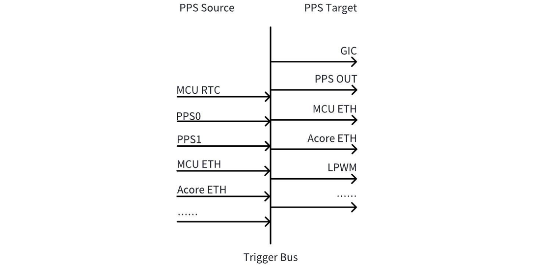
如上图所示,PPS 可以分为 PPS Source 和 PPS Target。PPS Source 产生 PPS,经过中间的 Trigger Bus 送到 PPS Target,PPS Target 利用送来的 PPS 产生 snapshot 或者 LPWM 波形。
PPS Target
PPS Target 表示被 PPS 触发的对象,用于产生 snapshot 或者 LPWM 波形,目前使用 PPS 触发的对象主要有以下几个:
PPS OUT:PPS2的管脚复用在当前软件版本上默认是设置为 PPS OUT 的,即可以通过这个 pad 脚将芯片内的 PPS 向外输出到片外;
GIC:当前软件版本默认将 MCU RTC,PPS0,PPS1,PPS2和 MCU ETH PPS 的中断给到了 GIC;
Acore ETH:Acore ETH 可以接受 PPS 源,并通过 PPS 打自身硬件的 snapshot 时间;
LPWM:LPWM 可以接受 PPS 源输入,并通过 PPS 产生对应的 LPWM 波形;
PPS Source
PPS source 有多个源可选,其中常用的源有以下几个,其它是 reserve 的:
编号0:MCU RTC PPS,是 MCU 侧 RTC 输出的 PPS,当前软件版本默认已有输出,周期1秒1次;
编号2:PPS0,PPS 的 pad,可用于 GPS PPS 等外部 PPS 源输入到芯片内部;
编号3:PPS1,PPS 的 pad,可用于 GPS PPS 等外部 PPS 源输入到芯片内部;
编号4:PPS2,PPS 的 pad,可用于 GPS PPS 等外部 PPS 源输入到芯片内部,也可以用于将内部的 PPS 输出到外部;
编号8:Acore Eth0 PPS, 是 Acore Eth0产生的 PPS,可以设置灵活的时间周期,比如1秒1次,400毫秒1次等;
编号9:Acore Eth1 PPS, 是 Acore Eth1产生的 PPS;可以设置灵活的时间周期,比如1秒1次,400毫秒1次等;
编号10:MCU Eth PPS,是 MCU 侧 Eth 输出的 PPS,当前软件版本默认已有输出,周期1秒1次;
PPS source 有多个源可选,其中常用的源有以下几个,其它是 reserve 的:
编号0:MCU RTC PPS,是MCU侧RTC输出的PPS,当前软件版本默认已有输出,周期1秒1次;
编号2:PPS0,PPS的pad,可用于GPS PPS等外部PPS源输入到芯片内部;
编号3:PPS1,PPS的pad,可用于GPS PPS等外部PPS源输入到芯片内部;
编号4:PPS2,PPS的pad,可用于GPS PPS等外部PPS源输入到芯片内部,也可以用于将内部的PPS输出到外部;
编号8:Acore gmac PPS, 是Acore gmac(千兆网卡)产生的PPS,可以设置灵活源为gmac0、 gmac1或gmac2,周期1秒1次。
编号9:Acore xgmac PPS, 是Acore xgmac(万兆网卡)产生的PPS;可以设置灵活源为xgmac0、 xgmac1或xgmac2,周期1秒1次。
PPS 的 PAD 配置
当前软件版本默认将 PPS0和 PPS1设置为了 PPS 的 IN,即用于接收 GPS PPS 等外部 PPS 的输入;把 PPS2设置为了 PPS 的 OUT,即将芯片的 PPS 输出到外部; 它们的配置均由 MCU 侧的 Port 模块进行了配置,如需要修改,则在 Port 模块中进行修改。
以将 PPS2 pin 脚配置为输出,将芯片 ETH PPS 输出到外部为例说明修改方法:
- 修改 Port 配置的默认 pps_source 为 ETH PPS
 static const Port_Lld_PpsConfigType PpsConfig =
 {
     (boolean)TRUE,
-    PPS_SOURCE_AON_RTC,
+    PPS_SOURCE_ETH0_PTP,
 };
- 将 pin 脚配置成 PPS_OUT func
-    {(uint8)2, "PPS_OUT", (boolean)TRUE, {(boolean)TRUE, (boolean)FALSE, (boolean)TRUE, (boolean)TRUE, (boolean)TRUE, GPIO, PORT_PIN_CONFIG_TYPE0, PORT_PULL_NONE, PORT_DRIVE_DEFAULT, PORT_PIN_DIR_OUT, PORT_PIN_LEVEL_HIGH}},
+    {(uint8)2, "PPS_OUT", (boolean)TRUE, {(boolean)TRUE, (boolean)FALSE, (boolean)TRUE, (boolean)TRUE, (boolean)TRUE, PPS_OUT, PORT_PIN_CONFIG_TYPE0, PORT_PULL_NONE, PORT_DRIVE_DEFAULT, PORT_PIN_DIR_OUT, PORT_PIN_LEVEL_HIGH}},
以上通过修改McalCdd/gen_s100_sip_B/Port/src/Port_PBcfg.c实现,修改完成后更新 MCU 固件即可。
- 修改 Port 配置的默认 pps_source 为 ETH PPS
 static const Port_Lld_PpsConfigType PpsConfig =
 {
     (boolean)TRUE,
-    PPS_SOURCE_AON_RTC,
+    PPS_SOURCE_ETH0_PTP,
 };
- S600上 PIN 脚默认功能即为 PPS OUT FUNC,因此不需要修改。
以上通过修改McalCdd/gen_s600_md/Port/src/Port_PBcfg.c实现,修改完成后更新 MCU 固件即可。
Acore Eth PPS 介绍
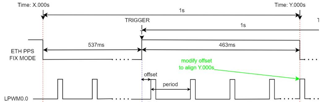
Acore Eth PPS 有两种输出方法,flex mode 和 fix mode 两种。上电默认是 fix mode。可以通过下文中 ethtool 命令设置为 flex mode。若要重置为 fix mode,可以通过重启网卡或者重启系统完成恢复。
flex mode: 灵活的 pps 模式,它的开始/结束时间、周期、占空比均可以灵活配置,其上升沿是整秒时刻,PPS 输出不会随着 PHC 时间的变化而变化;当前软件版本下,其占空比是百分之一,周期可以根据下方配置方法灵活配置,常用的有1s,400ms。
fixed mode: 固定的 pps 模式,它的周期固定,且占空比也固定为46.3129%。PPS 输出会随着 PHC 时间的变化而变化。当前软件版本下,其支持1s 周期,波形的整秒时刻是下降沿,经过536.871ms 的低电平后,再输出463.129ms 的高电平。
整秒输出需求配置方法:
若在 flex mode 下有整秒时刻输出 PPS 的需求,需要在 gptp 时间同步完成后,再配置 PPS 输出;
若在 fixed mode 下有整秒时刻输出 PPS 的需求,需要注意 ETH 的整秒时刻在下降沿出现,而 LPWM 被 ETH 上升沿同步。因此需要参考下图,调整 LPWM 的 offset。以 camera 一秒30帧举例,PPS 上升沿在536.871ms,下降沿在1s 整秒处,要求在整秒位置出图的话,offset=463.129对33.333取余数=29.8ms。
Acore Eth PPS有两种输出方法,flex mode和fix mode两种。上电默认是fix mode。可以通过下文中ethtool命令设置为flex mode。若要重置为fix mode,可以通过重启网卡或者重启系统完成恢复。
flex mode: 灵活的pps模式,它的开始/结束时间、周期、占空比均可以灵活配置,其上升沿是整秒时刻,PPS输出不会随着PHC时间的变化而变化;当前软件版本下,其占空比是百分之一,周期可以根据下方配置方法灵活配置,常用的有1s,400ms。
fixed mode: 固定的pps模式,它的周期固定,S600加入极性反转,因此占空比固定为53.6871%。PPS输出会随着PHC时间的变化而变化。当前软件版本下,其支持1s周期,波形的整秒时刻是上升沿,经过536.871ms的高电平后,再输出463.129ms的低电平。
整秒输出需求配置方法:
若在flex mode下有整秒时刻输出PPS的需求,需要在gptp时间同步完成后,再配置PPS输出;
S600 平台具备多个网卡资源。底板对外引出的网卡接口规格为1xGMAC/3xXGMAC,但当前硬件实际支持3xGMAC。目前系统使用的网卡为基地址 0x33110000 的GMAC;而上电默认fix mode输出的PPS信号由基地址 0x330f0000 的GMAC输出(该GMAC已复用于其他功能)。
当业务需要由当前使用的 GMAC 输出 PPS 信号时,请执行以下命令进行配置:
-
timesync_sample示例代码中新增timesyncClockGeneratePPS接口调用,用于根据用户选择的网卡配置产生ETH PPS的信号源
-
不需要启动timesync_sample时,用户可执行以下命令进行配置:
ts2phc -c /dev/ptp[x] -s eth[y] generic --ts2phc.channel 0
参数说明如下:
eth[y]:根据 ifconfig 输出,确定目标网卡对应的接口编号。
/dev/ptp[x]:根据ethtool -T eth[y]输出中的PTP Hardware Clock: *,选择对应的PTP设备编号。
完成网卡与PTP设备的对应关系确认,再执行ts2phc,以避免将PPS配置到错误的网卡实例。
以上配置需在时间同步前执行。
Acore Eth PPS 的输出配置方法
Acore Eth PPS 的输出,可以借助 ethtool 工具,命令格式如下 :
配置 Eth0的 PPS 输出1秒的周期:ethtool hobot_gmac --set-flex-pps eth0 index 0 fpps on interval 1000000000;
配置 Eth1的 PPS 输出1秒的周期:ethtool hobot_gmac --set-flex-pps eth1 index 0 fpps on interval 1000000000;
如果需要修改输出周期的话,修改最后一个参数<1000000000>,该参数的单位是 ns,如果要修改为400ms 的话,则改为<400000000>。
Acore Eth PPS配置为flex输出,可以借助ethtool工具,命令格式如下:
ethtool hobot_gmac --set-flex-pps ethX index 0 fpps on interval 1000000000;
需要注意的是ethX是和硬件IP实例对应的,与ifconfig命令看到的ethX并不一定完全对应,对应关系取决于dts对于网卡的配置。
用户可根据ethtool -T ethX输出中的PTP Hardware Clock: *确定当前X对应的编号是多少。
当前软件版本默认配置为fixed mode,固定输出周期为1s。如果需要修改输出周期的话,需要先在内核dts中配置选择hobot,pps = <0>;切换成flex mode。然后修改最后一个参数<1000000000>,该参数的单位是ns,如果要修改为400ms的话,则改为<400000000>。
不论是gmac还是xgmac,ethtool配置的命令格式都是:ethtool hobot_gmac –set-flex-pps eth0 index 0 fpps on interval 1000000000,只有ethX和最后一个参数配置有差异。
MCU Eth PPS 的配置方法
MCU Eth PPS 的信号周期和脉冲宽度在Config/McalCdd/gen_s100_sip_B_mcu1/Ethernet/src/Mac_Ip_PBcfg.c配置文件中设置默认值,其中 PpsInterval 的默认值为1000(ms),参数 PpsWidth 的默认值为10(ms)。
MCU Eth PPS 的信号周期和脉冲宽度在Config/McalCdd/gen_s600_md_mcu1/Ethernet/src/Mac_Ip_PBcfg.c配置文件中设置默认值,其中 PpsInterval 的默认值为1000(ms),参数 PpsWidth 的默认值为10(ms)。
限制条件:
- 配置项 EthGlobalTimeSupport 需要被使能,默认使能;
- 参数 PpsWidth 的值必须小于 PpsInterval;
配置使能后通过查看 sys 节点 assert 变化确认 PPS 配置是否生效。
cat /sys/class/pps/pps[4]/assert
/sys/class/pps 下包含多个 pps,通过 name 确认哪个 PPS 对应 MCU PPS。
cat /sys/class/pps/pps[*]/name
时间同步整体方案
功能概述
本章节主要以 S100为例,介绍时间同步方案。目前主线默认没有启动时间同步,如果有默认启动时间同步的需求,参考运行指南章节说明,配置即可。
软件架构说明
时间源接入 Acore 的单时间域方案
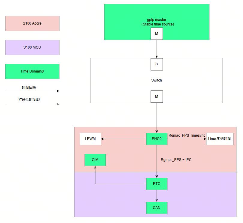
上图时间同步流程总结如下:
-
外部 gptp master 设备作为整个 S100的时间源;
-
首先通过 ptp4l 软件将 gptp master 的时间同步给 Acore 侧的网卡;然后通过 phc2sys 将网卡时间同步给 Linux 系统时间,该过程持续进行;
-
接下来通过 Acore timesync_sample 软件将网卡时间同步给 MCU 侧 Rtc;
特性说明:
-
Rtc 支持给图中的 CIM 和 CAN 打硬件时间戳;
-
Acore 网卡可以发出 pps,触发 lpwm 进行曝光同步;
代码位置及目录结构
Acore 侧 timesync sample 代码位于工程目录:{sdk_dir}/source/hobot-sp-samples/debian/app/timesync_demo
MCU 侧 timesync sample 代码位于工程目录:{mcu_dir}/mcu/Service/TimeSync
Acore 编译
编译环境
板端在安装 hobot-sp-samples_*.deb 包后,会包含 timesync_demo 源码内容。
编译说明
本 sample 主要依赖 ipcfhal 和 timesync 提供的 API 头文件
#include "hb_ipcf_hal.h"
#include "hobot_clock_hal.h"
编译依赖的库有如下:
LIBS := -lhbipcfhal -lhbtimesynchal -lpthread -lalog
编译命令:
板端进入/app/timesync_demo/sample_timesync 目录,执行
make
MCU 编译
编译环境
MCU 侧本 sample 的编译环境使用 MCU 代码中的 build 工具,请参考:MCU编译。
编译 FreeRtos 镜像版本。注意
  # 进入Build/FreeRtos目录
  python build_freertos.py lite matrix B s100 gcc debug # 硬件板或者项目名
  python build_freertos.py lite matrix B s600 gcc debug # 硬件板或者项目名
运行
支持平台
S100/S600
板端部署及配置
需要做好如下准备工作:
烧写好支持 MCU 侧时间同步服务的 MCU 固件。
若需要运行 gptp 时间同步,需要保证网络连通。
为了防止 Linux 操作系统自带时间同步服务产生干扰,需要执行如下命令关闭 Linux 自带时间同步服务。
systemctl stop systemd-timesyncd
运行指南
时间源接入 Acore 的单时间域方案
MCU 侧在./Service/TimeSync/src/Hobot_TimeSync.c 代码中进行如下配置修改:
/* Timesync Config Begin */
uint8_t ConfigSource[] = {
    TIMEKEEPER_IPC_INDEX,   // TimeKeeperRTC Source
    TIMEKEEPER_NONE,        // TimeKeeperGPS Source
    TIMEKEEPER_IPC_INDEX,   // TimeKeeperStbmPhc Source
    TIMEKEEPER_NONE,        // TimeKeeperSpi Source
    TIMEKEEPER_NONE,        // TimeKeeperIPC Source
    TIMEKEEPER_NONE,        // TimeKeeperPHC Source
    TIMEKEEPER_NONE         // TimeKeeperGpt Source
};

_Bool EnableTimeKeeper[] = {
    TRUE,
    FALSE,
    FALSE,
    FALSE,
    TRUE,
    FALSE,
    FALSE
};

_Bool Enable_TimeSync_RTC_Once = FALSE;

_Bool Enable_HobotTimesync_Debug = TRUE;
MCU 侧的修改需要注意 PRODUCT_IMAGE 宏的影响,详细内容请参考上述注意事项章节。
刷写启动后,默认 MCU 执行如下命令,第一条命令指定 PPS 触发源为 mcu eth;第二条命令启动时间同步服务
  TimeSyncCtrl 4 10
  TimeSyncCtrl 6
其中,打开 MCU 侧日志打印命令如下:
TimeSyncCtrl 1
MCU 默认不启动时间同步服务。如果配置默认启动,除了修改以上描述的配置,另外需要增加初始化的动作,参考如下:
TASK(OsTask_SysCore_Startup)
{
  ......
  Timesync_Init();
  ......
}
完成以上配置,在加载 MCU1固件后,时间同步服务默认启动,不再需要执行TimeSyncCtrl的命令。
Acore 执行如下命令,第一条命令设置 log 等级,允许输出打印到控制台;第二条命令启动 ptp 时间同步,将外部 ptp master 时间同步到 Acore 网卡; 第三条命令将网卡时间同步到 Linux 系统时间;第五条命令启动时间同步程序,将 Acore 网卡时间同步给 MCU 侧 Rtc。
export LOGLEVEL=15
ptp4l -i eth0 -f /usr/hobot/lib/pkgconfig/automotive-slave.cfg -m -l 7 > ptp4l.log &
phc2sys -s eth0 -c CLOCK_REALTIME --transportSpecific=1 -m --step_threshold=1000 -w > phc2sys.log &
cd /app/timesync_demo/sample_timesync
./timesync_sample -p 0 -P 4 -r
关键参数说明:
-p 1: 同步网卡1的时间; -p 0: 同步网卡0的时间(默认)
-r: 将 Acore 网卡时间同步给 MCU Rtc 时间
Acore 时间同步 log 如下:
[INFO][][/app/timesync_demo/sample_timesync/timesync_sample.c:510] ************************************************
[INFO][][/app/timesync_demo/sample_timesync/timesync_sample.c:517] Monotonic_raw time: second = 222, nanosecond = 557846725
[INFO][][/app/timesync_demo/sample_timesync/timesync_sample.c:520] PPS fetch infobuf time: second = 1745925136, nanosecond = 454616475
[INFO][][/app/timesync_demo/sample_timesync/timesync_sample.c:531] rtc snapshot: sec = 1745925136, nsec = 455389596
[INFO][][/app/timesync_demo/sample_timesync/timesync_sample.c:538] ptp0 snapshot: sec = 1745925136, nsec = 455462040
[INFO][][/app/timesync_demo/sample_timesync/timesync_sample.c:582] Timesync Info: timesync ipc send data succeed
[INFO][][/app/timesync_demo/sample_timesync/timesync_sample.c:510] ************************************************
Acore log 说明:
"snapshot"字段为 MCU 网卡发出 pps 秒脉冲时各个 clock 对应的硬件时间戳;
"PPS fetch infobuf time"字段为 Acore pps 驱动捕获到的系统时间;
"timesync ipc send data succeed"提示说明 Acore 网卡时间戳成功发送给 MCU,由 MCU 侧进行时间同步,时间同步质量在 MCU 侧查看。
MCU 时间同步 log 如下:
[0162.799758 0]*
[0162.802970 0]RTC snapshot time:1745925071.455114934
[0163.000408 0]Timesync_RecvCallback.
[0163.000661 0]Get Time From Acore success 1745925071 455188935
[0163.001958 0]TimeKeeperRTC and TimeKeeperIPC Offset : - 0s.74001ns
[0163.789774 0]*
MCU log 说明:
"Get Time From Acore success" 表明 MCU 从 Acore 拿时间成功;
"TimeKeeperRTC and TimeKeeperIPC Offset" ,表明在同步时,Rtc 使用 IPC 时间同步时的 offset。