1.1.2 Camera Expansion Board

The RDK S100 Camera Expansion Board (hereinafter referred to as the "Camera Expansion Board") is a core expansion module of the D-Robotics RDK S100 series developer kit. Based on the RDK S100 Camera Expansion Connector, the Camera Expansion Board enables secondary development and provides 2 MIPI camera interfaces and 4 GMSL camera interfaces.
- This product is exclusively compatible with RDK S100 series mainboards. Do not use it with other device models.
- During use, place the expansion board on a stable, flat, non-conductive surface to prevent device drop or short circuits caused by unstable support.
- Damage caused by connecting incompatible devices to the RDK S100 CAMERA EXPANSION BOARD is not covered under warranty or repair services.
- All peripheral devices used with this product (including but not limited to camera modules and power adapters) must comply with safety and performance standards of the country/region of use and bear appropriate compliance certification markings.
- All cables and connectors of peripheral devices connected to this expansion board must provide sufficient insulation to meet electrical safety requirements.
To avoid malfunction or damage to this expansion board, strictly adhere to the following:
- Environmental Requirements: Do not expose the board to water, moisture, or conductive surfaces during operation. Keep it away from heat sources (e.g., radiators, direct sunlight) and ensure the ambient temperature complies with specifications in the product datasheet.
- Assembly Handling: Handle the board gently during assembly. Avoid applying mechanical stress or electrical interference (e.g., electrostatic discharge) to the printed circuit board (PCB) or connectors.
- Power-On Operation: Do not directly touch the PCB surface or metal interfaces on the board edges while powered on to minimize the risk of electrostatic discharge (ESD) damage.
- Before connecting a MIPI camera, ensure that the logic voltage level required by the MIPI camera matches the DIP switch settings to prevent communication errors or device damage.
- If adding a level-shifting IC, pay attention to the supported data rate range of the IC and its requirements for external pull-up/pull-down resistors.
- Pay attention to the position and definition of Pin 1 on the connectors of both the Camera Expansion Board and the camera. Procure or customize compatible ribbon cables according to the product’s physical structure.
- When fabricating FPC ribbon cables, ensure the integrity of the MIPI signal reference plane and implement proper impedance control.
Product Specifications
| Item | Specification |
|---|---|
| Deserializer | Maxim MAX96712 |
| MIPI Connectors | 2x 22-Pin MIPI CSI-2 |
| GMSL Connectors | Fakra-Mini 4in1 |
| External Power | 12V DC, required only when total current draw exceeds 700mA; maximum 2.4A. |
| Operating Temp. | 0℃ ~ 45℃ |
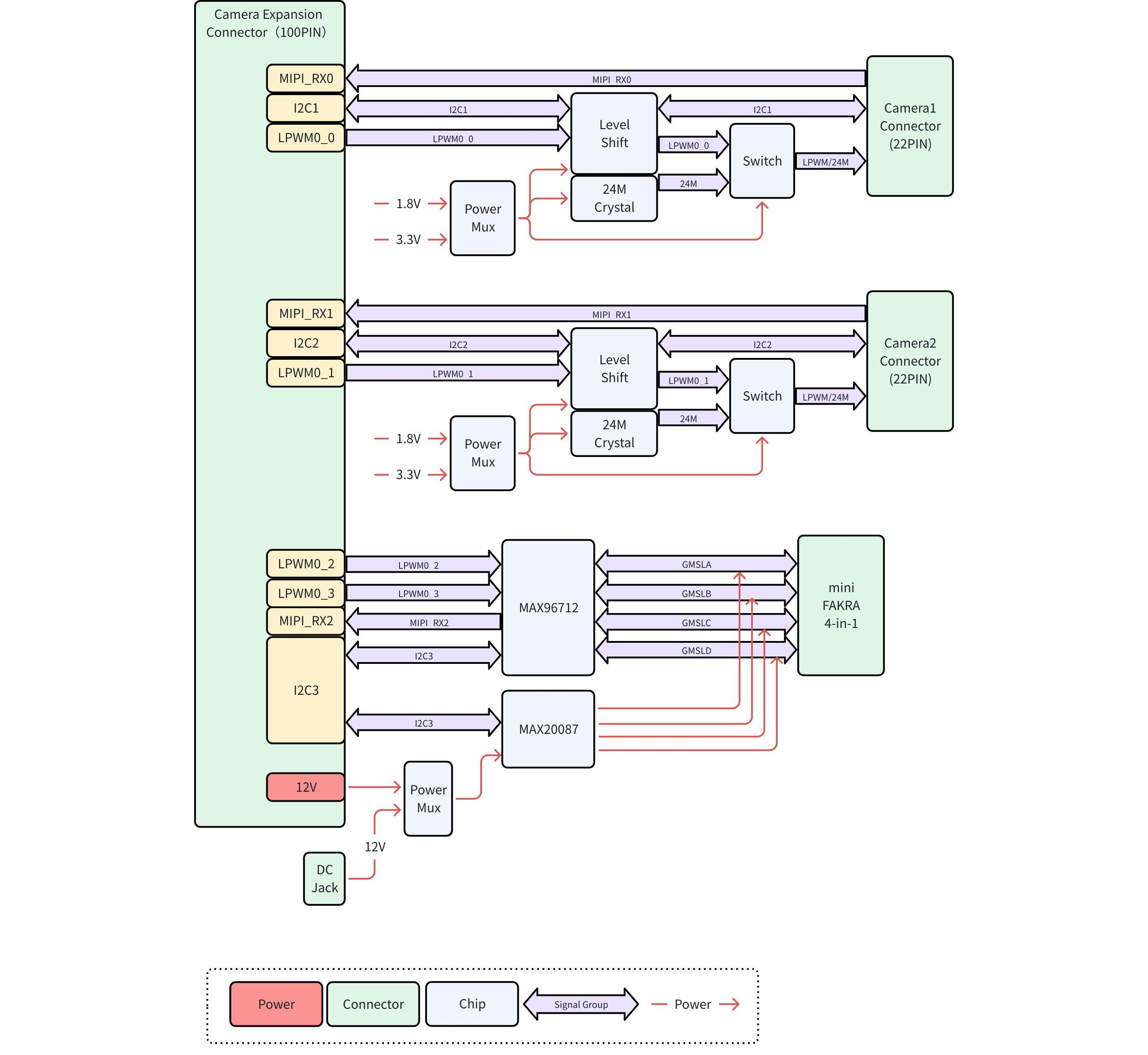
Topology Diagram
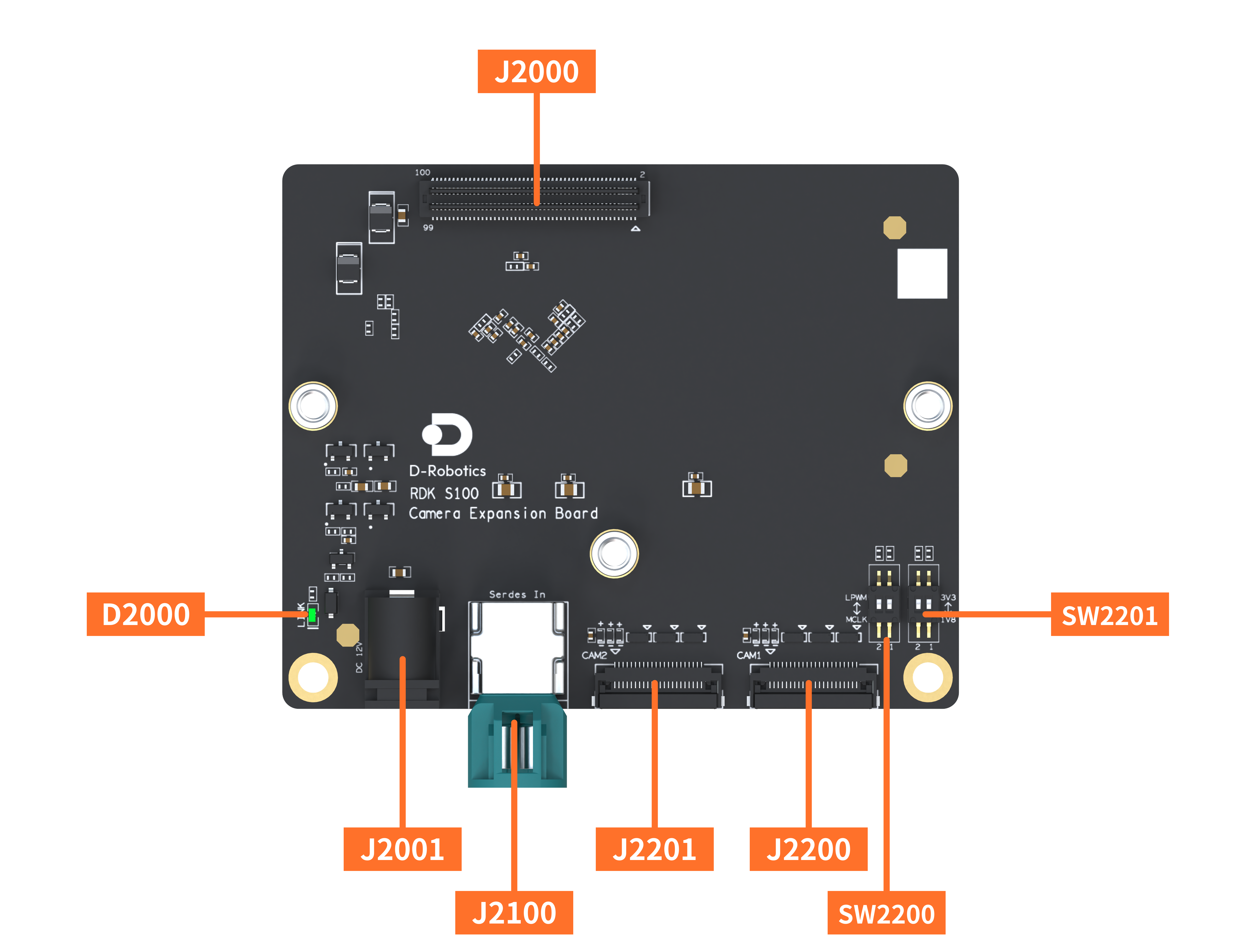
Interface Description
| Interface | Function | Interface | Function |
|---|---|---|---|
| J2000 | 100-Pin Connector | J2200 | MIPI Camera Interface 1 |
| D2000 | Power Indicator LED | J2201 | MIPI Camera Interface 2 |
| J2001 | DC Power Input | SW2200 | MIPI Camera Interface Function Switch |
| J2100 | GMSL Camera Interface | SW2201 | MIPI Camera Interface Voltage Switch |
Camera Installation Instructions
| Model | Hardware Interface | Function Switch SW2200 | Voltage Switch SW2201 |
|---|---|---|---|
| IMX219 Camera (Raspberry Pi 5 compatible) | J2200 / J2201 | lpwm | Yahboom 1.8V / Waveshare 3.3V |
| SC230AI Stereo Camera (V3) | J2200 & J2201 | lpwm | 3.3V |
| SC132GS Stereo Camera | J2200 & J2201 | lpwm | 3.3V |
| SG8S-AR0820C-5300-G2A | J2100 | - | - |
| LEC28736A11 (X3C Module) | J2100 | - | - |
| Intel RealSense D457 | J2100 | - | - |
| Intel RealSense D435i | USB | - | - |
Assembly Guide
- Perform installation only when the development board is powered off and the DC plug is disconnected.
- During installation, ensure the mainboard and expansion board remain parallel, connectors are evenly aligned and fully seated, and the connection is secure to avoid connector damage.
Please refer to the corresponding expansion board assembly video based on the actual product.
-
Threaded Standoff Expansion Board: Support standoffs have threaded inner walls.
-
Smooth Standoff Expansion Board: Support standoffs have smooth, non-threaded inner walls.

Threaded hole support post
Smooth hole support post
Interface Description
100-Pin Connector (J2000)
This is the connection port between the Camera Expansion Board and the RDK S100, providing functional interfaces (MIPI CSI and GPIO) and power (12V and 3.3V) to the Camera Expansion Board.
Ensure the connector between the Camera Expansion Board and the RDK S100 is fully seated and secured with mounting screws to guarantee reliable signal connections.
DC Power Input (J2001)
The Camera Expansion Board includes an external 12V DC power input for GMSL cameras. When the total 12V current requirement of all connected GMSL cameras exceeds 700mA, this DC power jack must be used to supply power to the GMSL cameras.
- Adapter plug specification: inner diameter 2.5mm, outer diameter 6mm.
- Adapter rated voltage must be 12V. Select an appropriate current rating based on the requirements of the connected GMSL camera modules.
GMSL Camera Interface (J2100)
The Camera Expansion Board integrates the MAX96712 deserializer chip, supporting up to 4 GMSL2 cameras and providing 12V power over coaxial cables to the GMSL cameras.
- When the total 12V current draw of GMSL cameras is ≤700mA, no external 12V adapter is needed—the 12V power is supplied by the RDK S100. If the current draw exceeds 700mA, an external 12V adapter must be connected to ensure stable power delivery.
- The Camera Expansion Board can supply up to 550mA@12V per GMSL channel. Exceeding this limit may result in unstable camera operation.
- The GMSL interface uses a mini Fakra 4-in-1 Z-code connector. Use cables and cameras recommended by D-Robotics to ensure stable high-speed GMSL signal transmission.
MIPI Camera Interfaces (J2200, J2201)
Pinout Definition: drobotics_rdk_s100_camera_expansion_board_pinlist_v1p0.xlsx
The Camera Expansion Board features two 4-lane MIPI CSI D-PHY interfaces, supporting simultaneous connection of two MIPI cameras. The MIPI camera interfaces support both 1.8V and 3.3V logic levels and provide developers with either an LPWM synchronization signal or a 24MHz MCLK signal.
- The maximum current available from VDD_PERI_3V3 across both MIPI camera interfaces is 500mA. This power rail is disabled when the system enters light sleep or deep sleep modes.
- The MCLK frequency for both MIPI interfaces is 24MHz, provided by an active crystal oscillator on the Camera Expansion Board.
MIPI Camera Interface Voltage Switch (SW2201)
The control signals of the MIPI camera interfaces support switching between 1.8V and 3.3V logic levels to accommodate different camera modules. Switch the DIP switch SW2201 to select the desired logic voltage.
| Switch # | Camera # | 3.3V | 1.8V |
|---|---|---|---|
| 1 (Right) | MIPI Cam 1 | MIPI Camera 1 interface uses 3.3V logic level | MIPI Camera 1 interface uses 1.8V logic level |
| 2 | MIPI Cam 2 | MIPI Camera 2 interface uses 3.3V logic level | MIPI Camera 2 interface uses 1.8V logic level |
MIPI Camera Interface Function Switch (SW2200)
Pin 5 of the MIPI camera interface connectors supports switching between LPWM and MCLK (24MHz) functions to meet varying development needs. Switch the DIP switch SW2200 to select the desired function.
| Switch # | Camera # | LPWM | MCLK |
|---|---|---|---|
| 1 (Right) | MIPI Cam 1 | Pin 5 of MIPI Camera 1 interface outputs LPWM signal | Pin 5 of MIPI Camera 1 interface outputs MCLK signal |
| 2 | MIPI Cam 2 | Pin 5 of MIPI Camera 2 interface outputs LPWM signal | Pin 5 of MIPI Camera 2 interface outputs MCLK signal |
Power Indicator LED (D2000)
The power indicator LED is located next to the DC power input jack.
| LED Status | Description |
|---|---|
| Solid Green | Camera Expansion Board is connected to RDK S100, and 3.3V power is active. |
| Off | Connection between Camera Expansion Board and RDK S100 is faulty or 3.3V power is abnormal. |
Connector Models
| Connector | Model Number | Manufacturer |
|---|---|---|
| J2000 | HC-PBB05-2-100-M-H4.0-G1-R-P-04 | Huacan Tianlu |
| J2001 | ZX-DC-WC2.56.3 | Zhaoxing Precision |
| J2100 | 112038-161410 | Synconn |
| J2200 | AFC01-S22FCA-00 | Jushuo Electronics |
| J2201 | AFC01-S22FCA-00 | Jushuo Electronics |
Compatible Modules
Refer to 7.1.2 Accessories List