1.1.1 RDK S100 Series
- The RDK S100 uses an external power supply that must comply with applicable regional regulatory standards.
- This product should be used in a well-ventilated environment. Adequate heat dissipation measures must be implemented when used in an enclosed space.
- During operation, place this product on a stable, flat, non-conductive surface.
- Connecting incompatible devices to the RDK S100 may cause equipment damage, which will not be covered under warranty.
- All peripheral devices used with this product must comply with relevant national standards of the country of use and be appropriately marked to ensure compliance with safety and performance requirements. Peripheral devices include, but are not limited to, keyboards, monitors, and mice used in conjunction with the RDK S100.
- Cables and connectors of all peripheral devices used with this product must provide sufficient insulation to meet applicable safety requirements.
To prevent product malfunction or damage, please adhere to the following:
- During operation, do not expose the product to water or moisture, place it on conductive surfaces, or expose it to heat sources. Ensure reliable operation within normal ambient temperature ranges.
- During assembly, avoid causing mechanical or electrical damage to printed circuit boards (PCBs) and connectors.
- While powered on, avoid touching the PCB or device edges with bare hands to minimize the risk of electrostatic discharge (ESD) damage.
For peripherals with independent external power supplies, power on the development board first, then power on the peripherals. If a peripheral is powered on before the S100 development board and backfeeds power into the mainboard, the development board may enter a protection state and fail to boot.
Product Introduction
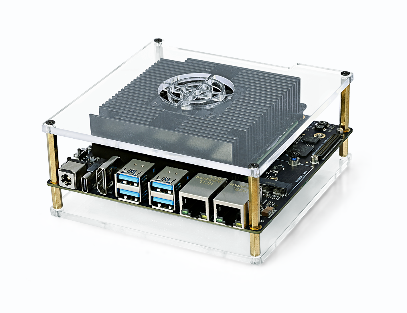
The D-Robotics RDK S100 Series Developer Kit is equipped with the S100 intelligent computing chip. Its BPU delivers up to 80/128 TOPS of computational power, making it a development board designed specifically for intelligent computing and robotics applications. Featuring a rich set of interfaces and exceptional ease of use, its unique heterogeneous architecture simultaneously addresses the demands of perception/inference and real-time motion control, thereby reducing the size and complexity of control systems.
Key Features
| Name | Specifications |
|---|---|
| Core Specs | CPU: 6x ARM® Cortex®-A78AE MCU: 4x ARM® Cortex®-R52+ (1× DCLS, 1× Split-Lock) BPU: 1x BPU Nash GPU: ARM Mali-G78AE RAM: 12/24GB 96-bit LPDDR5, Up to 6400 Mbps |
| Storage | Onboard 64GB eMMC M.2 Key M SSD interface provided |
| Connectivity | 4 x USB 3.0 Type-A ports 1 x USB 2.0 Type-C (for image flashing and MCU/Main Domain serial debugging) 1 x JTAG debugging interface (Main & MCU Domain) 1 x 40-Pin GPIO (SPI, I2C, I2S, PWM, UART, etc.) 1 x MCU expansion interface (for MCU Domain use) |
| Display | 1 x HDMI Type-A port, supporting up to 2560x1440@60Hz |
| Camera | 1 x camera expansion interface providing 3x 4-lane MIPI CSI-2 |
| Audio | 1 x I2S/PCM |
| Networking | 2 x RJ45 ports (Gigabit Ethernet) M.2 Key E (for Wi-Fi & BT modules) |
| Power | Power adapter: 90W adapter included in the package Power input: Board supports 12–20V DC, Max 150W |
| Temp Range | 32℉~113℉ |
Model Specifications
| Product Name | Model | SoC | CPU Frequency | Memory | BPU | Core Board Power Consumption |
|---|---|---|---|---|---|---|
| RDK S100 | KS1E55Y | S100E | 1.5GHz | 12GB LPDDR5 | 80 TOPS | Reference Power Consumption Data |
| RDK S100P | KS1P75Y | S100P | 2.0GHz | 24GB LPDDR5 | 128 TOPS | Reference Power Consumption Data |
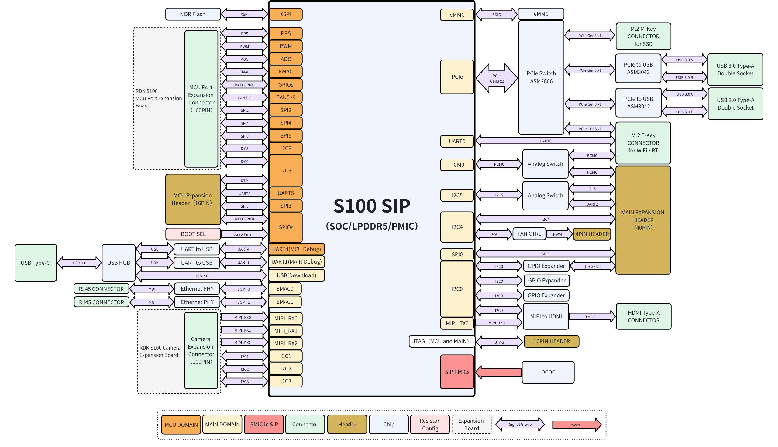
Architecture Diagram
Interface Diagram
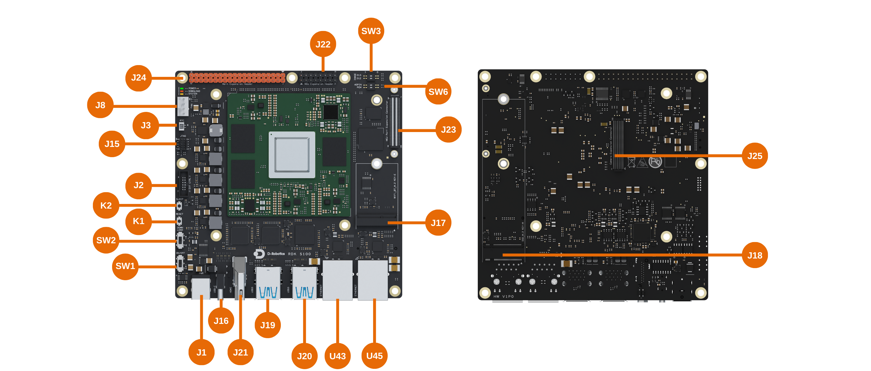
| No. | Function | No. | Function |
|---|---|---|---|
| J1 | DC Jack | J22 | MCU Expansion Header |
| J2 | Automatic EXT CTRL Connector | J23 | MCU Expansion Connector |
| J3 | RTC battery connector | J24 | Main Expansion Header |
| J8 | Fan connector | J25 | Camera Expansion Connector |
| J15 | JTAG interface for Main & MCU Domains | K1 | Reset button |
| J16 | Type-C port for flashing and debugging (Main & MCU Domains) | K2 | Sleep button |
| J17 | M.2 Key E Expansion Slot | SW1 | Power switch |
| J18 | M.2 Key M Expansion Slot | SW2 | DFU Flashing mode |
| J19&J20 | USB Interfaces | SW3&SW6 | DIP Switches |
| J21 | HDMI interface | U43&U45 | Wired Ethernet Ports |
Wi-Fi and SSD Installation
Installation must be performed only when the development board is powered off and the DC plug is disconnected.
Interface Descriptions
Pinout Definition: drobotics_rdk_s100_pinlist_v1p0.xlsx
DC Jack (J1)
Rated voltage: 20V, rated current: 10A. The S100 mainboard accepts input power from 12–20V DC. Use a power adapter with inner diameter 2.5mm and outer diameter 6mm to power the S100 system.
Automatic EXT CTRL Connector (J2)
The RDK S100 mainboard includes a 12-Pin Automatic EXT CTRL Connector, primarily serving the following purposes:
- Extends system status LEDs (power and operational indicators) to the exterior of the mainboard for easy status monitoring.
- Extends physical controls (flash switch, sleep button, reset button, and power switch) to the exterior for convenient manual operation after system integration.
- The green LED indicates whether the mainboard’s minimal system has completed power-up; the orange LED indicates whether the Main Domain system is operating normally.
- The 12-Pin Automatic EXT CTRL Connector may only be connected to circuits described in its functional specification. High-power loads are strictly prohibited.
- When the system is in light sleep or deep sleep mode, VDD_AON_PERI_5V and DCIN_CONN remain powered, while VDD_PERI_3V3 is turned off. External daughterboards must include short-circuit protection to prevent abnormal power behavior due to shorts.
- Maximum output current for VDD_AON_PERI_5V, DCIN_CONN, and VDD_PERI_3V3 is 50mA, 5mA, and 100mA, respectively.
RTC battery connector (J3)
The commercial version offers more comprehensive feature support, deeper hardware access, and exclusive customization options. To ensure compliant and secure delivery, access to the commercial version will be granted through the following process:
Commercial Version Access Procedure:
- Complete a questionnaire: Submit basic information about your organization and intended use case.
- Sign an NDA: We will contact you based on your submission to finalize and sign a Non-Disclosure Agreement.
- Content release: After NDA execution, commercial documentation will be provided via a private channel.
If you wish to access the commercial version, please complete the questionnaire below. We will contact you within 3–5 business days:
Questionnaire link: https://horizonrobotics.feishu.cn/share/base/form/shrcnJQBMIkRm6K79rjXR0hr0Fg
FAN Connector (J8)
The FAN Connector is used to connect a cooling fan and supports fan speed control.
- Maximum 12V supply current is 200mA. When the system is in light sleep or deep sleep mode, the VDD_PERI_12V power rail is turned off.
Type-C port for flashing and debugging (Main & MCU Domains) (J16)
The USB Type-C port (J16) is intended solely for flashing and debugging—it is not a standard full-featured USB Type-C port. It provides the following functions:
-
Debug UART: Two
CH340chips convert the debug UARTs from both the Main Domain and MCU Domain of the core module into USB interfaces, enabling various debugging tasks. On first use, install the CH340 driver on your host computer by searching for "CH340 serial driver." Configure your serial terminal with the following settings:- Baud rate: 921600
- Data bits: 8
- Parity: None
- Stop bits: 1
- Flow control: None
-
USB Download Interface: This port serves as a firmware download interface. For details, refer to 1.2 System Flashing.
The USB Type-C port on the RDK S100 development board supports Device mode only.
M.2 Key E Expansion Slot (J17)
By default, this slot connects to PCIe-based Wi-Fi and 4-wire UART Bluetooth modules. It supports PCIe Gen3 x1 but does not provide USB or SDIO interfaces, nor does it support LED or ALERT signals.
- For Wi-Fi/Bluetooth wake-from-sleep functionality, please contact D-Robotics engineers for support.
- When the system is in light sleep or deep sleep mode, VDD_AON_PERI_3V3 remains powered, with a maximum output current of 750mA.
M.2 Key M Expansion Slot (J18)
Used for connecting PCIe solid-state drives (SSDs). Supports PCIe Gen3 x1, includes an ALERT signal, but no LED signal.
- Wake-from-sleep functionality is not supported.
- I2C4 is already assigned by default to the M.2 Key M interface, RTC IC, and fan speed control IC. The I2C addresses (excluding R/W bit) for the RTC IC and fan control IC are 0x32 and 0x2F, respectively.
- When the system is in light sleep or deep sleep mode, VDD_PERI_3V3 is turned off, with a maximum output current of 700mA.
MCU Expansion Header (J22)
The RDK S100 mainboard includes a 16-pin MCU Expansion Header (hereafter referred to as the 16-Pin Header), providing:
- Power signals: VDD_AON_PERI_MCU_3V3, VDD_AON_PERI_MCU_5V
- Communication interfaces:
- I2C9 (with 3.2kΩ pull-up resistors populated on the board)
- SPI3- UART5
- PWM signals: PWM6, PWM7.
- GPIO signals: GPIO_MCU_36_3V3, GPIO_MCU_37_3V3.
- When the system is in light sleep or deep sleep mode, the power supplies VDD_AON_PERI_MCU_3V3 and VDD_AON_PERI_MCU_5V remain powered, with maximum output currents of 300mA and 200mA, respectively.
- When GPIO_MCU_36_3V3 and GPIO_MCU_37_3V3 on the 16-Pin Header are connected to peripherals, the corresponding peripheral pins must be held low by default upon power-up.
- When the I2C9_SDA_3V3 and I2C9_SCL_3V3 signals are used as GPIOs, external pull-down resistors must not be connected.
MCU Expansion Connector (J23)
The RDK S100 mainboard includes a 100-pin expansion connector named the MCU Expansion Connector, hereinafter referred to as the MCU 100-Pin Connector.
- Power signals: VDD_AON_PERI_MCU_5V, VDD_AON_PERI_MCU_3V3, VDDIO_MCU_3V3, VDDIO_MCU_1V8.
- Network interface: EMAC RGMII interface signals.
- Communication interfaces:
- I2C8, with an equivalent 4.7kΩ pull-up resistor configured on the mainboard.
- I2C9, with an equivalent 3.2kΩ pull-up resistor configured on the mainboard.
- SPI2, SPI4, SPI5
- CAN interfaces: CAN5, CAN6, CAN7, CAN8, CAN9
- Other signals: GPIO, PWM, ADC signals.
- The MCU 100-Pin Connector includes I/Os operating at both 1.8V and 3.3V logic levels. For details, refer to the Pin Definition document.
- When the following 14 I/Os on the MCU 100-Pin Connector are connected to peripherals, the default high/low state of the corresponding peripheral pins upon power-up must match the Pull Up/Down configuration specified in the Pin Definition document: SPI5_CSN1_3V3, GPIO_MCU_36_3V3, GPIO_MCU_37_3V3, GPIO_MCU_35_3V3, SPI5_MOSI_3V3, GPIO_MCU_9_3V3, CAN5_TX_3V3, CAN6_TX_3V3, CAN9_TX_3V3, CAN8_TX_3V3, SPI5_CSN0_3V3, CAN7_TX_3V3, GPIO_MCU_6_3V3, GPIO_MCU_7_3V3.
- When the system is in light sleep or deep sleep mode, VDD_AON_PERI_MCU_5V and VDD_AON_PERI_MCU_3V3 remain powered, each with a maximum output current of 1000mA.
- VDDIO_MCU_3V3 and VDDIO_MCU_1V8 each have a maximum output current of 50mA and are intended only for low-power applications such as level shifting, pull-up/pull-down resistors, and ADC voltage dividers. These supplies remain powered in light sleep mode but are turned off in deep sleep mode.
Main Expansion Header (J24)
The RDK S100 mainboard includes a 40-pin expansion header named the Main Expansion Header, hereinafter referred to as the 40-Pin Header.
- Power signals: VDD_PERI_3V3, VDD_PERI_5V.
- Communication interfaces:
- I2C5, with a 4kΩ pull-up resistor configured on the mainboard.
- UART2, with a 4kΩ pull-up resistor configured on the mainboard.
- SPI0, supporting master mode only.
- LPWM (GPIO_CAM_4_3V3 and GPIO_CAM_5_3V3).
- Audio interface: PCM0-related signals are shared with the Wi-Fi module’s PCM interface.
- GPIO signals: 10 GPIOs labeled 40PIN_GPIO0_3V3 through 40PIN_GPIO9_3V3, provided by a GPIO expander IC with internal 100kΩ pull-up resistors by default.
- I2C4 is by default used for communication with the M.2 KEY M interface, RTC IC, and fan speed control IC. The I2C addresses (excluding R/W bit) of the RTC IC and fan speed control IC are 0x32 and 0x2F, respectively.
- I2C5 and UART2 share the same pins. The PCM0 interface is shared between the 40-Pin Header and the M.2 KEY E connector and can be switched via DIP switch SW6.
- When the system is in light sleep or deep sleep mode, VDD_PERI_3V3 and VDD_PERI_5V are turned off. Both supplies have a maximum output current of 1000mA.
- When used as GPIOs, the signals I2C4_SDA_3V3, I2C4_SCL_3V3, I2C5_SDA_3V3, I2C5_SCL_3V3, UART2_TX_3V3, and UART2_RX_3V3 must not be connected to external pull-down resistors.
Camera Expansion Connector (J25)
The RDK S100 mainboard includes a 100-pin expansion connector named the Camera Expansion Connector, hereinafter referred to as the CAM 100-Pin Connector.
- Power signals: VDD_PERI_3V3, VDD_PERI_12V, VDDIO_TOP_1V8.
- Image interfaces: 3 sets of 4-lane MIPI RX signals.
- Communication interfaces:
- I2C1, with an equivalent 4.7kΩ pull-up resistor configured on the mainboard.
- I2C2, with an equivalent 4.7kΩ pull-up resistor configured on the mainboard.
- I2C3, with an equivalent 2.2kΩ pull-up resistor configured on the mainboard.
- Other signals: LPWM signals, ADC sensing signals, Camera Board ID signals, GPIO signals, etc.
- The CAM 100-Pin Connector includes I/Os operating at both 1.8V and 3.3V logic levels. For details, refer to the Pin Definition document.
- The VDDIO_TOP_1V8 power supply has a maximum output current of 50mA and is intended only for low-power applications such as level shifting, pull-up/pull-down resistors, and ADC voltage dividers.
- When the system is in light sleep or deep sleep mode, VDD_PERI_3V3, VDD_PERI_12V, and VDDIO_TOP_1V8 are turned off. The maximum output currents are 1700mA for the 3.3V supply and 800mA for the 12V supply.
Wired Ethernet Ports (U43/U45)
The development board features two Gigabit Ethernet ports compatible with 1000BASE-T and 100BASE-T standards, supporting auto-negotiation for speed switching.
| ID | Label | Function Description | IP Configuration Method | Default IP Address |
|---|---|---|---|---|
| U43 | eth0 | General-purpose Ethernet port; user-configured IP address | External DHCP or manual static | None |
| U45 | eth1 | Management or dedicated communication port; built-in static IP | Fixed static IP | 192.168.127.10 |
HDMI Interface (J21)
The RDK S100 development board provides one HDMI display interface supporting up to 2K@60fps resolution. After power-up, the board outputs the Ubuntu graphical interface via HDMI and, with specific example applications, also supports preview display of camera and video stream content.
USB Interfaces (J19/J20)
The RDK S100 development board provides four USB 3.0 standard ports expanded via PCIe, supporting simultaneous connection of four USB peripherals. Each USB 3.0 port supports a maximum output power of 5V/1A.
- The USB 3.0 ports on the RDK S100 development board support Host mode only.
- Note the USB 2.0 camera connection capability limitations.
Switches, Buttons, and LED Indicators
Buttons (K1/K2)
| ID | Name | Description | Usage |
|---|---|---|---|
| K1 | RESET | Resets the S100 system | Press to reset the system |
| K2 | SLEEP | Puts the S100 system into sleep or wakes it | Single press triggers sleep/wake interrupt |
Switches (SW1/SW2)
| ID | Name | Description | Usage |
|---|---|---|---|
| SW1 | ON/OFF | Power switch | ▽: ON, ↑: OFF |
| SW2 | DOWNLOAD | DFU flashing mode | ▽: Normal boot mode, ↑: DFU mode |
DIP Switches (SW3/SW6)
Boot Device Selection (SW3)
Currently, only eMMC boot is supported.
| D13 | D12 | Boot Medium | Description |
|---|---|---|---|
| 0 | 1 | eMMC | Boot from onboard eMMC |
| 1 | 0 | NVMe | Boot from M.2 NVMe SSD |
Function Selection (SW6)
On the 40-Pin Header, I2C5 and UART2 share pins. Additionally, the PCM0 interface is shared between the 40-Pin Header (J24) and the M.2 KEY E connector (J17), and can be switched using DIP switch SW6.
For PCM0, if Bluetooth audio functionality from the Wi-Fi module is not required, set the DIP switch to the right position by default.
| DIP Label | 1 | 0 |
|---|---|---|
| 40 PIN | Pins 3 and 5 active as I2C5 | Pins 8 and 10 active as UART2 |
| PCM0 | PCM0 assigned to M.2 KEY E | PCM0 assigned to 40PIN |
Status LEDs
The RDK S100 mainboard features three LEDs—POWER, DOWNLOAD, and SYSTEM—next to connector J8, indicating mainboard power status, DFU flashing mode, and system operational status, respectively.
POWER (Green)
| Status | Description |
|---|---|
| On | Power ON |
| Off | Power OFF |
DOWNLOAD (Red)
| Status | Description |
|---|---|
| On | Entered DFU mode |
| Off | Normal boot mode |
SYSTEM (Amber)
| Status | Description |
|---|---|
| Blinking | System running normally |
| Steady On / Off | System abnormal |
Connector Part Numbers
| Connector | Part Number | Manufacturer |
|---|---|---|
| J1 | DC-044B-D025 | G-Switch |
| J2 | HX JN1.27-2x6P ZZ H4.9 | Hanxia |
| J3 | HDGC1002WV-S-2P | Huade Co-create Technology |
| J8 | 470531000 | Molex |
| J15 | 356-110A0CMBB1 | Guangdezhong Electronics |
| J16 | XUBF-0316-FS458 | Lianxin Tech |
| J17 | APCI0108-P001A | Lianxin Tech |
| J18 | APCI0079-P002A | Lianxin Tech |
| J22 | PZ254V-12-16P | XFCN |
| J23 | HC-PBB05-2-100-F-H2.2-G1-R-P-04 | Huacan Tianlu |
| J24 | 313240SK24011160A4P | Lianxiang Electronics |
| J25 | HC-PBB05-2-100-F-H4.0-G1-R-P-04 | Huacan Tianlu |