3.4.2 参考示例(C++)
本章节介绍多媒体库开发的多种功能示例,包括摄像头图像采集、视频编解码、视频显示、算法推理等功能。
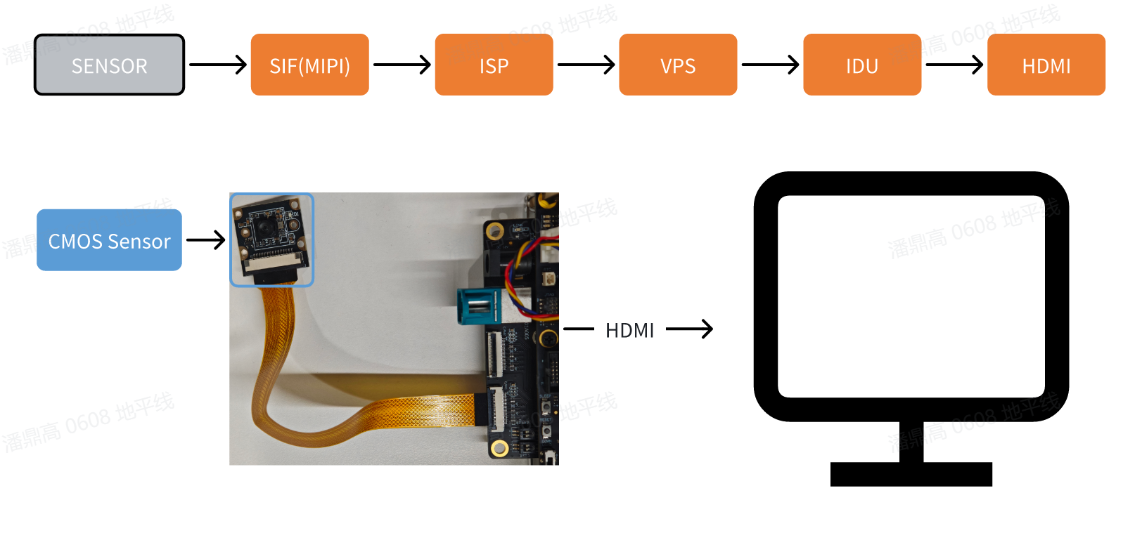
摄像头图像采集和显示
本示例vio2display示例实现了MIPI摄像头图像采集功能,并通过HDMI接口输出,用户可通过显示器预览画面。
示例流程框图:
-
环境准备:
- 开发板断电状态下,将
MIPI摄像头接入开发板,目前该sample仅支持MIPI sensor: IMX219, SC230AI - 通过 HDMI 线缆连接开发板和显示器
- 开发板上电,并通过命令行登录
- 开发板断电状态下,将
-
运行方式: 示例代码以源码形式提供,需要使用
make命令进行编译后运行,步骤如下:sunrise@ubuntu:~$ cd /app/cdev_demo/vio2display
sunrise@ubuntu:/app/cdev_demo/vio2display$ make
sunrise@ubuntu:/app/cdev_demo/vio2display$ ./vio2display -w 1920 -h 1080参数说明:
- -w: sensor 输出宽度
- -h: sensor 输出高度
-
预期效果: 程序正确运行后,开发板会通过显示器输出
MIPI摄像头采集的实时画面。运行 log 如下:sunrise@ubuntu:/app/cdev_demo/vio2display$ ./vio2display -w 1920 -h 1080
[UCP]: log level = 3
[UCP]: UCP version = 3.7.3
[VP]: log level = 3
[DNN]: log level = 3
[HPL]: log level = 3
[UCPT]: log level = 6
disp_w=1920, disp_h=1080
2025/06/16 10:12:21.574 !INFO [CamInitParam][0295]set camera fps: -1,width: 1920,height: 1080
mipi mclk is not configed.
Searching camera sensor on device: /proc/device-tree/soc/vcon@0 i2c bus: 1 mipi rx phy: 0
WARN: Sensor Name: ar0820std-30fps, Expected Chip ID: 0xCB34, Actual Chip ID Read: 0x00
[0] INFO: Found sensor name:imx219-30fps on mipi rx csi 0, i2c addr 0x10, config_file:linear_1920x1080_raw10_30fps_1lane.c
2025/06/16 10:12:21.575 !INFO [CamInitPymParam][0258]Setting PYM channel:0: crop_x:0, crop_y:0, input_width:1920, input_height:1080, dst_w:1920, dst_h:1080
sp_open_camera success!
2025/06/16 10:12:21.727 !INFO [OpenDisplay][0111]Wayland is available, using Wayland for rendering.
Using default socket path: /run/user/1000/wayland-0
Press 'q' to Exit !
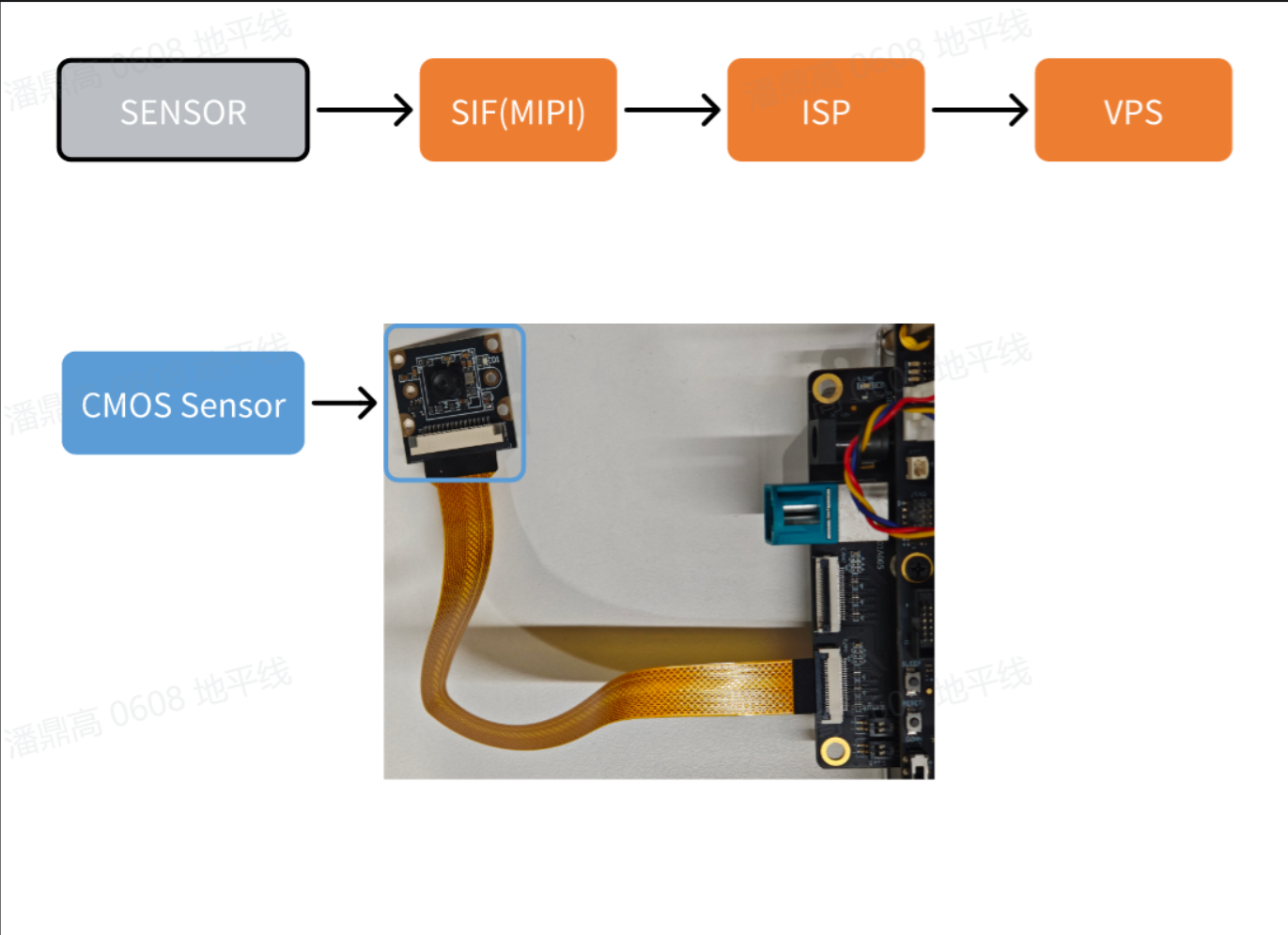
摄像头图像本地保存
本示例vio_capture示例实现了MIPI摄像头图像采集,并将RAW和YUV两种格式的图像本地保存的功能。示例流程框图如下:
示例流程框图:
-
环境准备:
- 开发板断电状态下,将
MIPI摄像头接入开发板, 目前该sample仅支持MIPI sensor: IMX219, SC230AI - 开发板上电,并通过命令行登录
- 开发板断电状态下,将
-
运行方式: 示例代码以源码形式提供,需要使用
make命令进行编译后运行,步骤如下:sunrise@ubuntu:~$ cd /app/cdev_demo/vio_capture/
sunrise@ubuntu:/app/cdev_demo/vio_capture$ make
sunrise@ubuntu:/app/cdev_demo/vio_capture$ ./capture -b 10 -c 10 -w 1920 -h 1080参数说明:
- -b: RAW图bit数,例如IMX219支持格式为RAW10,则bit数为10。sensor支持格式可参考配�件清单
- -c: 保存图像的数量,获取到每张图像的时间间隔一般为1/fps
- -w: 保存图像的宽度
- -h: 保存图像的高度
-
预期效果: 程序正确运行后,当前目录保存指定数量的图片文件,
RAW格式以raw_*.raw方式命名,YUV格式以yuv_*.yuv方式命名。运行log如下:sunrise@ubuntu:/app/cdev_demo/vio_capture$ ./capture -b 10 -c 10 -w 1920 -h 1080
[UCP]: log level = 3
[UCP]: UCP version = 3.7.3
[VP]: log level = 3
[DNN]: log level = 3
[HPL]: log level = 3
[UCPT]: log level = 6
2025/06/04 22:24:22.139 !INFO [CamInitParam][0296]set camera fps: -1,width: 1920,height: 1080
mipi mclk is not configed.
Searching camera sensor on device: /proc/device-tree/soc/vcon@0 i2c bus: 1 mipi rx phy: 0
WARN: Sensor Name: ar0820std-30fps, Expected Chip ID: 0xCB34, Actual Chip ID Read: 0x00
[0] INFO: Found sensor name:imx219-30fps on mipi rx csi 0, i2c addr 0x10, config_file:linear_1920x1080_raw10_30fps_1lane.c
2025/06/04 22:24:22.140 !INFO [CamInitPymParam][0259]Setting PYM channel:0: crop_x:0, crop_y:0, input_width:1920, input_height:1080, dst_w:1920, dst_h:1080
capture time :0
temp_ptr.data_size[0]:2592000
... 省略 ...
capture time :9
temp_ptr.data_size[0]:2592000
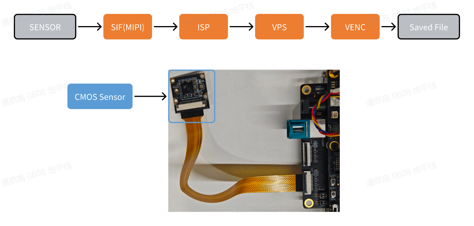
摄像头图像采集并编码
本示例vio2encoder示例实现了 MIPI 摄像头图像采集功能,并编码后在本地保存
示例流程框图:
-
环境准备:
- 开发板断电状态下,将
MIPI摄像头接入开发板, 目前该sample仅支持MIPI sensor: IMX219, SC230AI - 开发板上电,并通过命令行登录
- 开发板断电状态下,将
-
运行方式: 按照以下命令执行程序 示例代码以源码形式提供,需要使用
make命令进行编译后运行,步骤如下:sunrise@ubuntu:~$ cd /app/cdev_demo/vio2encoder
sunrise@ubuntu:/app/cdev_demo/vio2encoder$ make
sunrise@ubuntu:/app/cdev_demo/vio2encoder$ ./vio2encoder -w 1920 -h 1080 --iwidth 1920 --iheight 1080 -o stream.h264参数说明:
- -w: 编码视频宽度
- -h: 编码视频高度
- --iwidth: sensor 输出宽度
- --iheight: sensor 输出高度
- -o: 编码输出路径
-
预期效果: 程序正确运行后,在当前目录下会生成名为
stream.h264的视频文件。运行 log 如下:sunrise@ubuntu:/app/cdev_demo/vio2encoder$ ./vio2encoder -w 1920 -h 1080 --iwidth 1920 --iheight 1080 -o stream.h264
[UCP]: log level = 3
[UCP]: UCP version = 3.7.3
[VP]: log level = 3
[DNN]: log level = 3
[HPL]: log level = 3
[UCPT]: log level = 6
2025/06/16 11:04:37.628 !INFO [CamInitParam][0295]set camera fps: -1,width: 1920,height: 1080
mipi mclk is not configed.
Searching camera sensor on device: /proc/device-tree/soc/vcon@0 i2c bus: 1 mipi rx phy: 0
WARN: Sensor Name: ar0820std-30fps, Expected Chip ID: 0xCB34, Actual Chip ID Read: 0x00
[0] INFO: Found sensor name:imx219-30fps on mipi rx csi 0, i2c addr 0x10, config_file:linear_1920x1080_raw10_30fps_1lane.c
2025/06/16 11:04:37.629 !INFO [CamInitPymParam][0258]Setting PYM channel:0: crop_x:0, crop_y:0, input_width:1920, input_height:1080, dst_w:1920, dst_h:1080
sp_open_camera success!
2025/06/16 11:04:37.770 !INFO [vp_encode_config_param][0408]codec type is h264: frame size:3110912 frame rate: 30
sp_start_encode success!
sp_module_bind(vio -> encoder) success!
^C
recv:2,Stoping...
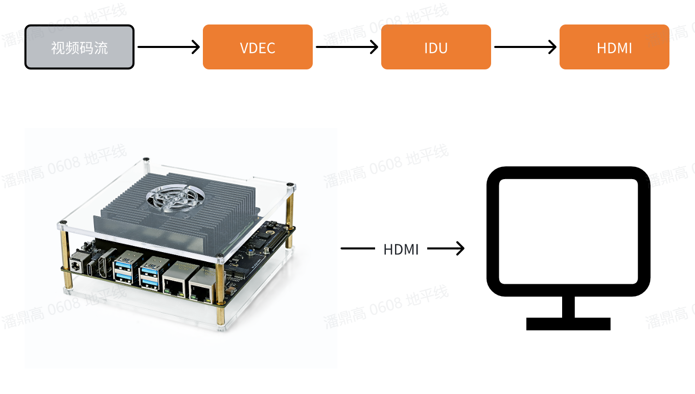
视频文件解码并显示
本示例decoder2display实现了视频文件解码,并通过HDMI接口输出,用户可通过显示器预览画面。
示例流程框图:
-
环境准备:
- 通过 HDMI 线缆连接开发板和显示器
- 开发板上电,并通过命令行登录
- 准备视频编码文件
stream.h264作为输入。
-
运行方式: 示例代码以源码形式提供,需要使用
make命令进行编译后运行,步骤如下:sunrise@ubuntu:~$ cd /app/cdev_demo/decode2display
sunrise@ubuntu:/app/cdev_demo/decode2display$ make
sunrise@ubuntu:/app/cdev_demo/decode2display$ ./decoder2display -w 1920 -h 1080 -i /app/res/assets/1080P_test.h264参数说明:
- -h: 视频文件的高度
- -w: 视频文件的宽度
- -i: 视频文件的路径
-
预期效果: 程序正确运行后,视频画面会通过开发板的
HDMI接口输出,用户可以通过显示器预览视频画面。运行 log 如下:sunrise@ubuntu:/app/cdev_demo/decode2display$ ./decoder2display -w 1920 -h 1080 -i /app/res/assets/1080P_test.h264
[UCP]: log level = 3
[UCP]: UCP version = 3.7.3
[VP]: log level = 3
[DNN]: log level = 3
[HPL]: log level = 3
[UCPT]: log level = 6
disp_w=1920, disp_h=1080
sp_start_decode success!
2025/06/16 10:48:49.220 !WARN [sp_start_display][0049]Warning: Using vot_chn values 0-3 is deprecated. Defaulting to HDMI mode.
2025/06/16 10:48:49.221 !WARN [sp_start_display][0050]Please use the new method: pass 10 for DisplayPort (DP) or 11 for HDMI.
2025/06/16 10:48:49.221 !INFO [OpenDisplay][0111]Wayland is available, using Wayland for rendering.
Using default socket path: /run/user/1000/wayland-0
sp_start_display success!
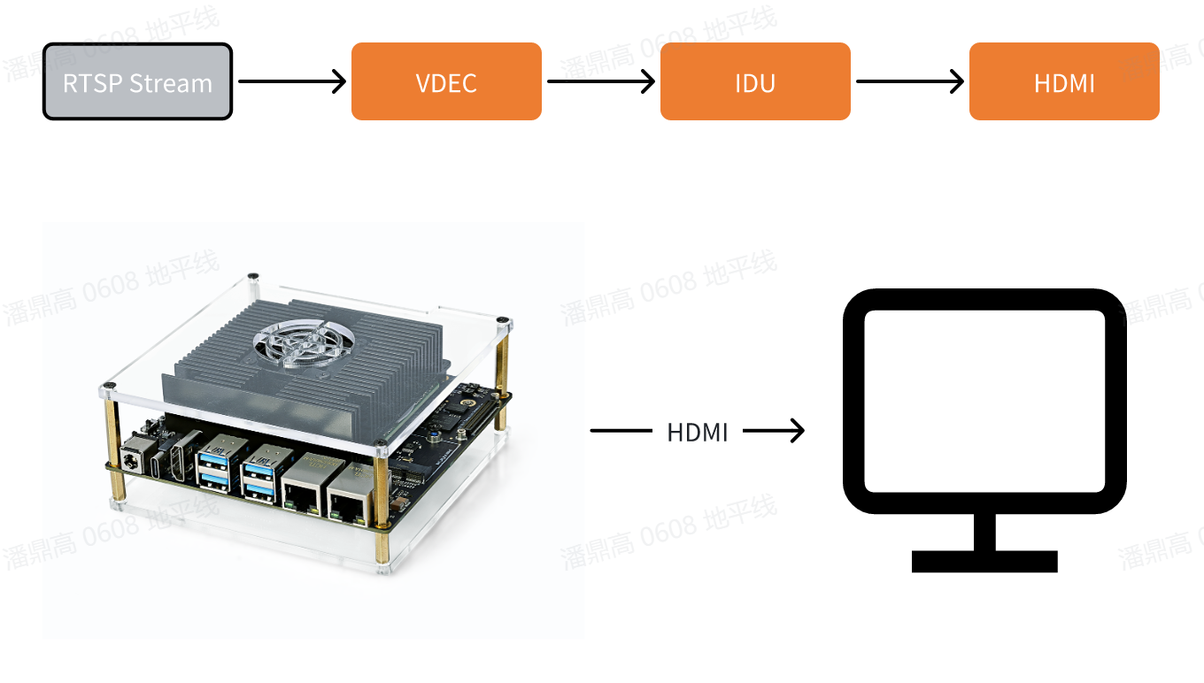
RTSP 拉流解码
本示例rtsp2display实现了拉取rtsp码流、解码,并通过HDMI输出视频图像的功能,用户可通过显示器预览画面。
示例流程框图:
-
环境准备:
-
通过 HDMI 线缆连接开发板和显示器
-
开发板上电,并通过命令行登录
-
准备
rtsp码流作为输入源,使用系统预置的推流服务。该服务会把1080P_test.h264视频文件处理成 rtsp 流,url 地址为rtsp://127.0.0.1/assets/1080P_test.h264。用户可通过如下命令启动推流服务:cd /app/res
sunrise@ubuntu:/app/res# sudo chmod +x live555MediaServer
sunrise@ubuntu:/app/res# sudo ./live555MediaServer &
-
-
运行方式: 示例代码以源码形式提供,需要使用
make命令进行编译后运行,步骤如下:sunrise@ubuntu:~$ cd /app/cdev_demo/rtsp2display
sunrise@ubuntu:/app/cdev_demo/rtsp2display$ make #可能会打印一些警告信息,无需理会
sunrise@ubuntu:/app/cdev_demo/rtsp2display$ ./rtsp2display -i rtsp://127.0.0.1/assets/1080P_test.h264 -t tcp参数配置:
- -i: 码流 url 地址
- -t: 传输类型,可选 tcp / udp
-
预期效果: 程序正确运行后,视频画面会通过开发板的
HDMI接口输出,用户可以通过显示器预览视频画面。运行 log 如下:sunrise@ubuntu:/app/cdev_demo/rtsp2display$ ./rtsp2display -i rtsp://127.0.0.1/assets/1080P_test.h264 -t tcp
[UCP]: log level = 3
[UCP]: UCP version = 3.7.3
[VP]: log level = 3
[DNN]: log level = 3
[HPL]: log level = 3
[UCPT]: log level = 6
avformat_open_input ok!
avformat_find_stream_info ok!
Input #0, rtsp, from 'rtsp://127.0.0.1/assets/1080P_test.h264':
Metadata:
title : H.264 Video, streamed by the LIVE555 Media Server
comment : 1080P_test.h264
Duration: N/A, start: 0.040000, bitrate: N/A
Stream #0:0: Video: h264 (High), yuv420p(progressive), 1920x1080 [SAR 1:1 DAR 16:9], 25 fps, 25 tbr, 90k tbn, 50 tbc
av_dump_format ok!
rtsp_w:1920,rtsp_h:1080
display_w:1920,dispaly_h:1080
2025/06/16 10:57:21.724 !WARN [sp_start_display][0049]Warning: Using vot_chn values 0-3 is deprecated. Defaulting to HDMI mode.
2025/06/16 10:57:21.724 !WARN [sp_start_display][0050]Please use the new method: pass 10 for DisplayPort (DP) or 11 for HDMI.
2025/06/16 10:57:21.724 !INFO [OpenDisplay][0111]Wayland is available, using Wayland for rendering.
Using default socket path: /run/user/1000/wayland-0
2025/06/16 10:57:21.793 !INFO [CamInitPymParam][0258]Setting PYM channel:0: crop_x:0, crop_y:0, input_width:1920, input_height:1080, dst_w:1920, dst_h:1080
sp_open_vps success!
Could not read frame ---(error 'End of file') -
注意事项:
- 使用 UDP 协议传输码流时,可能出现因网络丢包导致的花屏现象,此时可切换成 TCP 协议传输解决;
- 若使用上述命令有Connection refused报错,则上述命令中
127.0.0.1部分可能需要根据live555MediaServer执行时打印出来的服务器实际运行端口,添加端口信息,例如:# final output of live555MediaServer
...
(We use port 8000 for optional RTSP-over-HTTP tunneling, or for HTTP live streaming (for indexed Transport Stream files only).)
...
# rtsp2display actual command
sunrise@ubuntu:/app/cdev_demo/rtsp2display$ ./rtsp2display -i rtsp://127.0.0.1:8000/assets/1080P_test.h264 -t tcp
VPS 缩放示例
本示例实现了基于视频处理模块VPS的视频缩放功能, 可截取视频文件其中一帧进行缩小处理,或缩小指定图片
-
环境准备:
- 开发板上电,并通过命令行登录
- 准备图像(NV12)、视频文件(H264)作为输入
-
运行方式: 示例代码以源码形式提供,需要使用
make命令进行编译后运行,步骤如下:sunrise@ubuntu:~$ cd /app/cdev_demo/vps
sunrise@ubuntu:/app/cdev_demo/vps$ make
sunrise@ubuntu:/app/cdev_demo/vps$ ./vps -m 1 -i input_1080p.h264 -o output1.yuv --iheight 1080 --iwidth 1920 --oheight 720 --owidth 1280
sunrise@ubuntu:/app/cdev_demo/vps$ ./vps -m 2 -i input_1080p.yuv -o output.yuv --iheight 1080 --iwidth 1920 --oheight 720 --owidth 1280参数配置:
- -i: 待操作的文件路径
- --iheight: 输入高度
- --iwidth: 输入宽度
- -m: 输入模式,1:视频流;2:NV12 图片
- -o: 输出路径
- --oheight: 输出高度
- --owidth: 输出宽度
- --skip:(可选)对于视频流输入,调过开头的帧数
-
预期效果: 程序正确运行后,当前目录会保存处理后的图像文件
outpu.yuv。运行 log 如下:sunrise@ubuntu:/app/cdev_demo/vps$ ./vps -m 1 -i input_1080p.h264 -o output1.yuv --iheight 1080 --iwidth 1920 --oheight 720 --owidth 1280
[UCP]: log level = 3
[UCP]: UCP version = 3.7.3
[VP]: log level = 3
[DNN]: log level = 3
[HPL]: log level = 3
[UCPT]: log level = 6
2025/06/16 10:33:02.709 !INFO [CamInitPymParam][0258]Setting PYM channel:0: crop_x:0, crop_y:0, input_width:1920, input_height:1080, dst_w:1280, dst_h:720
sunrise@ubuntu:/app/cdev_demo/vps$ ./vps -m 2 -i input_1080p.yuv -o output.yuv --iheight 1080 --iwidth 1920 --oheight 720 --owidth 1280
[UCP]: log level = 3
[UCP]: UCP version = 3.7.3
[VP]: log level = 3
[DNN]: log level = 3
[HPL]: log level = 3
[UCPT]: log level = 6
2025/06/16 10:33:29.134 !INFO [CamInitPymParam][0258]Setting PYM channel:0: crop_x:0, crop_y:0, input_width:1920, input_height:1080, dst_w:1280, dst_h:720
... 省略 ...