3.4.2 Reference Examples (C++)
This section introduces multiple functional examples for multimedia library development, including camera image capture, video encoding/decoding, video display, algorithm inference, and other features.
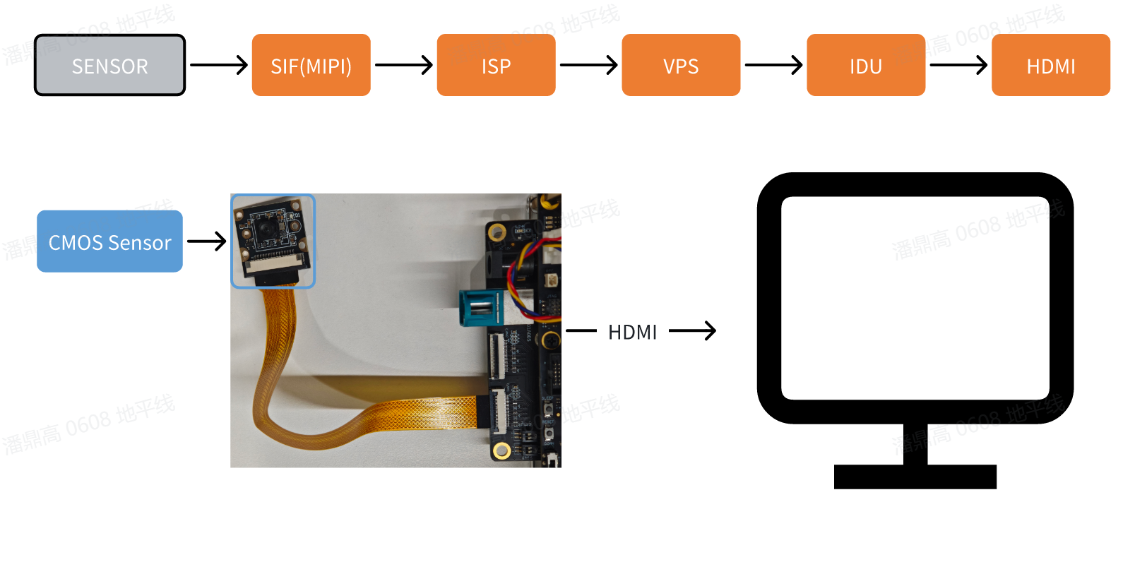
Camera Image Capture and Display
The vio2display example implements image capture from a MIPI camera and outputs the video via an HDMI interface, allowing users to preview the live feed on a monitor.
Example flow diagram:
-
Environment Setup:
- With the development board powered off, connect the
MIPIcamera to the board. Currently, this sample only supports MIPI sensors: IMX219, SC230AI. - Connect the development board to a monitor using an HDMI cable.
- Power on the development board and log in via the command line.
- With the development board powered off, connect the
-
Execution Method: The example code is provided in source form and must be compiled using the
makecommand before running. Follow these steps:sunrise@ubuntu:~$ cd /app/cdev_demo/vio2display
sunrise@ubuntu:/app/cdev_demo/vio2display$ make
sunrise@ubuntu:/app/cdev_demo/vio2display$ ./vio2display -w 1920 -h 1080Parameter descriptions:
-w: Sensor output width-h: Sensor output height
-
Expected Result: After successful execution, the development board outputs the real-time video captured by the
MIPIcamera to the connected monitor. Sample log output:sunrise@ubuntu:/app/cdev_demo/vio2display$ ./vio2display -w 1920 -h 1080
[UCP]: log level = 3
[UCP]: UCP version = 3.7.3
[VP]: log level = 3
[DNN]: log level = 3
[HPL]: log level = 3
[UCPT]: log level = 6
disp_w=1920, disp_h=1080
2025/06/16 10:12:21.574 !INFO [CamInitParam][0295]set camera fps: -1,width: 1920,height: 1080
mipi mclk is not configed.
Searching camera sensor on device: /proc/device-tree/soc/vcon@0 i2c bus: 1 mipi rx phy: 0
WARN: Sensor Name: ar0820std-30fps, Expected Chip ID: 0xCB34, Actual Chip ID Read: 0x00
[0] INFO: Found sensor name:imx219-30fps on mipi rx csi 0, i2c addr 0x10, config_file:linear_1920x1080_raw10_30fps_1lane.c
2025/06/16 10:12:21.575 !INFO [CamInitPymParam][0258]Setting PYM channel:0: crop_x:0, crop_y:0, input_width:1920, input_height:1080, dst_w:1920, dst_h:1080
sp_open_camera success!
2025/06/16 10:12:21.727 !INFO [OpenDisplay][0111]Wayland is available, using Wayland for rendering.
Using default socket path: /run/user/1000/wayland-0
Press 'q' to Exit !
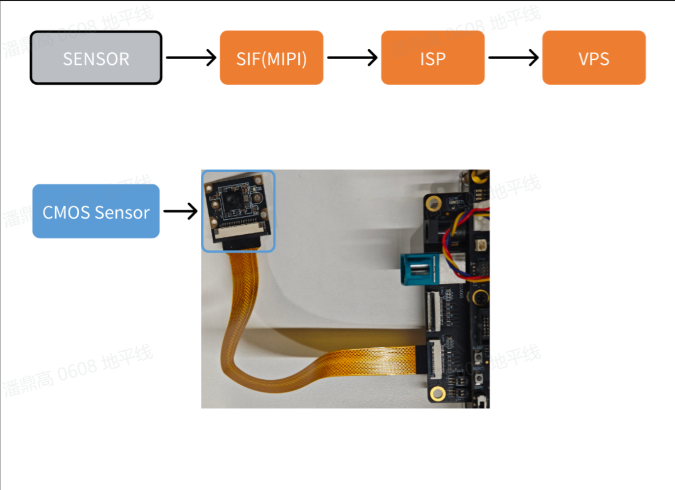
Local Saving of Camera Images
The vio_capture example captures images from a MIPI camera and saves them locally in both RAW and YUV formats. The example flow diagram is as follows:
Example flow diagram:
-
Environment Setup:
- With the development board powered off, connect the
MIPIcamera to the board. Currently, this sample only supports MIPI sensors: IMX219, SC230AI. - Power on the development board and log in via the command line.
- With the development board powered off, connect the
-
Execution Method: The example code is provided in source form and must be compiled using the
makecommand before running. Follow these steps:sunrise@ubuntu:~$ cd /app/cdev_demo/vio_capture/
sunrise@ubuntu:/app/cdev_demo/vio_capture$ make
sunrise@ubuntu:/app/cdev_demo/vio_capture$ ./capture -b 10 -c 10 -w 1920 -h 1080Parameter descriptions:
-b: Bit depth of the RAW image. For example, IMX219 supports RAW10 format, so the bit depth is 10. Refer to the Accessory List for supported sensor formats.-c: Number of images to save. The interval between capturing each image is typically 1/fps.-w: Width of the saved images-h: Height of the saved images
-
Expected Result: After successful execution, the specified number of image files are saved in the current directory. RAW format files are named
raw_*.raw, and YUV format files are namedyuv_*.yuv. Sample log output:sunrise@ubuntu:/app/cdev_demo/vio_capture$ ./capture -b 10 -c 10 -w 1920 -h 1080
[UCP]: log level = 3
[UCP]: UCP version = 3.7.3
[VP]: log level = 3
[DNN]: log level = 3
[HPL]: log level = 3
[UCPT]: log level = 6
2025/06/04 22:24:22.139 !INFO [CamInitParam][0296]set camera fps: -1,width: 1920,height: 1080
mipi mclk is not configed.
Searching camera sensor on device: /proc/device-tree/soc/vcon@0 i2c bus: 1 mipi rx phy: 0
WARN: Sensor Name: ar0820std-30fps, Expected Chip ID: 0xCB34, Actual Chip ID Read: 0x00
[0] INFO: Found sensor name:imx219-30fps on mipi rx csi 0, i2c addr 0x10, config_file:linear_1920x1080_raw10_30fps_1lane.c
2025/06/04 22:24:22.140 !INFO [CamInitPymParam][0259]Setting PYM channel:0: crop_x:0, crop_y:0, input_width:1920, input_height:1080, dst_w:1920, dst_h:1080
capture time :0
temp_ptr.data_size[0]:2592000
... omitted ...
capture time :9
temp_ptr.data_size[0]:2592000
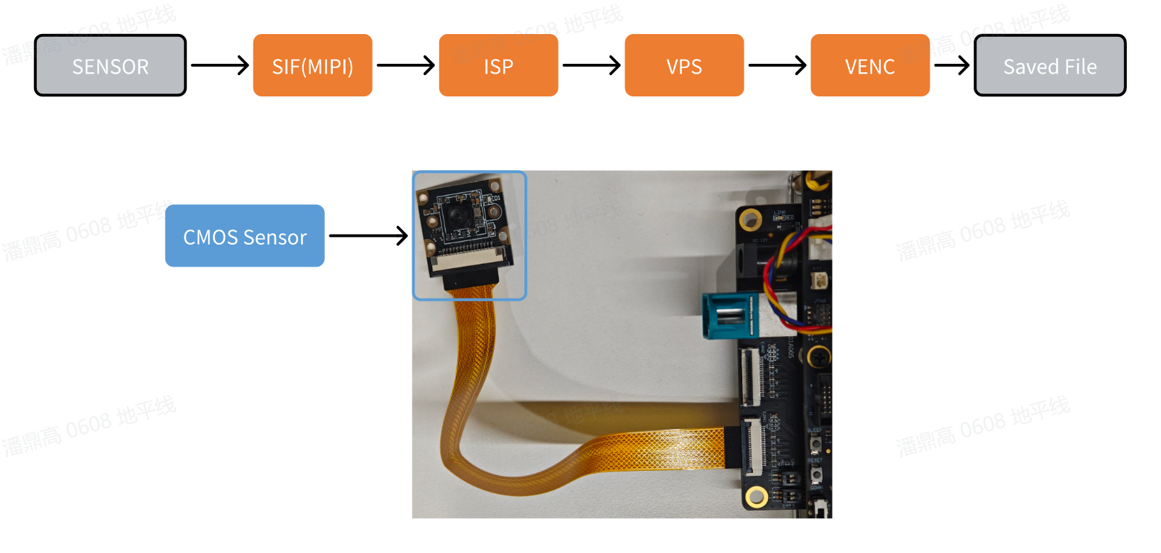
Camera Image Capture and Encoding
The vio2encoder example captures images from a MIPI camera, encodes them, and saves the encoded video locally.
Example flow diagram:
-
Environment Setup:
- With the development board powered off, connect the
MIPIcamera to the board. Currently, this sample only supports MIPI sensors: IMX219, SC230AI. - Power on the development board and log in via the command line.
- With the development board powered off, connect the
-
Execution Method: Run the program using the following commands. The example code is provided in source form and must be compiled using the
makecommand before running. Follow these steps:sunrise@ubuntu:~$ cd /app/cdev_demo/vio2encoder
sunrise@ubuntu:/app/cdev_demo/vio2encoder$ make
sunrise@ubuntu:/app/cdev_demo/vio2encoder$ ./vio2encoder -w 1920 -h 1080 --iwidth 1920 --iheight 1080 -o stream.h264Parameter descriptions:
-w: Encoded video width-h: Encoded video height--iwidth: Sensor output width--iheight: Sensor output height-o: Output path for the encoded video
-
Expected Result: After successful execution, a video file named
stream.h264is generated in the current directory. Sample log output:sunrise@ubuntu:/app/cdev_demo/vio2encoder$ ./vio2encoder -w 1920 -h 1080 --iwidth 1920 --iheight 1080 -o stream.h264
[UCP]: log level = 3
[UCP]: UCP version = 3.7.3
[VP]: log level = 3
[DNN]: log level = 3
[HPL]: log level = 3
[UCPT]: log level = 6
2025/06/16 11:04:37.628 !INFO [CamInitParam][0295]set camera fps: -1,width: 1920,height: 1080
mipi mclk is not configed.
Searching camera sensor on device: /proc/device-tree/soc/vcon@0 i2c bus: 1 mipi rx phy: 0
WARN: Sensor Name: ar0820std-30fps, Expected Chip ID: 0xCB34, Actual Chip ID Read: 0x00
[0] INFO: Found sensor name:imx219-30fps on mipi rx csi 0, i2c addr 0x10, config_file:linear_1920x1080_raw10_30fps_1lane.c
2025/06/16 11:04:37.629 !INFO [CamInitPymParam][0258]Setting PYM channel:0: crop_x:0, crop_y:0, input_width:1920, input_height:1080, dst_w:1920, dst_h:1080
sp_open_camera success!
2025/06/16 11:04:37.770 !INFO [vp_encode_config_param][0408]codec type is h264: frame size:3110912 frame rate: 30
sp_start_encode success!
sp_module_bind(vio -> encoder) success!
^C
recv:2,Stoping...
Video File Decoding and Display
The decoder2display example decodes a video file and outputs it via the HDMI interface, allowing users to preview the video on a monitor.
Example flow diagram:

-
Environment Setup:
- Connect the development board to a monitor using an HDMI cable.
- Power on the development board and log in via the command line.
- Prepare an encoded video file
stream.h264as input.
-
Execution Method: The example code is provided in source form and must be compiled using the
makecommand before running. Follow these steps:sunrise@ubuntu:~$ cd /app/cdev_demo/decode2display
sunrise@ubuntu:/app/cdev_demo/decode2display$ make
sunrise@ubuntu:/app/cdev_demo/decode2display$ ./decoder2display -w 1920 -h 1080 -i /app/res/assets/1080P_test.h264Parameter descriptions:
-h: Height of the video file-w: Width of the video file-i: Path to the video file
-
Expected Result: After the program runs correctly, the video will be output through the development board's
HDMIinterface, and users can preview the video on a monitor. The runtime log is as follows:
sunrise@ubuntu:/app/cdev_demo/decode2display$ ./decoder2display -w 1920 -h 1080 -i /app/res/assets/1080P_test.h264
[UCP]: log level = 3
[UCP]: UCP version = 3.7.3
[VP]: log level = 3
[DNN]: log level = 3
[HPL]: log level = 3
[UCPT]: log level = 6
disp_w=1920, disp_h=1080
sp_start_decode success!
2025/06/16 10:48:49.220 !WARN [sp_start_display][0049]Warning: Using vot_chn values 0-3 is deprecated. Defaulting to HDMI mode.
2025/06/16 10:48:49.221 !WARN [sp_start_display][0050]Please use the new method: pass 10 for DisplayPort (DP) or 11 for HDMI.
2025/06/16 10:48:49.221 !INFO [OpenDisplay][0111]Wayland is available, using Wayland for rendering.

Using default socket path: /run/user/1000/wayland-0
sp_start_display success!
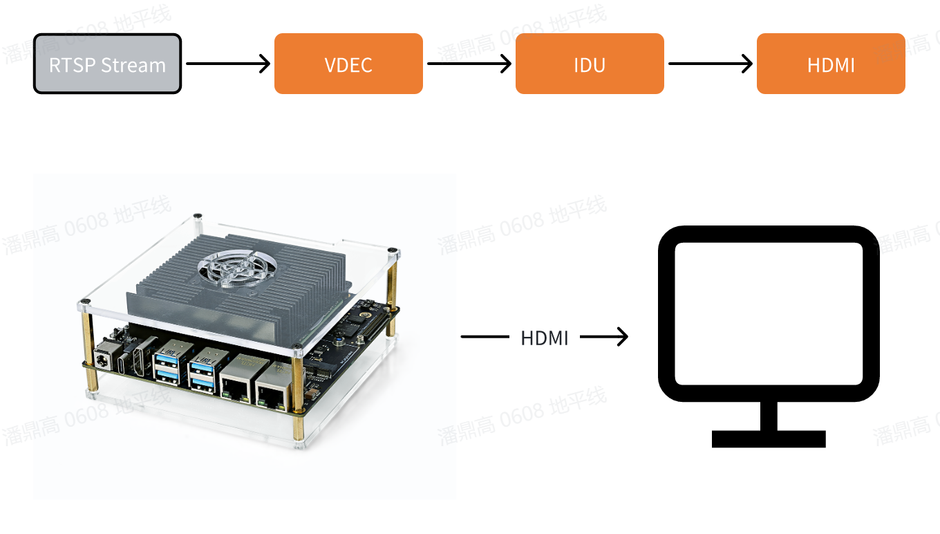
RTSP Stream Pulling and Decoding
This example, rtsp2display, implements the functionality of pulling an rtsp stream, decoding it, and outputting the video via HDMI, allowing users to preview the on a monitor.
Example workflow diagram:
-
Environment Setup:
-
Connect the development board to a monitor using an HDMI cable.
-
Power on the development board and log in via command line.
-
Prepare an
rtspstream as the input source using the pre-installed streaming service. This service converts the1080P_test.h264video file into an RTSP stream with the URLrtsp://127.0.0.1/assets/1080P_test.h264. Users can start the streaming service with the following commands:cd /app/res
sunrise@ubuntu:/app/res# sudo chmod +x live555MediaServer
sunrise@ubuntu:/app/res# sudo ./live555MediaServer &
-
-
How to Run: The example code is provided in source form and must be compiled using the
makecommand before execution. Steps are as follows:sunrise@ubuntu:~$ cd /app/cdev_demo/rtsp2display
sunrise@ubuntu:/app/cdev_demo/rtsp2display$ make # Some warning messages may appear; they can be ignored.
sunrise@ubuntu:/app/cdev_demo/rtsp2display$ ./rtsp2display -i rtsp://127.0.0.1/assets/1080P_test.h264 -t tcpParameter configuration:
-i: Stream URL-t: Transport type, options aretcp/udp
-
Expected Result: After the program runs correctly, the video will be output through the development board's
HDMIinterface, and users can preview the video on a monitor. The runtime log is as follows:sunrise@ubuntu:/app/cdev_demo/rtsp2display$ ./rtsp2display -i rtsp://127.0.0.1/assets/1080P_test.h264 -t tcp
[UCP]: log level = 3
[UCP]: UCP version = 3.7.3
[VP]: log level = 3
[DNN]: log level = 3
[HPL]: log level = 3
[UCPT]: log level = 6
avformat_open_input ok!
avformat_find_stream_info ok!
Input #0, rtsp, from 'rtsp://127.0.0.1/assets/1080P_test.h264':
Metadata:
title : H.264 Video, streamed by the LIVE555 Media Server
comment : 1080P_test.h264
Duration: N/A, start: 0.040000, bitrate: N/A
Stream #0:0: Video: h264 (High), yuv420p(progressive), 1920x1080 [SAR 1:1 DAR 16:9], 25 fps, 25 tbr, 90k tbn, 50 tbc
av_dump_format ok!
rtsp_w:1920,rtsp_h:1080
display_w:1920,dispaly_h:1080
2025/06/16 10:57:21.724 !WARN [sp_start_display][0049]Warning: Using vot_chn values 0-3 is deprecated. Defaulting to HDMI mode.
2025/06/16 10:57:21.724 !WARN [sp_start_display][0050]Please use the new method: pass 10 for DisplayPort (DP) or 11 for HDMI.
2025/06/16 10:57:21.724 !INFO [OpenDisplay][0111]Wayland is available, using Wayland for rendering.
Using default socket path: /run/user/1000/wayland-0
2025/06/16 10:57:21.793 !INFO [CamInitPymParam][0258]Setting PYM channel:0: crop_x:0, crop_y:0, input_width:1920, input_height:1080, dst_w:1920, dst_h:1080
sp_open_vps success!
Could not read frame ---(error 'End of file') -
Notes:
- When using UDP for stream transmission, screen corruption may occur due to packet loss; switching to TCP transmission can resolve this issue.
- If the above command results in a "Connection refused" error, the
127.0.0.1part may need to include the actual port number printed whenlive555MediaServerstarts. For example:# final output of live555MediaServer
...
(We use port 8000 for optional RTSP-over-HTTP tunneling, or for HTTP live streaming (for indexed Transport Stream files only).)
...
# rtsp2display actual command
sunrise@ubuntu:/app/cdev_demo/rtsp2display$ ./rtsp2display -i rtsp://127.0.0.1:8000/assets/1080P_test.h264 -t tcp
VPS Scaling Example
This example implements video scaling based on the Video Processing Subsystem (VPS) module, capable of scaling down a single frame extracted from a video file or scaling a specified image.
-
Environment Setup:
- Power on the development board and log in via command line.
- Prepare an image (NV12) or video file (H264) as input.
-
How to Run: The example code is provided in source form and must be compiled using the
makecommand before execution. Steps are as follows:sunrise@ubuntu:~$ cd /app/cdev_demo/vps
sunrise@ubuntu:/app/cdev_demo/vps$ make
sunrise@ubuntu:/app/cdev_demo/vps$ ./vps -m 1 -i input_1080p.h264 -o output1.yuv --iheight 1080 --iwidth 1920 --oheight 720 --owidth 1280
sunrise@ubuntu:/app/cdev_demo/vps$ ./vps -m 2 -i input_1080p.yuv -o output.yuv --iheight 1080 --iwidth 1920 --oheight 720 --owidth 1280Parameter Configuration:
-i: Path to the input file--iheight: Input height--iwidth: Input width-m: Input mode:1for video stream;2for NV12 image-o: Output path--oheight: Output height--owidth: Output width--skip: (Optional) For video stream input, skip the specified number of initial frames.
-
Expected Result: After the program runs correctly, the processed image file
output.yuvwill be saved in the current directory. The runtime log is as follows:sunrise@ubuntu:/app/cdev_demo/vps$ ./vps -m 1 -i input_1080p.h264 -o output1.yuv --iheight 1080 --iwidth 1920 --oheight 720 --owidth 1280
[UCP]: log level = 3
[UCP]: UCP version = 3.7.3
[VP]: log level = 3
[DNN]: log level = 3
[HPL]: log level = 3
[UCPT]: log level = 6
2025/06/16 10:33:02.709 !INFO [CamInitPymParam][0258]Setting PYM channel:0: crop_x:0, crop_y:0, input_width:1920, input_height:1080, dst_w:1280, dst_h:720
sunrise@ubuntu:/app/cdev_demo/vps$ ./vps -m 2 -i input_1080p.yuv -o output.yuv --iheight 1080 --iwidth 1920 --oheight 720 --owidth 1280
[UCP]: log level = 3
[UCP]: UCP version = 3.7.3
[VP]: log level = 3
[DNN]: log level = 3
[HPL]: log level = 3
[UCPT]: log level = 6
2025/06/16 10:33:29.134 !INFO [CamInitPymParam][0258]Setting PYM channel:0: crop_x:0, crop_y:0, input_width:1920, input_height:1080, dst_w:1280, dst_h:720
... omitted ...