CAN使用指南
基本概述
- 最大可使用CAN controller数量:10。
- CAN最高传输速率:8M。(受限于transceiver的波特率限制,目前实验室只测试验证到5M波特率。)
- 一个controller的Ram内划分的Block个数:
- CAN0~CAN3:4 Block (可变payload);
- CAN4~CAN9:4 Block (可变payload)+ 4 Block(固定payload)。
- 一个controller支持的最大Mailbox个数为128。
- 一个controller支持一路RxFIFO,FIFO深度为:
- CAN0~CAN3:8 * 64 bytes;
- CAN4~CAN9:32 * 64 bytes。
- 不支持 TTController,即不支持TTCAN(一种基于CAN总线的高层协议)。
- CAN支持多包合并传输,并且可以配置合包的数量和超时时间,�默认合包数量为1,超时时间为1000us。
软件架构
S100芯片的CAN控制器位于MCU域,负责CAN数据收发。由于感知等应用位于Acore,因此部分CAN数据需要通过IPC核间通信机制转发到Acore。架构保证传输可靠性,转发机制实现数据正确性检测、丢包检测和传输超时检测等机制。此外,还需要规避MCU侧高频转发小数据块导致CPU占用率过高,造成MCU实时性降低等性能问题。
S100 CAN转发方案的核心流程如下:
- 首先通过MCU侧CAN2IPC模块将CAN通道映射到对应IPC通道,然后通过Acore侧CANHAL模块将IPC通道反映射为虚拟CAN设备通道。最后用户通过CANHAL提供的API接口获取虚拟CAN设备中的数据。其中,CAN2IPC模块为MCU侧服务,CANHAL模块为Acore侧提供给应用程序的动态库。
- CAN采用中断的方式接收数据,当接收到数据之后调用CAN2IPC模块,CAN2IPC模块将MCU侧CAN数据,按照指定传输协议进行打包,然后通过IPC核间通信转发到Acore。Ipc instance 0中的channel0~channel7默认分配给CAN转发使用,Ipc instance 4中的channel7和channel2分配给CAN7和CAN8使用。
- CANHAL模块获取来自MCU侧的IPC数据,按照指定的传输协议解析数据,并支持业务软件通过API获取原始CAN帧。
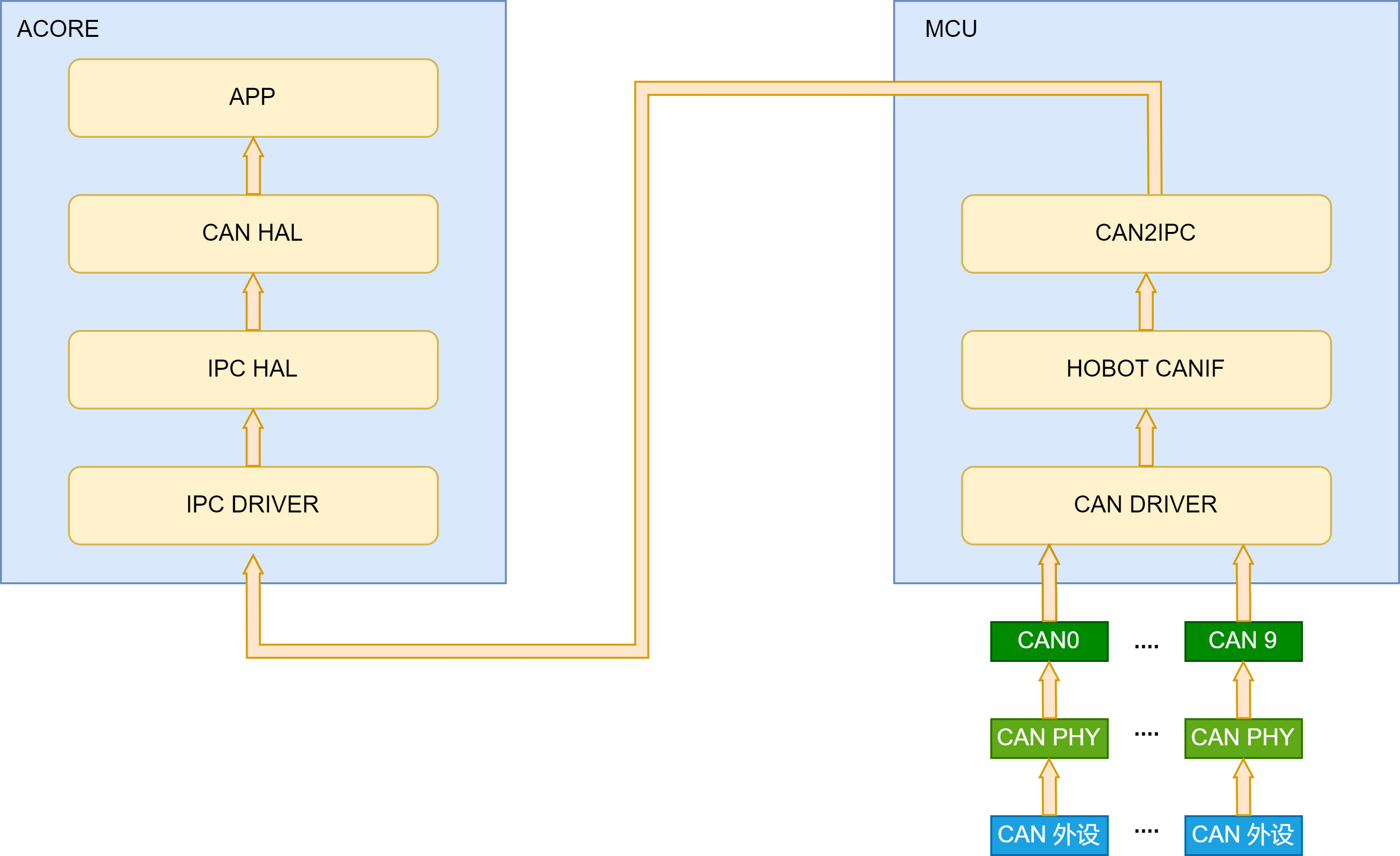
数据流如上图所示:
- 外设数据通过CAN的PHY和控制器器件被MCU域CAN驱动接收后,CAN驱动将数据上报并缓存在hobot CANIF模块。
- 满足合包个数或超时时间,调用CAN2IPC模块,按照可靠传输协议进行打包,然后通过IPC核间通信机制转发给Acore。
- CANHAL模块获取来自MCU侧的IPC数据,按照指定的传输协议解析数据,Acore 应用程序通过CANHAL Lib库提供的API获取CAN帧。
方案特性说明:
- 支持数据透传正确性校验。
- 支持数据透传丢包检测。
- 支持传输超时检测。MCU侧CAN2IPC转发数据时将数据包打上MCU侧的时间戳,Acore CANHAL接收到数据后会读取Acore的时间戳,如果传输超时会报警。注意,需要提前启动时间同步完成MCU RTC时间和Acore 网卡phc0的时间同步。
- 支持多个CAN通道并行传输。MCU侧多个CAN控制器的数据可同时被转发给Acore,Acore应用程序通过CANHAL从不同通道号读出CAN数据。
- 由于CANHAL底层通过ipc核间通信进行传输,而ipc目前不支持多个进程或者线程读写同一个通道,因此CANHAL也不支持该特性。
硬件连接说明
-
CAN物理层的形式主要分为闭环总线及开环总线网络两种,一个适合于高速通讯,一个适合于远距离通讯;S100的sample默认采用闭环总线网络架构。
-
CAN总线的引脚位于S100的MCU扩展板上,引出了5路CAN接口,连接器分别对应了5个绿色的螺丝式的3 PIN连接器。1 PIN(三角标志)为GND,中间PIN为CAN_L,剩下的为CAN_H。
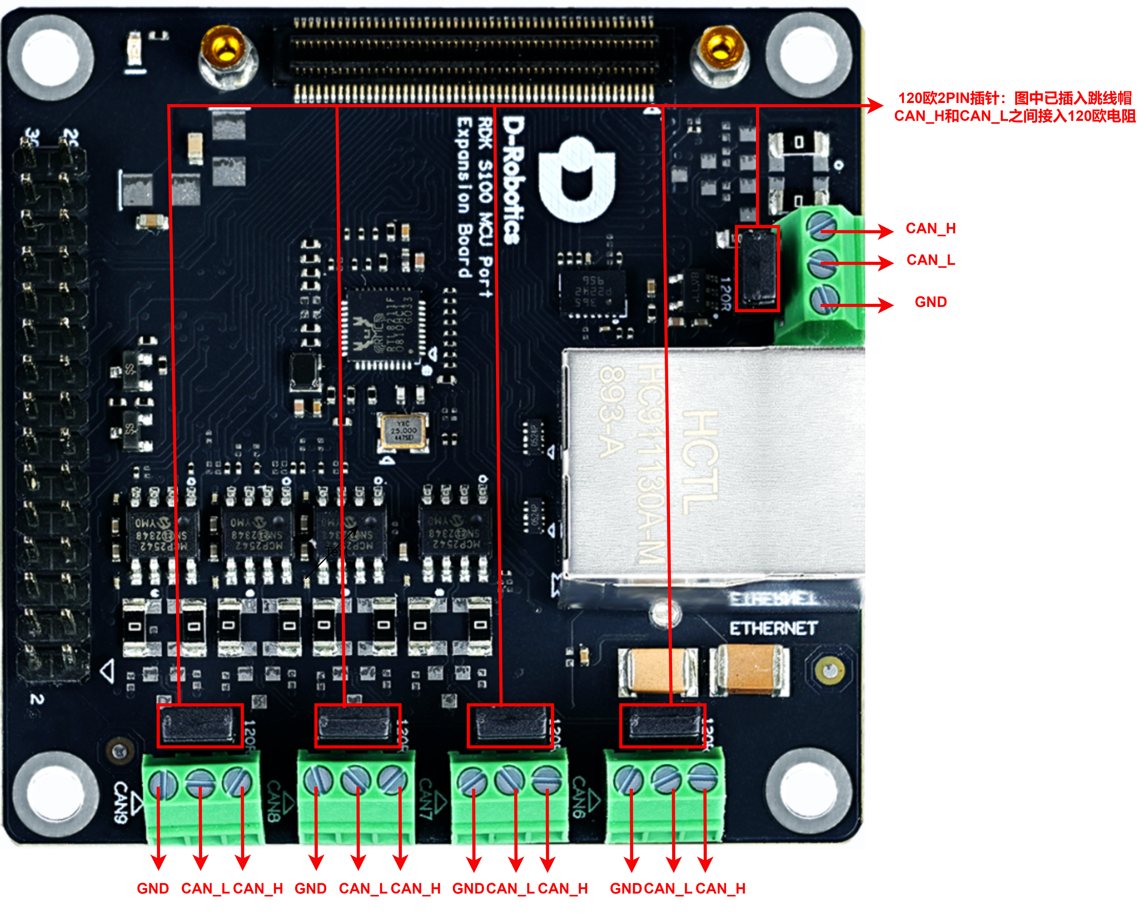
- MCU小板通过2pin跳帽的形式来选择是否在CAN_H和CAN_L之间接入120欧姆�电阻;当插入跳帽时,接入电阻,适用于闭环网络所需的终端匹配阻抗;移除跳帽则断开终端电阻,适用于开环网络或中继节点场景。
CAN闭环网络使用两个120欧姆电阻是CAN总线的标准配置,以下以S100举例,如何正确接入电阻:
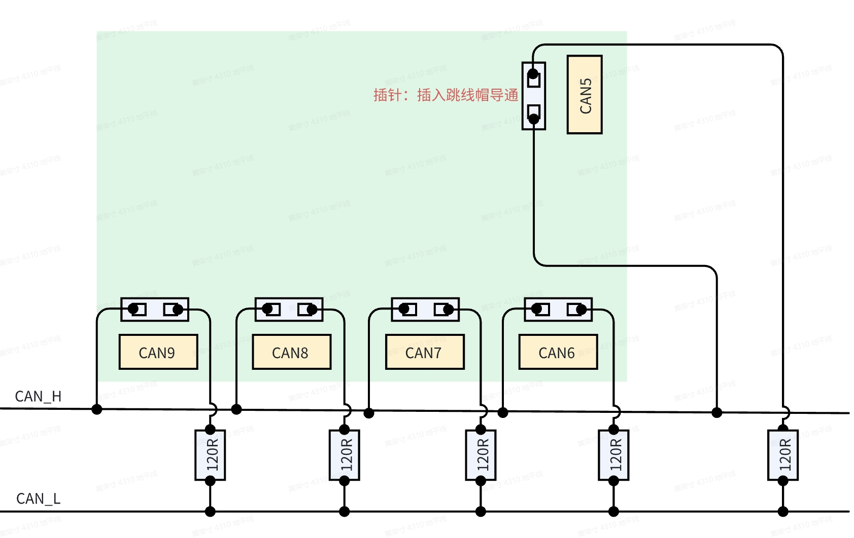
整体而言,开环网络配置不需要接入120欧姆电阻,而闭环网络配置总共需要插入两个120欧姆电阻;
- 在使用开环网络时,确保CAN_H与CAN_L线路正确连接,所用到的CAN不要插入跳线帽(在网络中不接入120欧姆电阻);
- 若将S100的CAN5和CAN6连接组成双节点内部闭环网络,确保CAN_H与CAN_L线路正确连接,还需要在CAN5和CAN6接线端子后面的插针插入跳帽(在网络中插入两个120欧姆电阻);
- 若将S100的CAN5~CAN9连接组成多节点内部闭环网络,确保CAN_H与CAN_L线路正确连接,还需要插入两个跳线帽,任意选择两个,严禁插入超过2个跳线帽,以免出现不可预测的问题;
- 若将S100的CAN5~CAN9中的任意一个控制器和其它CAN设备组成外部闭环网络,确保CAN_H与CAN_L线路正确连接外,还需要在RDK的CAN控制器的接线端子后面的插针插入跳帽,并在网络中其它设备端接入一个120Ω电�阻;
CAN Filter 配置
标准帧的filter最多可配置128个,扩展帧的filter最多可配置64个,可选择的filter类型如下:
- ONE_ID_FILTER:指定ID并可配置MASK来忽略ID中的哪些bit进行过滤,
- RANGE_ID_FILTER:按照ID范围进行过滤,
- TWO_ID_FILTER:指定两个ID进行过滤。
过滤器的识别
过滤器类型通过检查u32HwFilterCode的最高2位来确定:
- 0b00: ONE_ID_FILTER
- 0b01: RANGE_ID_FILTER
- 0b10: TWO_ID_FILTER
/**
 * @struct Can_HwFilterType
 * @brief Can Hardware Filter
 * @NO{S01E03C01}
 */
typedef struct Can_HwFilterType
{
    const uint32 u32HwFilterCode;   /**< @brief Specifies (together with the filter mask) the identifiers range that passes the hardware filter. */
    const uint32 u32HwFilterMask;   /**< @brief Describes a mask for hardware-based filtering of CAN identifiers. */
}Can_HwFilterType;
- 配置举例:
- 这是CAN 7 的过滤器配置,拥有两个过滤器
- 过滤器0的第一个元素的高2位为01,属于范围过滤方式
- 扩展帧和标准帧的过滤相互独立,互不影响
- 标准帧的所有过滤器,如下面的例子过滤器0和过滤1为"或"关系,即如果至少有一个过滤元件满足匹配标准,则CAN消息内容将被传输到增强型RX FIFO存储器
- 同理,扩展帧的所有过滤器,如下面的例子过滤器2和过滤3为"或"关系,即如果至少有一个过滤元件满足匹配标准,则CAN消息内容将被传输到增强型RX FIFO存储器
// Config/McalCdd/gen_s100_sip_B_mcu1/Can/src/Can_PBcfg.c
static const Can_HwFilterType Can_aHwFilter_Object7[4U]=
{
    { /* Standard frame configuration */
        (uint32)0x400007ffU,    // 标准帧配置:接收id为0x0~0x7ff的消息
        (uint32)0x00000000U
    },
    { /* Standard frame configuration */
        (uint32)0x400007ffU,   // 标准帧配置:接收id为0x600~0x7ff的消息
        (uint32)0x00000600U
    },
    { /* Extended frame configuration */
        (uint32)0x5fffffffU,   // 扩展帧配置:接收id为0x0~0x1fffffff的消息
        (uint32)0x00000000U
    },
    { /* Extended frame configuration */
        (uint32)0x5fffffffU,   // 扩展帧配置:接收id为0x600~0x1fffffff的消息
        (uint32)0x00000600U
    }
};
ONE_ID_FILTER(单ID过滤方式)
这是最常见的过滤器类型,使用过滤器代码和掩码进行过滤,伪代码如下:
if ((Received_ID & Filter_Mask) == (Filter_Code & Filter_Mask))
    // 接收该消息
else
    // 丢弃该消
以标准帧过滤器0配置为例,代码如下:
// Config/McalCdd/gen_s100_sip_B_mcu1/Can/src/Can_PBcfg.c
static const Can_HwFilterType Can_aHwFilter_Object7[4U]=
{
    { /* Standard frame configuration */
        (uint32)0x00000400U,  // 只接收id = 0x400&0x7ff = 0x400 消息
        (uint32)0x000007ffU
    },
    {  /* Standard frame configuration */
        (uint32)0x400007ffU,  // 范围过滤方式,支持混用
        (uint32)0x00000600U
    }
    { /* Extended frame configuration */
        (uint32)0x5fffffffU,   // 扩展帧配置:接收id为0x0~0x1fffffff的消息
        (uint32)0x00000000U
    },
    { /* Extended frame configuration */
        (uint32)0x5fffffffU,   // 扩展帧配置:接收id为0x600~0x1fffffff的消息
        (uint32)0x00000600U
    }
};
RANGE_ID_FILTER(范围过滤方式)
在这种模式下,使用范围过滤逻辑:
if (id1 <= Received_ID <= id2)
    // 接收该消息
else
    // 丢弃该消息
这也是S100 MCU默认的过滤方式,也是最常用的过滤方式;举例代码如下:
// Config/McalCdd/gen_s100_sip_B_mcu1/Can/src/Can_PBcfg.c
static const Can_HwFilterType Can_aHwFilter_Object7[4U]=
{
    { /* Standard frame configuration */
        (uint32)0x00000400U,  // 只接收id = 0x400&0x7ff = 0x400 消息
        (uint32)0x000007ffU
    },
    {  /* Standard frame configuration */
        (uint32)0x400007ffU,  // 范围过滤方式,支持混用
        (uint32)0x00000600U
    }
    { /* Extended frame configuration */
        (uint32)0x5fffffffU,   // 扩展帧配置:接收id为0x0~0x1fffffff的消息
        (uint32)0x00000000U
    },
    { /* Extended frame configuration */
        (uint32)0x5fffffffU,   // 扩展帧配置:接收id为0x600~0x1fffffff的消息
        (uint32)0x00000600U
    }
};
TWO_ID_FILTER(双ID过滤方式)
这种类型允许指定两个独立的ID进行匹配:
- id1: 第一个匹配ID
- id2: 第二个匹配ID
if (Received_ID == id1 || Received_ID == id2)
    // 接收该消息
else
    // 丢弃该消息
以标准帧过滤器0配置为例,代码如下:
// Config/McalCdd/gen_s100_sip_B_mcu1/Can/src/Can_PBcfg.c
static const Can_HwFilterType Can_aHwFilter_Object7[4U]=
{
    { /* Standard frame configuration */
        (uint32)0x80000404U,// 只接收id为404的消息
        (uint32)0x00000303U // 只接收id为303的消息
    },
    { /* Standard frame configuration */
        (uint32)0x400007ffU,  // 范围过滤方式,支持混用
        (uint32)0x00000600U
    }
    { /* Extended frame configuration */
        (uint32)0x5fffffffU,   // 扩展帧配置:接收id为0x0~0x1fffffff的消息
        (uint32)0x00000000U
    },
    { /* Extended frame configuration */
        (uint32)0x5fffffffU,   // 扩展帧配置:接收id为0x600~0x1fffffff的消息
        (uint32)0x00000600U
    }
};
- RDK S100软硬件支持收发扩展帧和标准帧,而不需要修改配置
- RDK S100软硬件支持对扩展帧和标准帧分别过滤
- 注意id的长度配置,超出规定长度将发生截断,扩展帧的id长度最高为29位,即最大为0x1FFFFFFF,标准帧的id长度最高为11位,即最大为0x7FF
波特率配置
CAN的标称位时(Nominal bit timing)可以分为四个段:
- 同步段(sync_seg):用于节点间的时钟同步,所有节点在此段内检测信号边沿。其长度固定为1个时间单位(TQ)
- 传播段(prop_seg):补偿信号在物理线路上的传播延迟。其长度可调整,用于确保信号在物理介质上的传输时间
- 相位缓冲段1(phase_seg1):用于调整相位误差,确保采样点的准确性,可以扩展重同步
- 相位缓冲段2(phase_seg2):同样用于调整相位误差,但可以缩短 这些段的总和决定了CAN的总位时间,通过调整这些段的长度,可以配置不同的波特率。 此外还有以下几个重要概念:
- 同步跳转宽度(SJW,synchronization jump width):CAN 总线同步机制中允许调整相位缓冲段的最大时间量,在 硬同步 和 重同步 过程中补偿节点间的时钟偏差,确保采样点对齐。
- 延迟补偿偏移量(Transceiver Delay Compensation Offset):仅 CAN FD 支持,用于解决数据段高速传输时的物理层时序偏移用于补偿 CAN FD 模式下 收发器环路延迟 和 信号传播时间 的固定修正值
- 采样点:CAN控制器在位时间内对总线电平进行采样的精确时刻,用于判定位的逻辑值(显性0或隐性1)
取值范围和公式计算
- 采样点计算:(sync_seg + prop_seg + phase_seg1)/(sync_seg + prop_seg + phase_seg1 + phase_seg2)×100%
- 同步段固定一个tq
- prop_seg + phase_seg1>phase_seg2
- SJW ≤ min(Phase_Seg1, Phase_Seg2)
- 当配置5M及以上波特率时,需配置补偿参数,补偿参数计算公式如下:
- TDC offset = (PropSeg + Seg1 + 1) * Fd Prescaler
配置仲裁段1M数据段5M实例说明
1. 基础参数确认
- CAN时钟频率(CAN_CLK): 40 MHz
- 目标波特率(Bit Rate): 5 Mbps
- 预分频值(Prescaler): 1(不分频)
- 单Bit时间内的TQ总数: TQ = CAN_CLK/(Bit Rate×Prescaler)=40MHz/5Mbps×1=8TQ
- 时间量子:Tq time = 1 / (40M / prescaler) = 1/40M = 25ns
2. 时间量子(TQ)分配
Sync_Seg(固定段): 1 TQ(同步段不可修改)
剩余TQ分配: Prop_Seg+Phase_Seg1+Phase_Seg2=8−1=7TQ
此处取Prop_Seg=1,Phase_Seg1=4,Phase_Seg2=2,则采样点= (Sync_Seg+Prop_Seg+Phase_Seg1)/Total TQ x 100% = (1+4+1)/8 x 100%= 75%
3. 延迟补偿偏移量(Transceiver Delay Compensation Offset)
Offset=(Prop_Seg+Phase_Seg1+1)×Prescaler = (1+4+1)×1=6TQ
SJW(Synchronization Jump Width)设置:
SJW必须满足: SJW≤min(Phase_Seg1,Phase_Seg2)=min(4,2)=2
因此,配置 SJW = 2 TQ。
4. 终配置参数
根据上述的方式同理可以计算到1M情况下的参数,由于部分寄存器获取到的值会自动加一,所以实际写入的值要减一,具体可看下表
- 5M 75%数据段配置
| 参数名 | 值(TQ或时间) | 需写入寄存器的值 |
|---|---|---|
| Sync_Seg | 1 TQ | 无需写入,固定为1 |
| Prop_Seg | 1 TQ | 1 |
| Phase_Seg1 | 4 TQ | 3 |
| Phase_Seg2 | 2 TQ | 1 |
| Prescaler | 1 | 0 |
| SJW | 2 TQ | 1 |
| 延迟补偿偏移量 | 6 TQ | 6 |
- 1M 80%仲裁段配置
| 参数名 | 值(TQ或时间) | 需写入寄存器的值 |
|---|---|---|
| Sync_Seg | 1 TQ | 无需写入,固定为1 |
| Prop_Seg | 7 TQ | 6 |
| Phase_Seg1 | 8 TQ | 7 |
| Phase_Seg2 | 4 TQ | 3 |
| Prescaler | 2 | 1 |
| SJW | 2 TQ | 1 |
5. 8M的配置相对于5M较为特殊,使用60%的采样
| 参数名 | 值(TQ或时间) | 需写入寄存器的值 |
|---|---|---|
| Sync_Seg | 1 TQ | 无需写入,固定为1 |
| Prop_Seg | 1 TQ | 1 |
| Phase_Seg1 | 1 TQ | 0 |
| Phase_Seg2 | 2 TQ | 1 |
| Prescaler | 1 | 0 |
| SJW | 1 TQ | 0 |
| 延迟补偿偏移量 | 3 TQ | 3 |
6. 将结果更新到配置文件中
配置文件路径:
${mcu_sdk}/Config/McalCdd/gen_s100_sip_B_mcu1/Can/src/Can_PBcfg.c
配置文件中存在两个波特率相关的重要结构体,下面以CAN5为例分别说明:
- Can_aControllerConfig:用于配置 CAN 控制器。每个控制器都有一个对应的配置项
static const Can_ControllerConfigType Can_aControllerConfig[CAN_CONTROLLER_CONFIG_COUNT]=
{
    ...
 {
        /* Controller ID configured */
        (uint8)5U,
        /* Hw controller Offset */
        (uint8)5U,
        /* Base Address */
        FLEXCAN_5_BASE,
        /* Activation or not */
        (boolean)TRUE,
        /* Bus Off uses polling or not */
        (boolean)TRUE,
        /* Global mask of Legacy FIFO (not used) */
        (uint32)0xFFFFFFFFU,
        /* Acceptance Mode of Legacy FIFO (not used)*/
        CAN_LEGACY_FIFO_FORMAT_A,
        /* Legacy FIFO Warning Notification */
        NULL_PTR,
        /* Legacy FIFO Overflow Notification */
        NULL_PTR,
        /* Enhanced FIFO Overflow Notification */
        NULL_PTR,
        /* Error interrupt enable or not */
        (boolean)TRUE,
        /* Can Error Notification */
        Can_ErrorNotif,
        /* CanFd Error Notification */
        CanFd_ErrorNotif,
        /* Default Baudrate ID, 4--1M+5M 5--1M+8M */
        (uint16)4U,
         /* Baudrate config Count*/
        (uint16)6U,
        /* Pointer to baudrate config Structure */
        Can_aBaudrateConfig_Ctrl5,
        /* Pointer to LLD structure to IP config */
        &Flexcan_aCtrlConfigPB[5U],
        /* HwObject count */
        (uint8)9U,
        /* Point to group of HwObject that referenced to the current Controller */
        Can_apHwObject_Ctrl5
    },
    ...
}
- Can_aBaudrateConfig_Ctrl5:用于定义特定控制器的波特率配置,这是一个大数组,上述步骤中生成的参数均写到这个数组中
static const Can_BaudrateConfigType Can_aBaudrateConfig_Ctrl5[6U]=
{
{
/*Enhance CBT support */
(boolean)TRUE,
/* Tx Bit Rate Switch or not */
(boolean)TRUE,
/* CanFd support */
(boolean)TRUE,
/* Nominal bit rate */ //仲裁段配置
{
(uint8)6U, // 传播段(prop_seg)
(uint8)7U, // 相位缓冲段1(phase_seg1)
(uint8)3U, // 相位缓冲段2(phase_seg2)
(uint16)3U, // 预分频值(Prescaler)
(uint8)1U //同步跳转宽度(SJW)
},
/* Data bit rate */ //数据段配置
{
(uint8)3U,
(uint8)3U,
(uint8)1U,
(uint16)3U,
(uint8)1U
},
/* Tx Arbitration Start delay */
(uint8)12U, // 延迟补偿偏移量(Transceiver Delay Compensation Offset)
/* Tranceiver Delay Disable */
(boolean)FALSE,
(uint8)0U
},
...
RDK S100默认配置了6组参数,用户可以通过修改Can_aControllerConfig中的u16DefaultBaudrateID成员值来选择波特率,下表为索引对应的波特率参数:
| u16DefaultBaudrateID | 仲裁段频率 | 数据段频率 |
|---|---|---|
| 0 | 500K | 1M |
| 1 | 500K | 2M |
| 2 | 1M | 2M |
| 3 | 1M | 5M(短距离:小于50m) |
| 4 | 1M | 5M(长距离:大于50m) |
| 5 | 1M | 8M |
多包合并配置
CAN驱动支持接收多包合并数据传输功能,当CAN驱动接收到一定阈值的数据包时,会将它们合并,通过IPC从MCU传输到Acore。目的是为了减少IPC传输频率,提高传输效率。在此基础上提供了合包数量和超时时间两个可配参数。
- 合包数量:用于设置CAN驱动接收到多少包之后,进行一次IPC传输, 默认为1。
- 超时时间:用于当一定时间内还没有收到所设阈值的数据包时,进行一次强制传输,默认为1000us。
配置方式
进入MCU串口配置方式如下:
D-Robotics:/$ Can
Can_Set_Merge_Time    CMD   --------  Set the CAN packet merge timeout in ...
Can_Set_Merge_Num     CMD   --------  Set the number of CAN packages to me...

D-Robotics:/$ Can_Set_Merge_Num 8   // 设置合包数量为8

D-Robotics:/$ Can_Set_Merge_Time 100  // 设置超时时间为100us
acore侧也支持多包合并传输功能,下面只简单介绍相关数据结构,具体可以使用应用sample中提供的测试用例进行修改验证。
#define CAN_FRAME_NUM (1)   // Acore侧表示合并传输数据包的数量
struct pack_info pack = { 0 };
pack.data_num = CAN_FRAME_NUM;
应用sample
使用指南
执行 sample 之前需要先开启MCU1,MCU1开启的流程参考开启 MCU。
Acore canhal使用可参考sample源码目录:source/hobot-io-samples/debian/app/Can,可以在S100的/app/Can目录下直接make编译使用。
以多路透传为例,目录结构如下:
$ tree /app/Can/can_multi_ch
.
├── Makefile // 主编译脚本
├── config  // 配置文件目录
│   ├── channels.json // 通道映射配置文件
│   ├── ipcf_channel.json // IPCF通道映射配置文件
│   └── nodes.json // Can虚拟设备映射配置文件
├── main.cpp // 主程序
├── readme.md // 说明文件
├── can_multich_log.h // 日志头文件
└── run.sh // 运行脚本
json文件配置主要包括3个json配置文件:node.json、ipcf_channel.json、channels.json。目前为了支持多进程,各个进程都会去当前路径下的config目录下寻找这3个配置文件。
node.json负责创建虚拟CAN设备节点给CANHAL API访问。关键配置选项包括:
- channel_id字段指定该虚拟CAN设备从ipc配置文件ipcf_channel.json中哪一个节点获取数据。
- target字段表示该虚拟CAN设备节点的名称,CANHAL API通过该名称访问指定的节点。
- enable字段表示该节点是否使能。
{
  "nodes" : [
    {
      "id" : 0,
      "enable" : true,
      "mode_comment" : "value_table: R, W, RW",
      "mode" : "RW",
      "target" : "can6_ins0ch6",
      "clk_source" : "/dev/hrtc0",
      "io_channel" : {
        "device_type_comment" : "value_table: can, eth, ipcf, spi",
        "device_type" : "ipcf",
        "channel_id" : 0
      },
      "raw_protocol" : "built_1.0"
    },
    .....
    {
      "id" : 4,
      "enable" : true,
      "mode_comment" : "value_table: R, W, RW",
      "mode" : "RW",
      "target" : "can5_ins0ch4",
      "clk_source" : "/dev/hrtc0",
      "io_channel" : {
        "device_type_comment" : "value_table: can, eth, ipcf, spi",
        "device_type" : "ipcf",
        "channel_id" : 4
      },
      "raw_protocol" : "built_1.0"
    }
  ]
}
ipcf_channel.json将node.json中用到的ipc节点映射到具体的instance和channel。
{
  "enable" : true,
  "libipcf_path" : "/usr/hobot/lib/libhbipcfhal.so.1",
  "channels" : [
    {
      "id" : 0,
      "channel" : {
        "name" : "can6_ins0ch6",
        "instance": 0,
        "channel": 6,
        "fifo_size": 64000,
        "fifo_type": 0,
        "pkg_size_max": 4096,
        "dev_path":"/dev/ipcdrv",
        "dev_name":"ipcdrv",
        "recv_timeout" : 4000
      }
    },
    ......
    {
      "id" : 4,
      "channel" : {
        "name" : "can5_ins0ch4",
        "instance": 0,
        "channel": 4,
        "fifo_size": 64000,
        "fifo_type": 0,
        "pkg_size_max": 4096,
        "dev_path":"/dev/ipcdrv",
        "dev_name":"ipcdrv",
        "recv_timeout" : 4000
      }
    }
  ]
}
channels.json指定ipc配置文件,用户一般不需要更改。
{
  "io_channels" : {
   "ipcf" : "./config/ipcf_channel.json"
 }
}
Acore无法直接操作CAN外设,需要通过借助Ipc模块来中转数据,与外设通道的映射关系可以查阅 MCU IPC使用指南 中的IPC 使用情况章节。
Acore应用程序通过CANHAL获取MCU侧CAN帧的流程伪代码如下:
void send_frame_data(void *arg)
{
... do
{
ret = canSendMsgFrame(test_params->target, &frame[0], &pack);
if (ret > 0) { /* 发送成功 */
send_count++;
PRINT_DEBUG("Send length %d\n", ret);
break;
} else if (ret == -CAN_TRY_AGAIN && /* 由于IPC或者其他资源不足,重试 */
retry++ < MAX_RETRY) {
usleep(2);
continue;
} else { /* 发送失败 */
PRINT_ERR("Send failed after retries, exiting...\n");
break;
}
}
while (1)
;
}
void *recv_frame_data(void *arg)
{
while (!exit_flag) {
ret = canRecvMsgFrame(target, frame, &pack); // non blocking
if (ret < 0) {
if (ret == -CAN_TRY_AGAIN) { /* 由于IPC或者其他资源不足,重试 */
PRINT_DEBUG("canRecvMsgFrame try again\n");
continue;
} else {
PRINT_ERR("canRecvMsgFrame failed ret: %d\n", ret);
gettimeofday(¤t_time, NULL);
double elapsed =
difftime(current_time.tv_sec, last_recv_time.tv_sec);
if (elapsed > RECV_TIMEOUT) { /* 超时退出 */
PRINT_INFO(
"No data received for %d seconds. Exiting thread.\n",
RECV_TIMEOUT);
goto can_recv_exit;
}
continue;
}
}
}
}
int main(int argc, char *argv[])
{
ret = canInit();
pthread_create(&send_thread, NULL, send_frame_data, &tx_params);
pthread_create(&rx_threads[i], NULL, recv_frame_data, &rx_params[i])
pthread_join(send_thread, NULL);
pthread_join(rx_threads[i], NULL);
canDeInit();
}
- 首先执行canInit()完成初��始化,然后创建发送线程和接收线程
- 发送线程调用canSendMsgFrame()发送数据包,接收线程调用canRecvMsgFrame()接收数据包,其中target参数为json文件中配置好的通道。
- pack信息包含这一包数据的信息,包括can帧数量、mcu侧的时间戳以及acore侧的monotic时间戳等信息。
- canhal会从这一包ipc数据中解析出can帧,用户通过frame指针读取出所有can帧。
- 最后执行canDeInit()释放资源。
can的接收和发送函数依赖IPC的资源,当传输速率过快时会出现资源耗尽的情况,此时可以进行降速和重传。
ACORE侧实例说明
简单的can收发sample
目录介绍
// /app/Can/can_send
.
├── Makefile // 主编译脚本
├── canhal_send.c // 发送一帧标准帧数据
└── config // 配置文件目录
    ├── channels.json  // 通道映射配置文件
    ├── ipcf_channel.json  // 通道映射配置文件
    └── nodes.json // 通道映射配置文件

// /app/Can/can_get
.
├── Makefile // 主编译脚本
├── canhal_get.c // while 1循环,接收数据
└── config // 配置文件目录
    ├── channels.json   // 通道映射配置文件
    ├── ipcf_channel.json  // 通道映射配置文件
    └── nodes.json  // 通道映射配置文件
使用前提
这里仅给出一个简单的sample,实际应用中需要根据实际需求进行修改。
使用前提:
- MCU1正常运行
- 硬件连接:使用CAN闭环总线网络,CAN5连接CAN6,CAN_H和CAN_L之间接入120欧姆电阻(CAN5和CAN6接线柱后面的2 PIN引脚使用跳线帽或杜邦线短接)。
- 由于can_send和can_get都使用的instance channel4(默认映射来自CAN5的数据),由于Ipc单个channel只能被一个线程使用,因此修改can_send中的ipcf_channel.json,改为使用instance channel6,改动如下
{
  "enable" : true,
  "libipcf_path" : "/usr/hobot/lib/libhbipcfhal.so.1",
  "channels" : [
    {
      "id" : 0,
      "channel" : {
        "name" : "bypass",
        "instance": 0,
        "channel": 6, // 这里由4改成了6
        "fifo_size": 64000,
        "fifo_type": 0,
        "pkg_size_max": 4096,
        "dev_path":"/dev/ipcdrv",
        "dev_name":"ipcdrv",
        "recv_timeout" : 4000
      }
    }
  ]
}
使用方式
- 分别编译can_send和can_get两个sample
- 进入can_get目录执行以下命令
./canhal_get bypass &
- 进入can_send目录执行以下命令
root@ubuntu:/app/Can/can_send# ./canhal_send bypass 6
[CANHAL][INFO][ipcf_dev.cpp:32][2025-2-20 21:43:47.522]:the path of ipcf plugin is /usr/hobot/lib/libhbipcfhal.so.1.
group name is bypass
[CANHAL][INFO][comps_mgr.cpp:158][2025-2-20 21:43:47.523]:channel constructor Register dev: ipcf success.
[CANHAL][INFO][node.cpp:17][2025-2-20 21:43:47.523]:channel id is 0
[INFO][hb_ipcf_hal.cpp:282] [channel] bypass [ins] 0 [id] 6 init success.
[INFO][hb_ipcf_hal.cpp:333] [channel] bypass [ins] 0 [id] 6 config success.
[CANHAL][INFO][node.cpp:39][2025-2-20 21:43:47.523]:io_channel init successful
[CANHAL][INFO][node.cpp:44][2025-2-20 21:43:47.523]:protocol is built_1.0
Send end, send package total: 1 frame total: 1
[CANHAL][INFO][can_hal_impl.cpp:120][2025-2-20 21:43:47.524]:Deinit node: bypass
[INFO][hb_ipcf_hal.cpp:553] [channel] bypass [ins] 0 [id] 6 deinit success.
[CANHAL][INFO][can_hal_impl.cpp:128][2025-2-20 21:43:47.524]:Deinit node: bypass
[CANHAL][INFO][channel_ctor.cpp:47][2025-2-20 21:43:47.524]:Deinit device: ipcf
*********************************************
[bypass] [pack]length: 1 soc_ts: 1186831 mcu_ts: 1191955
[canhal_get] [bypass] [canframe] canid is 0x00000131 timestamp is 0x123013 data is:
 0x0  0xaa  0xaa  0xaa  0xaa  0xaa  0xaa  0xfc
- 出现如下打印则测试成功:
[canhal_get] [bypass] [canframe] canid is 0x00000131 timestamp is 0x10b221 data is:
 0x0  0xaa  0xaa  0xaa  0xaa  0xaa  0xaa  0xfc
多通道传输
目录介绍
// /app/Can/can_multi_ch
.
├── Makefile // 主编译脚本
├── config  // 配置文件目录
│   ├── channels.json // 通道映射配置文件
│   ├── ipcf_channel.json // IPCF通道映射配置文件
│   └── nodes.json // Can虚拟设备映射配置文件
├── main.cpp // 主程序
├── readme.md // 说明文件
├── can_multich_log.h // 日志头文件
└── run.sh // 运行脚本
本程序实现CAN总线多通道数据发送与接收:
- 硬件连接:使用CAN闭环总线网络,Can6连接Can7, Can8连接Can9,Can5单独通道不接,CAN_H和CAN_L之间接入120欧姆电阻(把所用到的CAN总线的接线柱后面的2 PIN引脚使用跳线帽或杜邦线短接)。
- 发送线程:为每个通道创建独立线程发送数据,当使用CANFD时,数据包含计数器和时间戳,当使用经典CAN时,数据为全0x55。
- 接收线程:为每个通道创建独立线程接收数据并验证数据正确性。
发送策略:
- 相隔固定时间通过Can发送数据,可通过修改延时调整发送频率,频率过高可能会出现丢包。
- 目标通道:控制CAN5~CAN9广播数据
接收策略:
- 被动接收数据,验证接收数据的计数器和计算传输时延
- 超过100秒未收到数据则退出程序(代码中定义的超时时间)
依赖
pthread: 线程库hobot_can_hal: CAN接口库hb_ipcf_hal: IPCF接口库alog: Android日志库
通道映射关系
| 通道 | 对应线程名称 | 设备名 |
|---|---|---|
| CAN5 | CAN5RX | "can5_ins0ch4" |
| CAN6 | CAN6RX | "can6_ins0ch6" |
| CAN7 | CAN7RX | "can7_ins4ch7" |
| CAN8 | CAN8RX | "can8_ins4ch2" |
| CAN9 | CAN9RX | "can9_ins0ch3" |
DEBUG开关
// can_multich_log.h
#define VERBOSE 0 //修改为1时打印调试信息
也可以使用logcat查看更多日志
发送端
发送策略:
- 相隔固定时间通过Can发送数据,可通过修改延时调整发送频率,频率过高可能会出现丢包。
- 数据内容:通过CANFD发送扩展帧(64bytes)的数据。
- 目标通道:CAN5~CAN9每个通道都发送数据
接收端
接收策略:
- 被动接收数据,验证接收数据的计数器和计算传输时延
- 超过100秒未收到数据则退出程序(代码中定义的超时时间)
注意事项
- 程序退出时会自动释放CAN设备资源
- 按Ctrl+C可中断程序运行
- 支持命令行参数配置发送帧数、CAN帧类型和数据长度
编译命令
make # 编译
make clean # 清除编译文件
命令行参数
程序支持以下命令行参数来自定义运行参数:
-n <can_tran_num>                 指定要发送的帧数 (默认: 1)
-t <can_type>                     指定CAN帧类型 (0: 标准帧, 1: 扩展帧, 2: FD标准帧, 3: FD扩展帧) (默认: 2)
-l <can_length>                   指定CAN帧长度 (8: 8字节, 64: 64字节) (默认: 64)
-h, --help                        显示帮助信息
运行命令
export CAN_HAL_DEBUG_LEVEL=6 //  设置CAN接口库调试等级,不打印任何日志;打印较多的情况下会影响发送频率
./can_multi_ch
或者使用参数运行:
./can_multi_ch -t 2 -l 64 -n 5
日志分析
以运行 ./can_multi_ch -t 2 -l 64 -n 5 为例:
-
当前默认参数配置:
[param_config_display 389] [INFO]: Current parameter configuration:
[param_config_display 390] [INFO]:   CAN Transmit Number: 1
[param_config_display 391] [INFO]:   CAN Type: CAN_FD_STANDARD
[param_config_display 392] [INFO]: CAN Length: 64 -
使用的硬件配置,CAN控制器,IPC的实例和通道
group name is can6_ins0ch6
group name is can7_ins4ch7
group name is can8_ins4ch2
group name is can9_ins0ch3
group name is can5_ins0ch4 -
使用的硬件配置,CAN控制器,IPC的实例和通道
group name is can6_ins0ch6
group name is can7_ins4ch7
group name is can8_ins4ch2
group name is can9_ins0ch3
group name is can5_ins0ch4 -
通道初始化信息
[INFO][hb_ipcf_hal.cpp:282] [channel] can6_ins0ch6 [ins] 0 [id] 6 init success.
[INFO][hb_ipcf_hal.cpp:333] [channel] can6_ins0ch6 [ins] 0 [id] 6 config success.
[INFO][hb_ipcf_hal.cpp:282] [channel] can7_ins4ch7 [ins] 0 [id] 7 init success.
[INFO][hb_ipcf_hal.cpp:333] [channel] can7_ins4ch7 [ins] 0 [id] 7 config success.
[INFO][hb_ipcf_hal.cpp:282] [channel] can8_ins4ch2 [ins] 0 [id] 2 init success.
[INFO][hb_ipcf_hal.cpp:333] [channel] can8_ins4ch2 [ins] 0 [id] 2 config success.
[INFO][hb_ipcf_hal.cpp:282] [channel] can9_ins0ch3 [ins] 0 [id] 3 init success.
[INFO][hb_ipcf_hal.cpp:333] [channel] can9_ins0ch3 [ins] 0 [id] 3 config success.
[INFO][hb_ipcf_hal.cpp:282] [channel] can5_ins0ch4 [ins] 0 [id] 4 init success.
[INFO][hb_ipcf_hal.cpp:333] [channel] can5_ins0ch4 [ins] 0 [id] 4 config success. -
发送线程发送的数据打印,可以看到发到成功将多少帧数据转发到MCU,速率如何
[send_frame_data 266] [INFO]: Target can5_ins0ch4 Time: 0.005230s
[send_frame_data 268] [INFO]: Send success count: 5 Total:5
[send_frame_data 271] [INFO]: 61185.468750 byte/s -> 59.751434kb/s
[send_frame_data 274] [INFO]: Sending FPS: 956.02 frames/s
[send_frame_data 276] [INFO]: Send end, send package total: 5 frame total: 5
[send_frame_data 278] [INFO]: Send thread exiting...
[send_frame_data 266] [INFO]: Target can6_ins0ch6 Time: 0.005074s
[send_frame_data 268] [INFO]: Send success count: 5 Total:5
[send_frame_data 271] [INFO]: 63066.613281 byte/s -> 61.588490kb/s
[send_frame_data 274] [INFO]: Sending FPS: 985.42 frames/s
[send_frame_data 276] [INFO]: Send end, send package total: 5 frame total: 5
[send_frame_data 278] [INFO]: Send thread exiting...
[send_frame_data 266] [INFO]: Target can7_ins4ch7 Time: 0.004979s
..... -
接收超时,起接收线程后会等待接收数据,长时间没有接收错误会报-303错误,可根据实际情况判断是否存在异常,当超过100s时候,会退出线程
[recv_frame_data 307] [ERR]: canRecvMsgFrame failed ret: -303
[recv_frame_data 307] [ERR]: canRecvMsgFrame failed ret: -303
[recv_frame_data 307] [ERR]: canRecvMsgFrame failed ret: -303
[recv_frame_data 307] [ERR]: canRecvMsgFrame failed ret: -303
[recv_frame_data 307] [ERR]: canRecvMsgFrame failed ret: -303
[recv_frame_data 307] [ERR]: canRecvMsgFrame failed ret: -303
[recv_frame_data 307] [ERR]: canRecvMsgFrame failed ret: -303
[recv_frame_data 307] [ERR]: canRecvMsgFrame failed ret: -303
[recv_frame_data 307] [ERR]: canRecvMsgFrame failed ret: -303
[recv_frame_data 307] [ERR]: canRecvMsgFrame failed ret: -303
[recv_frame_data 307] [ERR]: canRecvMsgFrame failed ret: -303
[recv_frame_data 314] [INFO]: No data received for 100 seconds. Exiting thread. -
按ctrl+c退出后可以看到各个接收线程中收到包的数量,接收的最大延迟(仅CAN FD支持),由于CAN5没有接设备,所以接收到的包数量为0
Target :can7_ins4ch7 recv frame num: 5 Total recv frame num: 5 Maximum transmission time:32209 us
Target :can6_ins0ch6 recv frame num: 5 Total recv frame num: 5 Maximum transmission time:41182 us
Target :can8_ins4ch2 recv frame num: 5 Total recv frame num: 5 Maximum transmission time:22676 us
Target :can9_ins0ch3 recv frame num: 5 Total recv frame num: 5 Maximum transmission time:11395 us
Target :can5_ins0ch4 recv frame num: 0 Total recv frame num: 5 Maximum transmission time:0 us -
资源释放
[INFO][hb_ipcf_hal.cpp:553] [channel] can5_ins0ch4 [ins] 0 [id] 4 deinit success.
[INFO][hb_ipcf_hal.cpp:553] [channel] can8_ins4ch2 [ins] 0 [id] 2 deinit success.
[INFO][hb_ipcf_hal.cpp:553] [channel] can9_ins0ch3 [ins] 0 [id] 3 deinit success.
[INFO][hb_ipcf_hal.cpp:553] [channel] can7_ins4ch7 [ins] 0 [id] 7 deinit success.
[INFO][hb_ipcf_hal.cpp:553] [channel] can6_ins0ch6 [ins] 0 [id] 6 deinit success.
多can组网传输
持续更新中
应用层修改can波特率等配置
持续更新中
库文件打印开关
CAN_HAL_DEBUG_LEVEL 是一个环境变量,用于控制库文件libhbcanhal.so日志输出的级别。它的不同值代表不同的日志级别,这些级别决定了哪些日志信息会被记录下来
0 (log_trace): 跟踪级别。
1 (log_debug): 调试级别。
2 (log_info): 信息级别。
3 (log_warn): 警告级别。
4 (log_err): 错误级别。
5 (log_critical): 致命级别。
6 (log_never): 不打印任何日志。
通过设置 CAN_HAL_DEBUG_LEVEL 的值,可以控制日志输出的详细程度。例如,如果设置为 2,那么只有 log_info、log_warn、log_err 和 log_critical 级别的日志会被打印
MCU侧DEBUG应用说明
- 进入MCU1的控制台
- 输入命令:can_tran_debug
can_tran_debug
-
在
/sys/class/remoteproc/remoteproc_mcu1路径下使用cat log命令查看结果
应用程序接口
void Can_Init(const Can_ConfigType* Config)
Description:This function initializes the module.

Sync/Async: Synchronous
Parameters(in)
    Config: Pointer to driver configuration.
Parameters(inout)
    None
Parameters(out)
    None
Return value:None
void Can_GetVersionInfo(Std_VersionInfoType* versioninfo)
Description:Returns the version information of this module.

Sync/Async: Synchronous
Parameters(in)
    None
Parameters(inout)
    None
Parameters(out)
    versioninfo: Pointer to where to store the version information of this module.
Return value:None
void Can_DeInit(void)
Description:This function de-initializes the module.

Sync/Async: Synchronous
Parameters(in)
    None
Parameters(inout)
    None
Parameters(out)
    None
Return value:None
Std_ReturnType Can_SetControllerMode(uint8 Controller, Can_ControllerStateType Transition)
Description:This function performs software triggered state transitions of the CAN controller State machine.

Sync/Async: Synchronous
Parameters(in)
    Controller: CAN controller for which the status shall be changed.
    Transition: Transition value to request new CAN controller state.
Parameters(inout)
    None
Parameters(out)
    None
Return value:Std_ReturnType
	E_OK: request accepted.
    E_NOT_OK: request not accepted, a development error occurred.
void Can_DisableControllerInterrupts(uint8 Controller)
Description:This function disables all interrupts for this CAN controller.

Sync/Async: Synchronous
Parameters(in)
    Controller: CAN controller for which interrupts shall be disabled.
Parameters(inout)
    None
Parameters(out)
    None
Return value:None
void Can_EnableControllerInterrupts(uint8 Controller)
Description:This function enables all allowed interrupts.

Sync/Async: Synchronous
Parameters(in)
    Controller: CAN controller for which interrupts shall be re-enabled.
Parameters(inout)
    None
Parameters(out)
    None
Return value:None
Std_ReturnType Can_GetControllerErrorState(uint8 ControllerId, Can_ErrorStateType* ErrorStatePtr)
Description:This service obtains the error state of the CAN controller.

Sync/Async: Synchronous
Parameters(in)
    ControllerId: Abstracted CanIf ControllerId which is assigned to a CAN controller, which is requested for ErrorState.
Parameters(inout)
    None
Parameters(out)
    ErrorStatePtr:Pointer to a memory location, where the error state of the CAN controller will be stored.
Return value:Std_ReturnType
	E_OK: Error state request has been accepted.
    E_NOT_OK: Error state request has not been accepted.
Std_ReturnType Can_GetControllerMode(uint8 Controller, Can_ControllerStateType* ControllerModePtr)
Description:This service reports about the current status of the requested CAN controller.

Sync/Async: Synchronous
Parameters(in)
    Controller: CAN controller for which the status shall be requested.
Parameters(inout)
    None
Parameters(out)
    ControllerModePtr: Pointer to a memory location, where the current mode of the CAN controller will be stored.
Return value:Std_ReturnType
    E_OK: Controller mode request has been accepted.
    E_NOT_OK: Controller mode request has not been accepted.
Std_ReturnType Can_GetControllerRxErrorCounter(uint8 ControllerId, uint8* RxErrorCounterPtr)
Description:Returns the Rx error counter for a CAN controller.
             This value might not be available for all CAN controllers, in which case E_NOT_OK would be
             returned.Please note that the value of the counter might not be correct at the moment the
             API returns it, because the Rx counter is handled as ynchronously in hardware.Applications
             should not trust this value for any assumption about the current bus state.

Sync/Async: Synchronous
Parameters(in)
    ControllerId: CAN controller, whose current Rx error counter shall be acquired.
Parameters(inout)
    None
Parameters(out)
    RxErrorCounterPtr: Pointer to a memory location, where the current Rx error counter of the
                       CAN controller will be stored.
Return value:Std_ReturnType
    E_OK: Rx error counter available.
    E_NOT_OK: Wrong ControllerId, or Rx error counter not available.
Std_ReturnType Can_GetControllerTxErrorCounter(uint8 ControllerId, uint8* TxErrorCounterPtr)
Description:Returns the Tx error counter for a CAN controller. This value might not be available
             for all CAN controllers, in which case E_NOT_OK would be returned.Please note that the
             value of the counter might not be correct at the moment the API returns it, because the
             Tx counter is handled as ynchronously in hardware.Applications should not trust this
             value for any assumption about the current bus state.

Sync/Async: Synchronous
Parameters(in)
    ControllerId: CAN controller, whose current Rx error counter shall be acquired.
Parameters(inout)
    None
Parameters(out)
    TxErrorCounterPtr:Pointer to a memory location, where the current Tx error counter
                      of the CAN controller will be stored.
Return value:Std_ReturnType
    E_OK: Rx error counter available.
    E_NOT_OK: Wrong ControllerId, or Rx error counter not available.
Std_ReturnTypeCan_Write(Can_HwHandleType Hth, const Can_PduType* PduInfo)
Description:This function is called by CanIf to pass a CAN message to CanDrv for tran smission.

Sync/Async: Synchronous
Parameters(in)
    Hth:information which HW-transmit handle shall be used for transmit.Implicitly this is
        also the information about the controller to use because the Hth numbers are unique
        inside one hardware unit.
Parameters(inout)
    None
Parameters(out)
    None
Return value:Std_ReturnType
    E_OK: Write command has been accepted.
    E_NOT_OK: development error occurred.
    CAN_BUSY: No TX hardware buffer available or pre-emptive call of Can_Write that can’t be
              implemented re-entrant (see Can_ReturnType).
void Can_MainFunction_Write(Void)
Description:This function performs the polling of TX confirmation when CAN_TX_PROCESSING
             is set to POLLING.

Sync/Async: Synchronous
Parameters(in)
    None
Parameters(inout)
    None
Parameters(out)
    None
Return value: None
void Can_MainFunction_Read(Void)
Description:Returns the value of the specified CAN channel.This function performs the
             polling of RX indications when CAN_RX_PROCESSING is set to POLLING.

Sync/Async: Synchronous
Parameters(in)
    None
Parameters(inout)
    None
Parameters(out)
    None
Return value:None
void Can_MainFunction_BusOff(Void)
Description:This function performs the polling of bus-off events that are configured statically
             as ‘to be polled’.

Sync/Async: Synchronous
Parameters(in)
    None
Parameters(inout)
    None
Parameters(out)
    None
Return value:None
void Can_MainFunction_Mode(Void)
Description:This function performs the polling of CAN controller mode transitions.

Sync/Async: Synchronous
Parameters(in)
    None
Parameters(inout)
    None
Parameters(out)
    None
Return value:None