3.3.2 GPIO Application
The development board comes pre-installed with the GPIO Python library Hobot.GPIO. Users can import the GPIO library using the following command:
root@ubuntu:~# sudo python3
Python 3.10.12 (main, Feb  4 2025, 14:57:36) [GCC 11.4.0] on linux
Type "help", "copyright", "credits" or "license" for more information.
>>> import Hobot.GPIO as GPIO
>>> GPIO.VERSION
'0.0.2'
>>> GPIO.model
'RDK_S100'
The pins mentioned below are for illustrative purposes only. Pin numbering may vary across different platforms; always refer to your specific hardware. Alternatively, you can directly use the code under the /app/40pin_samples/ directory, which has already been verified on the board.
Setting Pin Numbering Mode
The development board supports four pin numbering modes:
- BOARD: Physical pin numbers that correspond directly to the silkscreen labels on the board.
- BCM: GPIO naming convention defined by Broadcom SoC.
- CVM: Uses strings instead of numbers, corresponding to signal names on the CVM/CVB connectors.
- SOC: Numbers correspond to the internal GPIO pin numbers within the chip.
This document recommends using the BOARD numbering mode. The numbering mode can be set as follows:
Note: The mode can only be set once per session. To change it, you must first call GPIO.cleanup() and then reconfigure the mode.
GPIO.setmode(GPIO.BOARD)
# or
GPIO.setmode(GPIO.BCM)
# or
GPIO.setmode(GPIO.CVM)
# or
GPIO.setmode(GPIO.SOC)
To query the current numbering mode:
GPIO.getmode()
The program will output one of the following: BOARD, BCM, CVM, SOC, or None.
Warning Messages
Warning logs may appear in the following scenarios, though they do not affect normal functionality:
- The GPIO pin you are trying to use is already in use by another application.
- You attempt to call
GPIO.cleanup()before setting the mode and channels.
To suppress warning messages, use the following command:
GPIO.setwarnings(False)
Pin Configuration
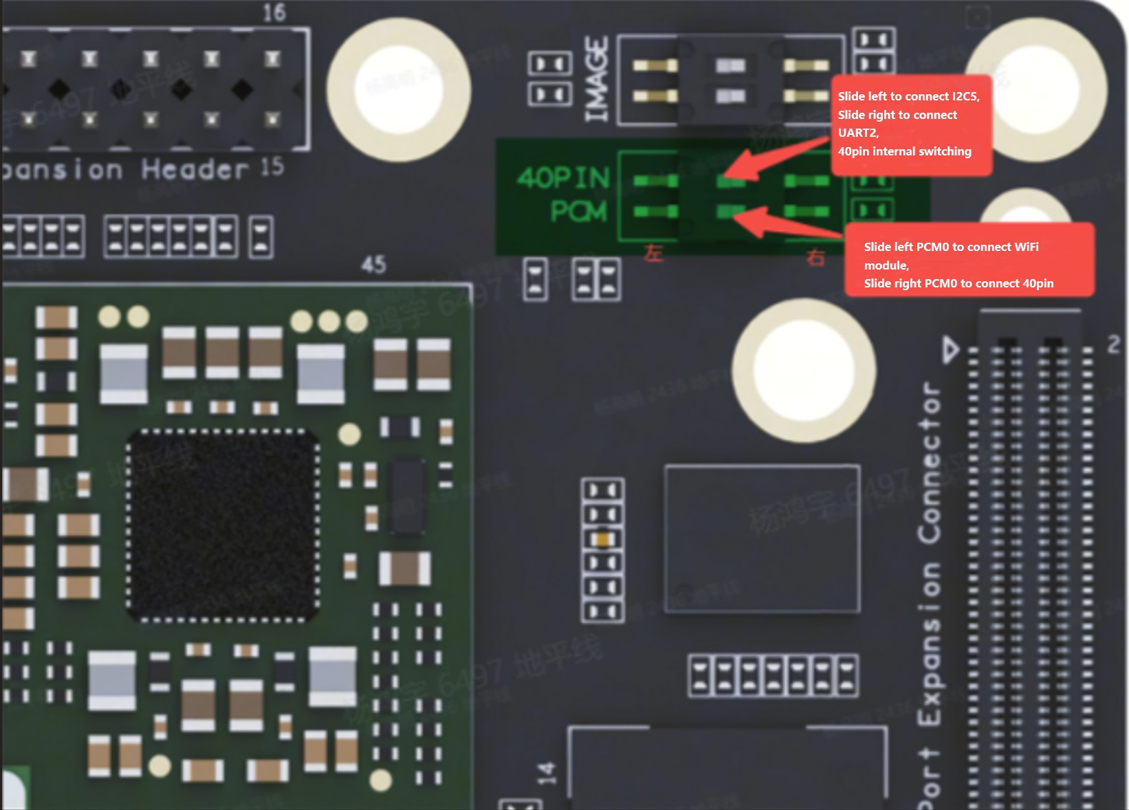
On the RDK S100 platform, 40-pin GPIO expansion is supported, with the following limitations:
- One group of pins on the
40-pinheader supports a multiplexed function (UART2 or I2C5). - PCM-related pins on the
40-pinheader require toggling DIP switches to be enabled.
For more details, refer to the diagram below:
For pin definitions, please refer to Pin Configuration and Definitions.
Before using a GPIO pin, you must configure it as follows:
To set a pin as input:
GPIO.setup(channel, GPIO.IN)
To set a pin as output:
GPIO.setup(channel, GPIO.OUT)
You can also specify an initial value for an output channel, for example:
GPIO.setup(channel, GPIO.OUT, initial=GPIO.HIGH)
Additionally, the library supports configuring multiple output channels simultaneously, for example:
# Set GPIO pins (18, 12, 13) as outputs
channels = [18, 12, 13]
GPIO.setup(channels, GPIO.OUT)
Input Operations
To read the value of a channel, use:
GPIO.input(channel)
This command returns either 0 or 1, where 0 represents GPIO.LOW and 1 represents GPIO.HIGH.
Output Operations
To set the output state of a channel, use:
GPIO.output(channel, state)
Here, state can be either GPIO.LOW or GPIO.HIGH.
Cleaning Up Pin Usage
It is recommended to clean up GPIO channels before exiting your program:
GPIO.cleanup()
To clean up only specific channels, use:
# Clean up a single channel
GPIO.cleanup(channel)
# Clean up a group of channels
GPIO.cleanup((channel1, channel2))
GPIO.cleanup([channel1, channel2])
Checking Pin Status
This feature allows you to check the current function of a GPIO channel:
GPIO.gpio_function(channel)
This function returns either IN or OUT.
Edge Detection and Interrupts
An edge refers to a transition in an electrical signal—either from low to high (rising edge) or from high to low (falling edge). Such transitions can be treated as events that trigger CPU interrupts.
On the RDK S100 platform, pins labeled PERI_GPIO on the 40-pin header do not support interrupts. Under the BOARD numbering mode, these pins are numbered: 11, 13, 15, 16, 18, 22, 29, 31, 36, and 37.
For pin definitions, please refer to Pin Configuration and Definitions.
The GPIO library provides three methods for detecting input events:
wait_for_edge() Function
This function blocks the calling thread until the specified edge transition is detected. Example usage:
GPIO.wait_for_edge(channel, GPIO.RISING)
The second parameter specifies the edge type to detect and can be one of GPIO.RISING, GPIO.FALLING, or GPIO.BOTH. You can also specify a timeout (in milliseconds):
# Timeout in milliseconds
GPIO.wait_for_edge(channel, GPIO.RISING, timeout=500)
If the signal changes within the timeout period, the function returns the channel number. If the timeout expires, it returns None.
event_detected() Function
This function allows you to periodically check whether an event has occurred since the last call. It can be set up and used as follows:
# Enable rising edge detection on the channel
GPIO.add_event_detect(channel, GPIO.RISING)
if GPIO.event_detected(channel):
    print("Rising edge event detected")
You can detect events of GPIO.RISING, GPIO.FALLING, or GPIO.BOTH.
Run a callback function when an edge event is detected
This feature can be used to register a callback function, which runs in a separate processing thread. Usage is as follows:
# define callback function
def callback_fn(channel):
    print("Callback called from channel %s" % channel)

# enable rising detection
GPIO.add_event_detect(channel, GPIO.RISING, callback=callback_fn)
If needed, you can also add multiple callbacks as shown below:
def callback_one(channel):
    print("First Callback")

def callback_two(channel):
    print("Second Callback")

GPIO.add_event_detect(channel, GPIO.RISING)
GPIO.add_event_callback(channel, callback_one)
GPIO.add_event_callback(channel, callback_two)
Since all callback functions run on the same thread, different callbacks are executed sequentially rather than concurrently.
To prevent the callback function from being called multiple times by merging multiple events into a single event, you can optionally set a debounce time:
# bouncetime unit is ms
GPIO.add_event_detect(channel, GPIO.RISING, callback=callback_fn, bouncetime=200)
Disable interrupts
If edge detection is no longer needed, you can remove it as follows:
GPIO.remove_event_detect(channel)
Test Examples
Main test examples are provided under the /app/40pin_samples/ directory:
| Test Example Name | Description |
|---|---|
| simple_out.py | Single pin output test |
| simple_input.py | Single pin input test |
| button_led.py | One pin used as button input, another controls an LED |
| button_event.py | Capture rising and falling edge events on a pin |
| button_interrupt.py | Handle rising and falling edge events via interrupts |
- GPIO configured in
output mode, toggling output level every 1 second to control an LED blinking on and off. Test code:simple_out.py:
#!/usr/bin/env python3
import sys
import signal
import Hobot.GPIO as GPIO
import time


def signal_handler(signal, frame):
    sys.exit(0)


# Define the GPIO pin used as output_pin


def determine_pins():
    board_id = GPIO.gpio_pin_data.parse_boardid()
    if GPIO.gpio_pin_data.if_s100_40pin(board_id):
        return 37
    else:
        return 26


def main():
    output_pin = determine_pins()
    # Set pin numbering mode to BOARD (physical pin numbers)
    GPIO.setmode(GPIO.BOARD)
    # Set as output mode, initialized to HIGH
    GPIO.setup(output_pin, GPIO.OUT, initial=GPIO.HIGH)
    # Track current pin state
    curr_value = GPIO.HIGH
    print("Starting demo now! Press CTRL+C to exit")
    try:
        # Toggle LED every 1 second
        while True:
            time.sleep(1)
            GPIO.output(output_pin, curr_value)
            curr_value ^= GPIO.HIGH
    finally:
        GPIO.cleanup()


if __name__ == '__main__':
    signal.signal(signal.SIGINT, signal_handler)
    main()
- GPIO configured in
input mode, reading pin voltage level via busy polling. Test code:simple_input.py:
#!/usr/bin/env python3
import sys
import signal
import Hobot.GPIO as GPIO
import time


def signal_handler(signal, frame):
    sys.exit(0)


# Define the GPIO pin used as input_pin


GPIO.setwarnings(False)


def determine_pins():
    board_id = GPIO.gpio_pin_data.parse_boardid()
    if GPIO.gpio_pin_data.if_s100_40pin(board_id):
        return 37
    else:
        return 26


def main():
    prev_value = None
    input_pin = determine_pins()
    # Set pin numbering mode to BOARD (physical pin numbers)
    GPIO.setmode(GPIO.BOARD)
    # Set as input mode
    GPIO.setup(input_pin, GPIO.IN)

    print("Starting demo now! Press CTRL+C to exit")
    try:
        while True:
            # Read pin voltage level
            value = GPIO.input(input_pin)
            if value != prev_value:
                if value == GPIO.HIGH:
                    value_str = "HIGH"
                else:
                    value_str = "LOW"
                print("Value read from pin {} : {}".format(input_pin, value_str))
                prev_value = value
            time.sleep(1)
    finally:
        GPIO.cleanup()


if __name__=='__main__':
    signal.signal(signal.SIGINT, signal_handler)
    main()
- GPIO configured in input mode to capture rising and falling edge events. Test code:
button_event.py, which detects a falling edge on pin 24 and then controls the output of pin 23:
#!/usr/bin/env python3
import sys
import signal
import Hobot.GPIO as GPIO
import time


def signal_handler(signal, frame):
    sys.exit(0)


# Define GPIO pins:
# led_pin as output to light an LED
# but_pin as input connected to a button
BOARD_ID_PATH = "/sys/class/boardinfo/adc_boardid"


# Disable warning messages
GPIO.setwarnings(False)


def determine_pins():
    board_id = GPIO.gpio_pin_data.parse_boardid()
    if GPIO.gpio_pin_data.if_s100_40pin(board_id):
        return 23, 24
    else:
        return 26, 27


def main():
```led_pin, but_pin = determine_pins()
    # Set pin numbering mode to BOARD (hardware numbering)
    GPIO.setmode(GPIO.BOARD)
    GPIO.setup(led_pin, GPIO.OUT)  # LED pin set as output
    GPIO.setup(but_pin, GPIO.IN)  # button pin set as input

    # Initial state for LEDs:
    GPIO.output(led_pin, GPIO.LOW)

    print("Starting demo now! Press CTRL+C to exit")
    try:
        while True:
            print("Waiting for button event")
            GPIO.wait_for_edge(but_pin, GPIO.FALLING)

            # event received when button pressed
            print("Button Pressed!")
            GPIO.output(led_pin, GPIO.HIGH)
            time.sleep(1)
            GPIO.output(led_pin, GPIO.LOW)
    finally:
        GPIO.cleanup()  # cleanup all GPIOs


if __name__ == '__main__':
    signal.signal(signal.SIGINT, signal_handler)
    main()
- Configure GPIO as input mode, enable GPIO interrupt functionality to respond to rising-edge and falling-edge events on the pin. The test code
button_interrupt.pyimplements the following:- Pin 15 toggles HIGH/LOW with a period of 4 seconds and a 50% duty cycle (i.e., HIGH for 2 seconds, then LOW for 2 seconds), continuously running during program execution.
- Detect falling-edge interrupts on pin 24. The interrupt handler toggles pin 16 HIGH/LOW rapidly five times. When the user pulls pin 24 LOW, pin 16 will toggle with a 1-second period and 50% duty cycle (i.e., HIGH for 0.5 seconds, then LOW for 0.5 seconds), completing a total of 5 cycles.
#!/usr/bin/env python3
import sys
import signal
import Hobot.GPIO as GPIO
import time


def signal_handler(signal, frame):
    sys.exit(0)


# Define GPIO channels to use:
# Pin 15 as output, can drive an LED
# Pin 16 as output, can drive an LED
# but_pin as input, can connect to a button
led_pin_1 = 15  # BOARD numbering 15
led_pin_2 = 16  # BOARD numbering 16

# Disable warning messages
GPIO.setwarnings(False)


def determine_pins():
    board_id = GPIO.gpio_pin_data.parse_boardid()
    if GPIO.gpio_pin_data.if_s100_40pin(board_id):
        return 24
    else:
        return 27


# When the button is pressed, LED 2 blinks rapidly 5 times
def blink(channel):
    print("Blink LED 2")
    for i in range(5):
        GPIO.output(led_pin_2, GPIO.HIGH)
        time.sleep(0.5)
        GPIO.output(led_pin_2, GPIO.LOW)
        time.sleep(0.5)


def main():
    but_pin = determine_pins()
    # Pin Setup:
    GPIO.setmode(GPIO.BOARD)  # BOARD pin-numbering scheme
    GPIO.setup([led_pin_1, led_pin_2], GPIO.OUT)  # LED pins set as output
    GPIO.setup(but_pin, GPIO.IN)  # button pin set as input

    # Initial state for LEDs:
    GPIO.output(led_pin_1, GPIO.LOW)
    GPIO.output(led_pin_2, GPIO.LOW)

    # Register the blink function as the interrupt handler for falling-edge events on the button pin
    GPIO.add_event_detect(but_pin, GPIO.FALLING, callback=blink, bouncetime=10)
    # Start demo: LED1 blinks slowly
    print("Starting demo now! Press CTRL+C to exit")
    try:
        while True:
            # blink LED 1 slowly
            GPIO.output(led_pin_1, GPIO.HIGH)
            time.sleep(2)
            GPIO.output(led_pin_1, GPIO.LOW)
            time.sleep(2)
    finally:
        GPIO.cleanup()  # cleanup all GPIOs


if __name__ == '__main__':
    signal.signal(signal.SIGINT, signal_handler)
    main()
hb_gpioinfo Tool Introduction
hb_gpioinfo is a GPIO utility tool adapted for the RDK S100, which displays the correspondence between PinName and PinNum on the current development board. Example command output is shown below:
sunrise@ubuntu:/root$ sudo hb_gpioinfo
|--- ---------------- --------------------|
|Idx|        Pin Name|            Pin Func|
|--- ---------------- --------------------|
|439|        GNSS_INT|                gpio|
|--- ---------------- --------------------|
|440|       PERI_RSTO|      Not Configured|
|--- ---------------- --------------------|
|441|        CAM_PINT|      Not Configured|
|--- ---------------- --------------------|
|442|          SD_1V8|        video_sd_1v8|
|--- ---------------- --------------------|
|443|      SD_BUS_POW|      Not Configured|
|--- ---------------- --------------------|
|444|     SENSOR0_ERR|      Not Configured|
|--- ---------------- --------------------|
|445|     SENSOR1_ERR|      Not Configured|
|--- ---------------- --------------------|
|446|     SENSOR2_ERR|      Not Configured|
|--- ---------------- --------------------|
|447|     SENSOR3_ERR|      Not Configured|
|--- ---------------- --------------------|
|448|     SENSOR4_ERR|      Not Configured|
|--- ---------------- --------------------|
|449|     SENSOR5_ERR|      Not Configured|
|--- ---------------- --------------------|
|450|     SENSOR6_ERR|      Not Configured|
|--- ---------------- --------------------|
|451|     SENSOR7_ERR|      Not Configured|
|--- ---------------- --------------------|
|452|     SENSOR8_ERR|      Not Configured|
|--- ---------------- --------------------|
|453|     SENSOR9_ERR|                gpio|
|--- ---------------- --------------------|
|454|    SENSOR10_ERR|      Not Configured|
|--- ---------------- --------------------|
|455|    SENSOR11_ERR|      Not Configured|
|--- ---------------- --------------------|
|456|     LPWM0_DOUT0|     cam_lpwm0_dout0|
|--- ---------------- --------------------|
|457|     LPWM0_DOUT1|     cam_lpwm0_dout1|
|--- ---------------- --------------------|
|458|     LPWM0_DOUT2|     cam_lpwm0_dout2|
|--- ---------------- --------------------|
|459|     LPWM0_DOUT3|     cam_lpwm0_dout3|
|--- ---------------- --------------------|
|460|     LPWM1_DOUT0|     cam_lpwm1_dout0|
|--- ---------------- --------------------|
|461|     LPWM1_DOUT1|     cam_lpwm1_dout1|
|--- ---------------- --------------------|
|462|     LPWM1_DOUT2|     cam_lpwm1_dout2|
|--- ---------------- --------------------|
|463|     LPWM1_DOUT3|     cam_lpwm1_dout3|
|--- ---------------- --------------------|
|464|        I2C0_SCL|        cam_i2c0_scl|
|--- ---------------- --------------------|
|465|        I2C0_SDA|        cam_i2c0_sda|
|--- ---------------- --------------------|
|466|        I2C1_SCL|        cam_i2c1_scl|
|--- ---------------- --------------------|
|467|        I2C1_SDA|        cam_i2c1_sda|
|--- ---------------- --------------------|
|468|        I2C2_SCL|        cam_i2c2_scl|
|--- ---------------- --------------------|
|469|        I2C2_SDA|        cam_i2c2_sda|
|--- ---------------- --------------------|
|470|        I2C3_SCL|        cam_i2c3_scl|
|--- ---------------- --------------------|
|471|        I2C3_SDA|        cam_i2c3_sda|
|--- ---------------- --------------------|
|472|        I2C4_SCL|        cam_i2c4_scl|
|--- ---------------- --------------------|
|473|        I2C4_SDA|        cam_i2c4_sda|
|--- ---------------- --------------------|
|474|       UART1_RXD|      peri_uart1_rxd|
|--- ---------------- --------------------|
|475|       PCM0_MCLK|      Not Configured|
|--- ---------------- --------------------|
|476|       PCM0_BCLK|      Not Configured|
|--- ---------------- --------------------|
|477|      PCM0_FSYNC|      Not Configured|
|--- ---------------- --------------------|
|478|      PCM0_DATA0|      Not Configured|
|--- ---------------- --------------------|
|479|      PCM0_DATA1|      Not Configured|
|--- ---------------- --------------------|
|480|   EMAC_MDC_HSI0|  peri_emac_mdc_hsi0|
|--- ---------------- --------------------|
|481|  EMAC_MDIO_HSI0| peri_emac_mdio_hsi0|
|--- ---------------- --------------------|
```|482|          SD_CLK|      Not Configured|
|--- ---------------- --------------------|
|483|          SD_CMD|      Not Configured|
|--- ---------------- --------------------|
|484|        SD_DATA0|      Not Configured|
|--- ---------------- --------------------|
|485|        SD_DATA1|      Not Configured|
|--- ---------------- --------------------|
|486|        SD_DATA2|      Not Configured|
|--- ---------------- --------------------|
|487|        SD_DATA3|      Not Configured|
|--- ---------------- --------------------|
|488|        SD_DATA4|      Not Configured|
|--- ---------------- --------------------|
|489|        SD_DATA5|      Not Configured|
|--- ---------------- --------------------|
|490|        SD_DATA6|      Not Configured|
|--- ---------------- --------------------|
|491|        SD_DATA7|      Not Configured|
|--- ---------------- --------------------|
|492|    SD_DATA_STRB|      Not Configured|
|--- ---------------- --------------------|
|493|        SD_DET_N|      Not Configured|
|--- ---------------- --------------------|
|494|        SD_WPROT|      Not Configured|
|--- ---------------- --------------------|
|495|        I2C5_SCL|       peri_i2c5_scl|
|--- ---------------- --------------------|
|496|        I2C5_SDA|       peri_i2c5_sda|
|--- ---------------- --------------------|
|497|       SPI0_CSN0|      peri_spi0_csn0|
|--- ---------------- --------------------|
|498|       SPI0_CSN1|      peri_spi0_csn1|
|--- ---------------- --------------------|
|499|       SPI0_MOSI|      peri_spi0_mosi|
|--- ---------------- --------------------|
|500|       SPI0_MISO|      peri_spi0_miso|
|--- ---------------- --------------------|
|501|       SPI0_SCLK|      peri_spi0_sclk|
|--- ---------------- --------------------|
|502|       SPI1_CSN0|      peri_spi1_csn0|
|--- ---------------- --------------------|
|503|       SPI1_CSN1|      peri_spi1_csn1|
|--- ---------------- --------------------|
|504|       SPI1_MOSI|      peri_spi1_mosi|
|--- ---------------- --------------------|
|505|       SPI1_MISO|      peri_spi1_miso|
|--- ---------------- --------------------|
|506|       SPI1_SCLK|      peri_spi1_sclk|
|--- ---------------- --------------------|
|507|       UART0_TXD|      peri_uart0_txd|
|--- ---------------- --------------------|
|508|       UART0_RXD|      peri_uart0_rxd|
|--- ---------------- --------------------|
|509|      UART0_RTSN|     peri_uart0_rtsn|
|--- ---------------- --------------------|
|510|      UART0_CTSN|     peri_uart0_ctsn|
|--- ---------------- --------------------|
|511|       UART1_TXD|      peri_uart1_txd|
|--- ---------------- --------------------|
|--- ---------------- --------------------|