V4L2 Usage
RDK X5 supports the V4L2 interface, allowing users to access the MIPI interface camera of RDK X5 via V4L2 and obtain image data at various stages such as VIN, ISP, and VSE.
Mode Switching
Use srpi-config to configure the camera capture mode.
Navigate to 3 Interface Options -> I7 V4L2
Select I1 V4L2 Enable/disable V4L2 interface for camera
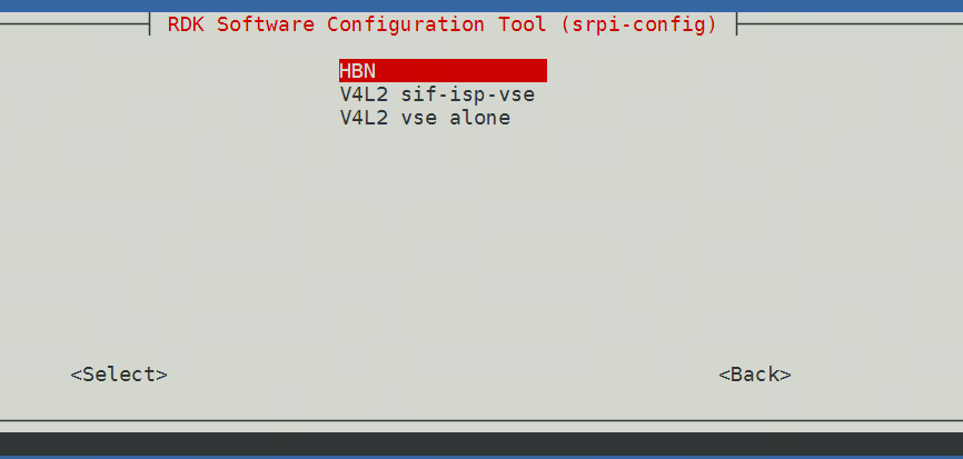
Mode Introduction
HBN Normal Mode
The camera has a separate set of APIs. Modules after the camera are abstracted as vnodes, including VIN, ISP, VSE, GDC, and Codec. Multiple vnodes form a vflow (similar to a pipeline). The camera and VIN are bound via the attach interface. Users only need to use the HBN interface for module initialization and binding. Once the vflow is established and started, users do not need to manage frame transmission; X5 will automatically pass frames downstream internally.
V4L2 sif-isp-vse V4L2 Data Stream Mode
The camera is added via the V4L2 sensor driver. VIN, ISP, and VSE provide corresponding V4L2 video device nodes, allowing users to directly obtain data via the V4L2 API.
V4L2 vse alone V4L2 VSE Standalone Mode
Provides VSE channel V4L2 video device nodes. Users can directly feed images to the VSE module for processing via the V4L2 API.
Camera Configuration
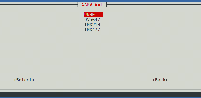
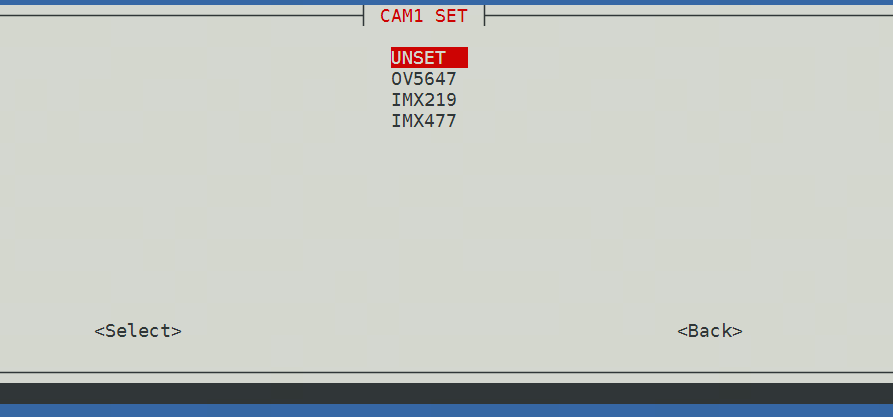
If you select sif-isp-vse, a prompt will appear to select CAM0 or CAM1.
On X5 RDK, cam0 is near the network port, cam1 is farther away.
On X5 MD, you can check the silkscreen on the carrier board.
After configuration, reboot the board.
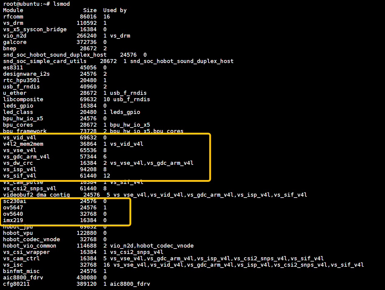
To confirm V4L2 mode is active:
Use lsmod to check drivers; you should see v4l-related and sensor-related drivers.
Device Topology
After enabling V4L2 sif-isp-vse mode, you can view the device topology with the following commands. This shows the media pipeline structure of the /dev/media0 device, including sensors, ISP, video nodes, and data flow paths.
media-ctl -d /dev/media0 --print-dot > media0.dot
dot -Tpng media0.dot -o media0.png

You can also refer to the table below:
VIDEO_DEV_CSI0_SIF "/dev/video0"
VIDEO_DEV_CSI0_ISP "/dev/video4"
VIDEO_DEV_CSI0_VSE0 "/dev/video8"
VIDEO_DEV_CSI0_VSE1 "/dev/video9"
VIDEO_DEV_CSI0_VSE2 "/dev/video10"
VIDEO_DEV_CSI0_VSE3 "/dev/video11"
VIDEO_DEV_CSI0_VSE4 "/dev/video12"
VIDEO_DEV_CSI0_VSE5 "/dev/video13"

VIDEO_DEV_CSI1_SIF "/dev/video1"
VIDEO_DEV_CSI1_ISP "/dev/video5"
VIDEO_DEV_CSI1_VSE0 "/dev/video14"
VIDEO_DEV_CSI1_VSE1 "/dev/video15"
VIDEO_DEV_CSI1_VSE2 "/dev/video16"
VIDEO_DEV_CSI1_VSE3 "/dev/video17"
VIDEO_DEV_CSI1_VSE4 "/dev/video18"
VIDEO_DEV_CSI1_VSE5 "/dev/video19"

VIDEO_DEV_CSI2_SIF "/dev/video2"
VIDEO_DEV_CSI2_ISP "/dev/video6"
VIDEO_DEV_CSI2_VSE0 "/dev/video20"
VIDEO_DEV_CSI2_VSE1 "/dev/video21"
VIDEO_DEV_CSI2_VSE2 "/dev/video22"
VIDEO_DEV_CSI2_VSE3 "/dev/video23"
VIDEO_DEV_CSI2_VSE4 "/dev/video24"
VIDEO_DEV_CSI2_VSE5 "/dev/video25"

VIDEO_DEV_CSI3_SIF "/dev/video3"
VIDEO_DEV_CSI3_ISP "/dev/video7"
VIDEO_DEV_CSI3_VSE0 "/dev/video26"
VIDEO_DEV_CSI3_VSE1 "/dev/video27"
VIDEO_DEV_CSI3_VSE2 "/dev/video28"
VIDEO_DEV_CSI3_VSE3 "/dev/video29"
VIDEO_DEV_CSI3_VSE4 "/dev/video30"
VIDEO_DEV_CSI3_VSE5 "/dev/video31"
Usage Instructions
V4L2-CTL Commands
- Use
v4l2-ctl --list-formats-extto query supported resolutions and encoding formats, and to initialize the driver. - Use
v4l2-ctl -d /dev/video4to capture video data.
v4l2-ctl --list-formats-ext --device /dev/video4
v4l2-ctl -d /dev/video4 \
        --set-fmt-video=width=640,height=480,pixelformat=NV12 \
        --stream-mmap=3 \
        --stream-skip=3 \
        --stream-to=/tmp/nv12.yuv \
        --stream-count=1 \
        --stream-poll
V4L2 Sample Code
Sample code is available at v4l2_demo.c
Parameter Description
-w Sensor output width
-h Sensor output height
-c Number of images to capture
-n Sensor capture video node
-o Input NV12 image video node
-i Input NV12 image path
- In
V4L2 sif-isp-vsemode, capture images and save to file:
./v4l2 -w 1920 -h 1080 -c 10 -n 4
- In
V4L2 vse alonemode, use the VSE node alone. Use 1080p.yuv as input, and save the scaled image to file:
./v4l2 -w 1920 -h 1080 -c 10 -n 2 -o 2 -i ./1080p.yuv
Multimedia Applications
The same sample programs are used for both hbn mode and V4L2 sif-isp-vse mode. hobot-spdev will automatically select the working mode based on the current driver, with slightly different log outputs.
Supported Examples
For HDMI display, stop the desktop first:
sudo systemctl stop lightdm
/app/cdev_demo/vio2display
/app/cdev_demo/vio_capture
/app/cdev_demo/vio2encoder
/app/cdev_demo/bpu ./sample -f /app/model/basic/yolov5s_672x672_nv12.bin -m 0
/app/pydev_demo/03_mipi_camera_sample
Known Issues
- When capturing VSE streams, the ISP sensor configuration file is forcibly set to 1920x1080 resolution.
- In
V4L2 vse alonemode, only VSE channel 2 is supported for image feeding and result retrieval.