Hardware Reference
Mechanical Installation
The GS130WI module has a mounting hole at each end. Dimensions are shown below (Unit: mm). Detailed 3D model files are available in Downloads. Use two M2.5 bolts through these mounting holes to attach the GS130WI module to other structures.
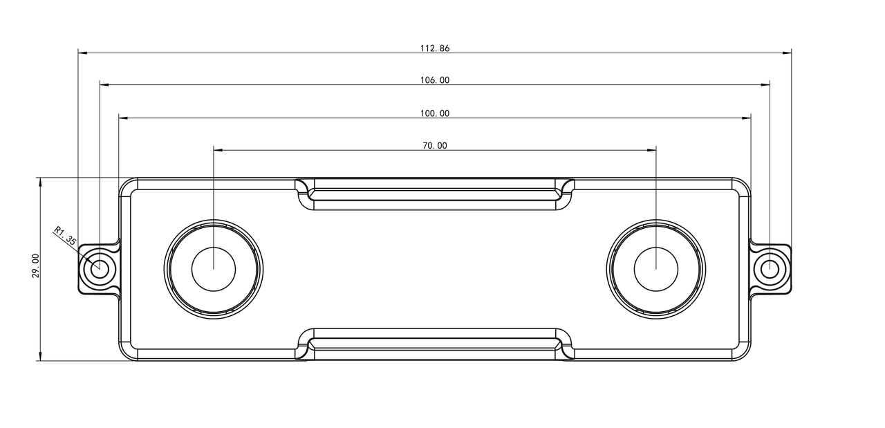
When installing, place washers at the counterbore locations and tighten the bolts alternately to avoid minor deformation of the GS130WI metal housing, which could change the external parameters of the sensor positions.
Hardware Interface Description
Hardware Topology
The diagram below shows the hardware topology between the GS130WI module and the RDK development board.

Connector Models
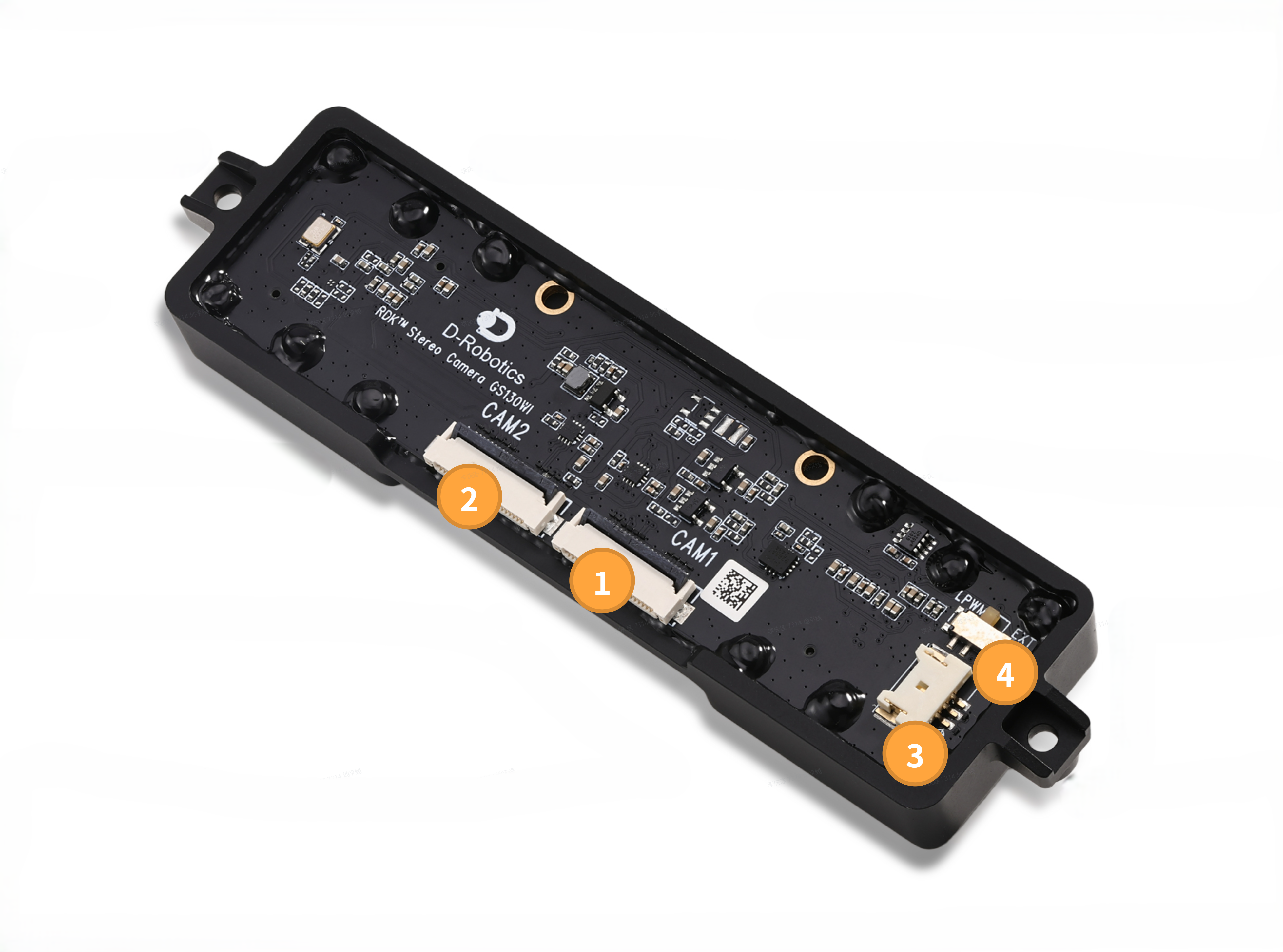
| Connector | Model | Manufacturer |
|---|---|---|
| 1 | AFC24-S22FIA-00 | JuShuo Electronics |
| 2 | AFC24-S22FIA-00 | JuShuo Electronics |
| 3 | 5063-3AWB | Wenzhang Jimei |
Interface Description
① Right MIPI Camera Interface
This interface is used for right camera and IMU data transmission.
The connector PIN1 location is shown below:

The connector pinout is shown in the table below:
| PIN | Name | Description |
|---|---|---|
| 1 | GND | |
| 2 | MDN0 | MIPI Data Negative 0, for video stream transmission |
| 3 | MDP0 | MIPI Data Positive 0, for video stream transmission |
| 4 | GND | |
| 5 | MDN1 | MIPI Data Negative 1, for video stream transmission |
| 6 | MDP1 | MIPI Data Positive 1, for video stream transmission |
| 7 | GND | |
| 8 | MCN | MIPI Clock Negative, for video stream transmission |
| 9 | MCP | MIPI Clock Positive, for video stream transmission |
| 10 | GND | |
| 11 | N/A | |
| 12 | N/A | |
| 13 | GND | |
| 14 | N/A | |
| 15 | N/A | |
| 16 | GND | |
| 17 | RESET | Connected to the Camera Sensor XSHUTDN pin for hardware reset of the sensor chip |
| 18 | FSYNC | Connected to the Camera Sensor TRIGL/FSYNC pin to enable exposure in Slave mode If the IMU interrupt selection switch is set to LPWM: connected to the IMU INT2 pin to input Fsync rising/falling edge signals to the IMU |
| 19 | GND | |
| 20 | SCL | Connected to the Camera Sensor SCL pin for sensor configuration Connected to the IMU SCL pin for IMU configuration and IMU data readout |
| 21 | SDA | Connected to the Camera Sensor SDA pin for sensor configuration Connected to the IMU SDA pin for IMU configuration and IMU data readout |
| 22 | 3V3 |
② Left MIPI Camera Interface
This interface is used for left camera data transmission.
The connector PIN1 location is the same as the right MIPI Camera interface.
The connector pinout is shown in the table below:
| PIN | Name | Description |
|---|---|---|
| 1 | GND | |
| 2 | MDN0 | MIPI Data Negative 0, for video stream transmission |
| 3 | MDP0 | MIPI Data Positive 0, for video stream transmission |
| 4 | GND | |
| 5 | MDN1 | MIPI Data Negative 1, for video stream transmission |
| 6 | MDP1 | MIPI Data Positive 1, for video stream transmission |
| 7 | GND | |
| 8 | MCN | MIPI Clock Negative, for video stream transmission |
| 9 | MCP | MIPI Clock Positive, for video stream transmission |
| 10 | GND | |
| 11 | N/A | |
| 12 | N/A | |
| 13 | GND | |
| 14 | N/A | |
| 15 | N/A | |
| 16 | GND | |
| 17 | RESET | Connected to the Camera Sensor XSHUTDN pin for hardware reset of the sensor chip |
| 18 | FSYNC | Connected to the Camera Sensor TRIGL/FSYNC pin to enable exposure in Slave mode |
| 19 | GND | |
| 20 | SCL | Connected to the Camera Sensor SCL pin for sensor configuration |
| 21 | SDA | Connected to the Camera Sensor SDA pin for sensor configuration |
| 22 | 3V3 |
③ External Interrupt Interface
This interface is used for receiving interrupt signals from the IMU or sending interrupt signals to the IMU.
The connector PIN1 location is shown below:

The connector pinout is shown in the table below:
| PIN | Name | Description |
|---|---|---|
| 1 | INT1 | Connected to the IMU INT1 pin to route this pin function externally |
| 2 | INT2 | If the IMU interrupt selection switch is set to LPWM: N/A If the IMU interrupt selection switch is set to EXT: connected to the IMU INT2 pin to route this pin function externally |
| 3 | GND |
④ IMU Interrupt Selection Switch
This switch switches the interrupt connection of the IMU INT2 pin (PIN9).
- When the switch is set to LPWM: the IMU INT2 pin is connected to the right camera TRIGL/FSYNC pin, and external interrupt interface PIN2 is floating.
- When the switch is set to EXT: the IMU INT2 pin is connected to external interrupt interface PIN2.