Installation Guide
Required Items
Prepare the following items to install the module:
| Item | Image |
|---|---|
| GS130W module |  |
| Development board (supported board from Compatible Boards) |  |
| FFC/FPC cables x2 (22-pin, 0.5 mm pitch, same-side contacts) |  |
Installation and Connection
Connect FFC/FPC Cables to the GS130W Module
Note
- Power off the development board before connecting FFC/FPC cables to avoid device damage caused by electrical arcing or misaligned contacts.
- FFC/FPC cables are flexible; do not pull them forcefully.
- The main PCB of the GS130W module is exposed. Avoid dropping metal objects onto it during installation and use to prevent short circuits.
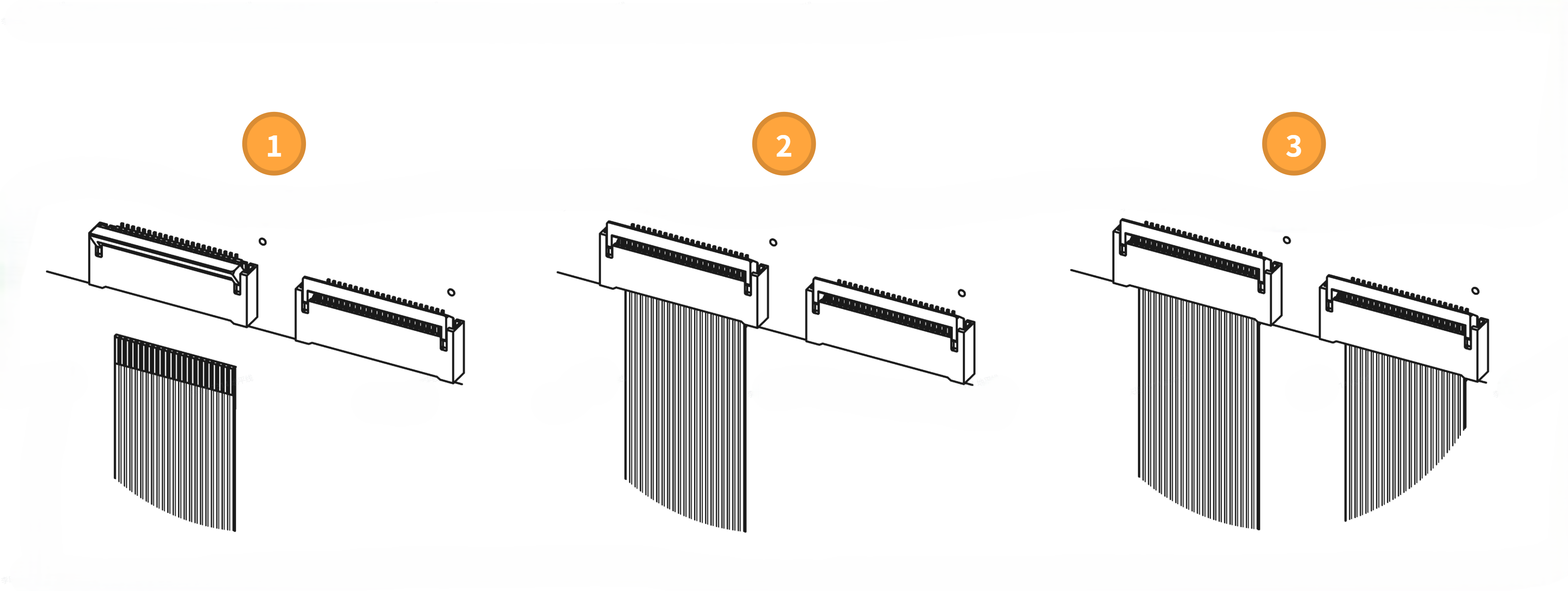
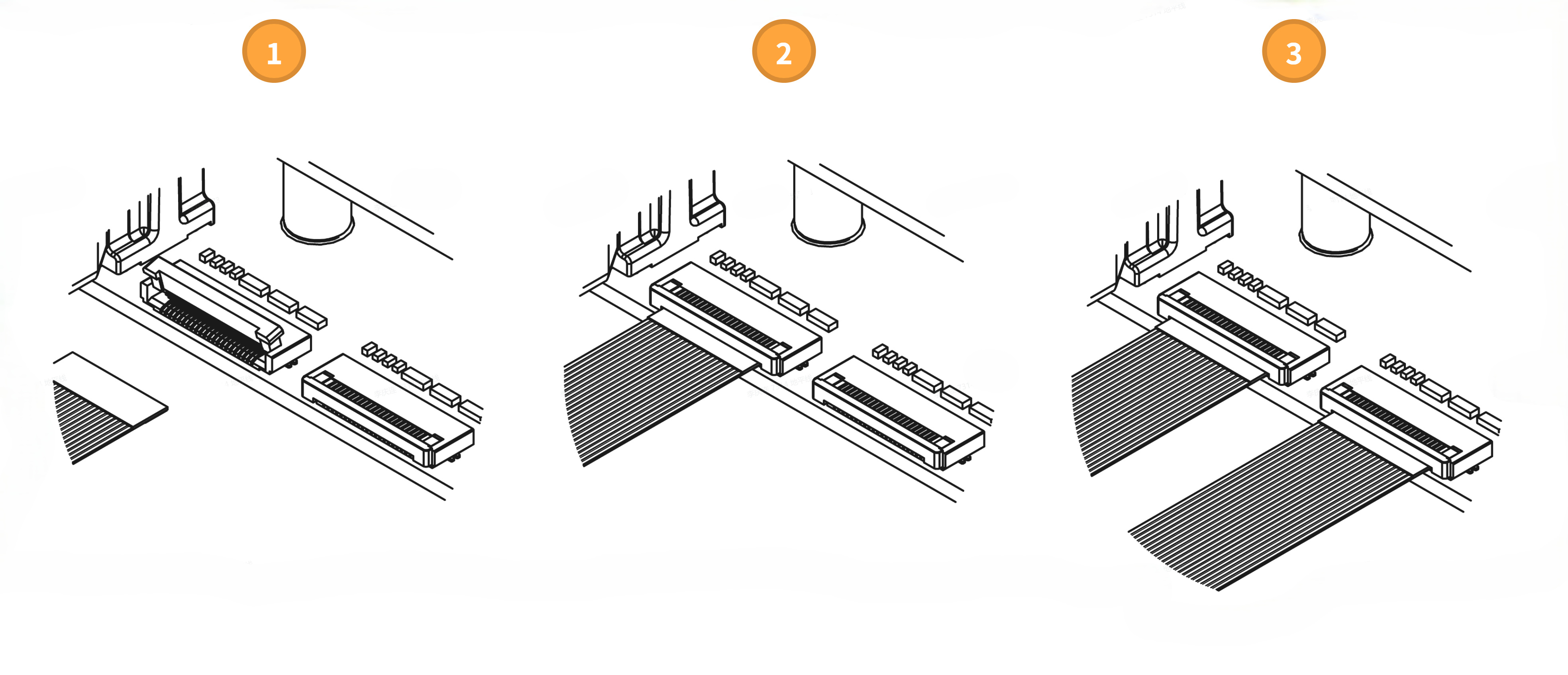
- Open the MIPI Camera connector latch on the GS130W module.
- Insert one end of the FFC/FPC cable horizontally into the MIPI Camera connector with the contacts facing away from the PCB, then press the latch closed.
- Repeat for the second FFC/FPC cable to complete the connection between the FFC/FPC cables and the GS130W module MIPI Camera interfaces.
Note
The FFC/FPC cable insertion direction for the GS130W module is opposite to that of the GS130WI module. Take care to distinguish them and avoid reverse connection.
Connect FFC/FPC Cables to the Development Board
- RDK X5
- RDK X5 Module
- RDK S100/S100P
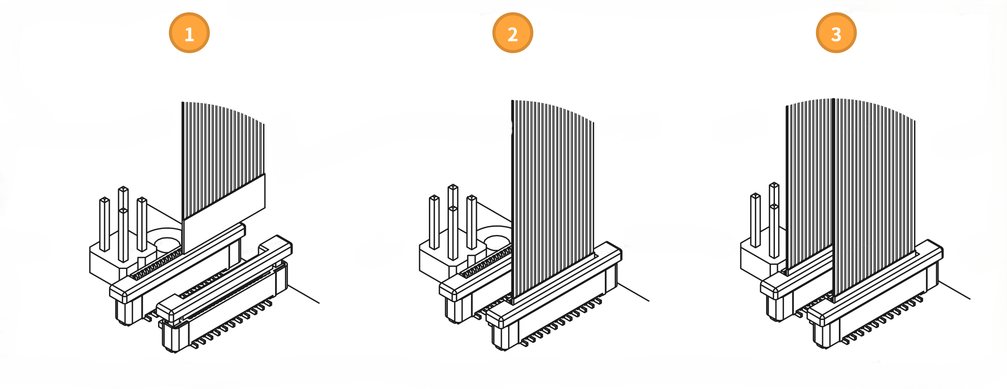
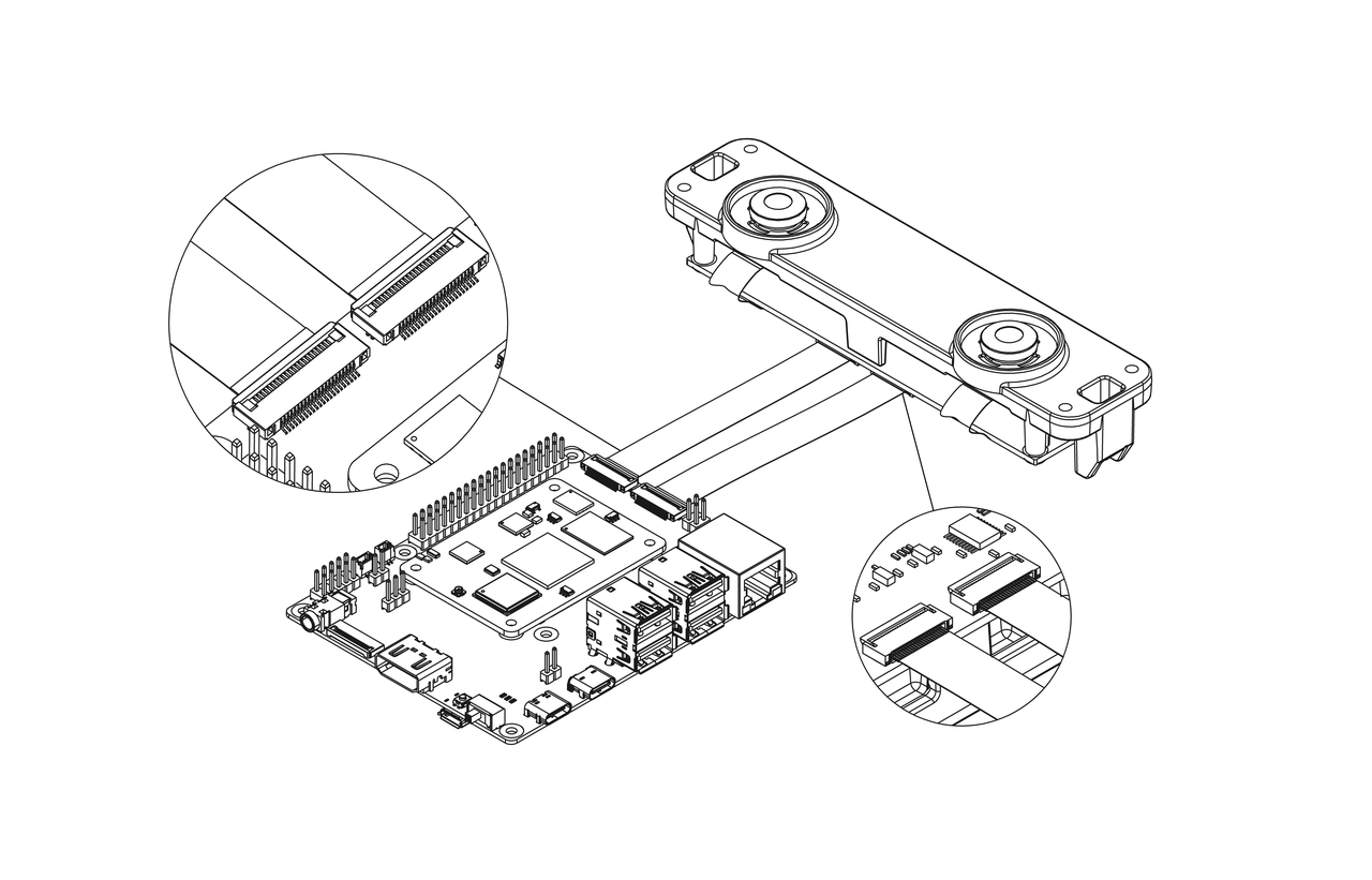
- Open the MIPI Camera connector latch on the RDK X5.
- Insert the other end of the FFC/FPC cable vertically into the MIPI Camera connector with the contacts facing toward the Ethernet port, then press the connector latch closed.
- Repeat for the second FFC/FPC cable to complete the connection between the FFC/FPC cables and the RDK X5 MIPI Camera interfaces.
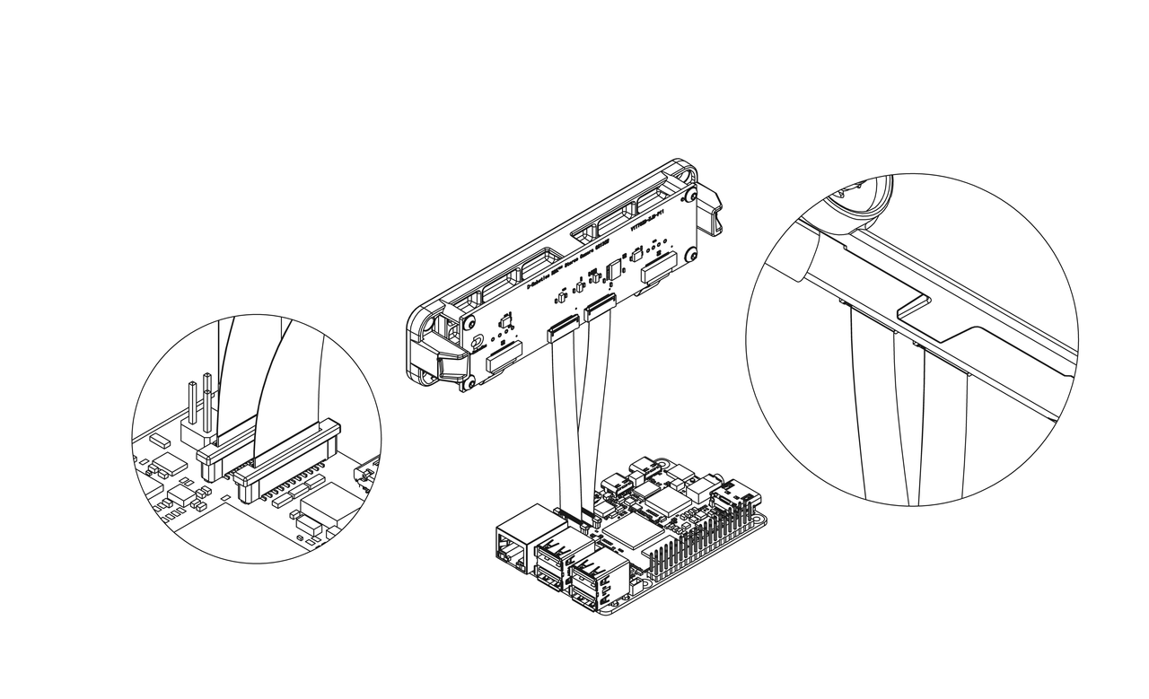
After installation, the overall connection of the GS130W module, RDK X5, and FFC/FPC cables is shown below.
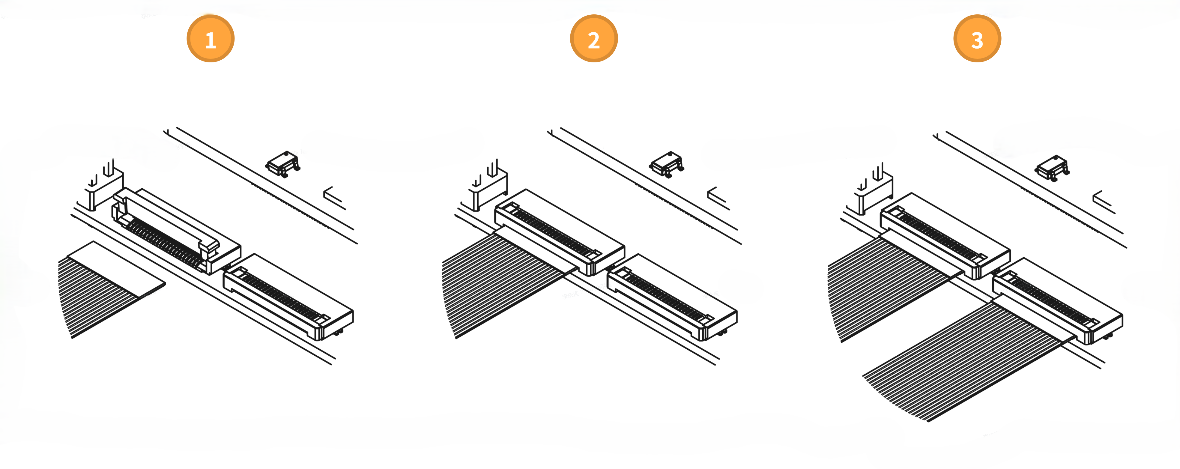
- Open the MIPI Camera connector latch on the RDK X5 Module carrier board;
- Insert the other end of the FFC/FPC cable horizontally into the MIPI connector with the contacts facing toward the PCB, then press the connector latch closed;
- Repeat for the second FFC/FPC cable to complete the connection between the FFC/FPC cables and the RDK X5 Module carrier board MIPI Camera interfaces.
After installation, the overall connection of the GS130W module, RDK X5 Module, and FFC/FPC cables is shown below.
- Open the MIPI Camera connector latch on the RDK S100 with the Camera expansion board installed;
- Insert the other end of the FFC/FPC cable horizontally into the MIPI Camera connector with the contacts facing toward the PCB, then press the connector latch closed;
- Repeat for the second FFC/FPC cable to complete the connection between the FFC/FPC cables and the RDK S100 MIPI Camera interfaces.
After installation, the overall connection of the GS130W module, RDK S100, and FFC/FPC cables is shown below.