7.5.3 MCU 系统说明
编译系统基本说明
MCU 的编译系统基于 Scons3.0.0创建(Scons 3.0.0用户手册官网)。
MCU1编译系统
MCU1 编译系统位于 mcu/Build/FreeRtos_mcu1,具体目录结构,如下图所示:
FreeRtos_mcu1
├── build_freertos.py                   # 编译的入口脚本
├── SConstruct                          # Scons 编译定义文件(统一入口)
├── build_config                        # 编译所需 yaml 文件,增删编译文件夹
│    └── S100
│         └── lite-matrix-B-mcu1.yaml
├── setting_files                       # gcc 编译链接等参数
│    └── gcc
│         └── settings_lite_freertos.py
├── site_scons                          # Scons 编译链接命令文件
│    └── site_tools
│         └── gcc_arm.py
└── Linker                              # 链接脚本所在目录
     └── gcc
          └── S100
               └── link_freertos_mcu1.ld
MCU1 编译系统位于 mcu/Build/FreeRtos_mcu1,具体目录结构,如下图所示:
FreeRtos_mcu1
├── build_freertos.py                   # 编译的入口脚本
├── SConstruct                          # Scons 编译定义文件(S600 统一入口)
├── build_config                        # 编译所需 yaml 文件,增删编译文件夹
     └── S600
         └── lite-matrix-B-mcu1.yaml
├── settings_files                      # gcc 编译链接等参数
     └── gcc
         └── settings_lite_freertos.py
├── site_scons                          # Scons 编译链接命令文件
     └── site_tools
         └── gcc_arm.py
└── Linker                              # 链接脚本所在目录
     └── gcc
         └── S600
             └── link_freertos_mcu1.ld
编译流程介绍
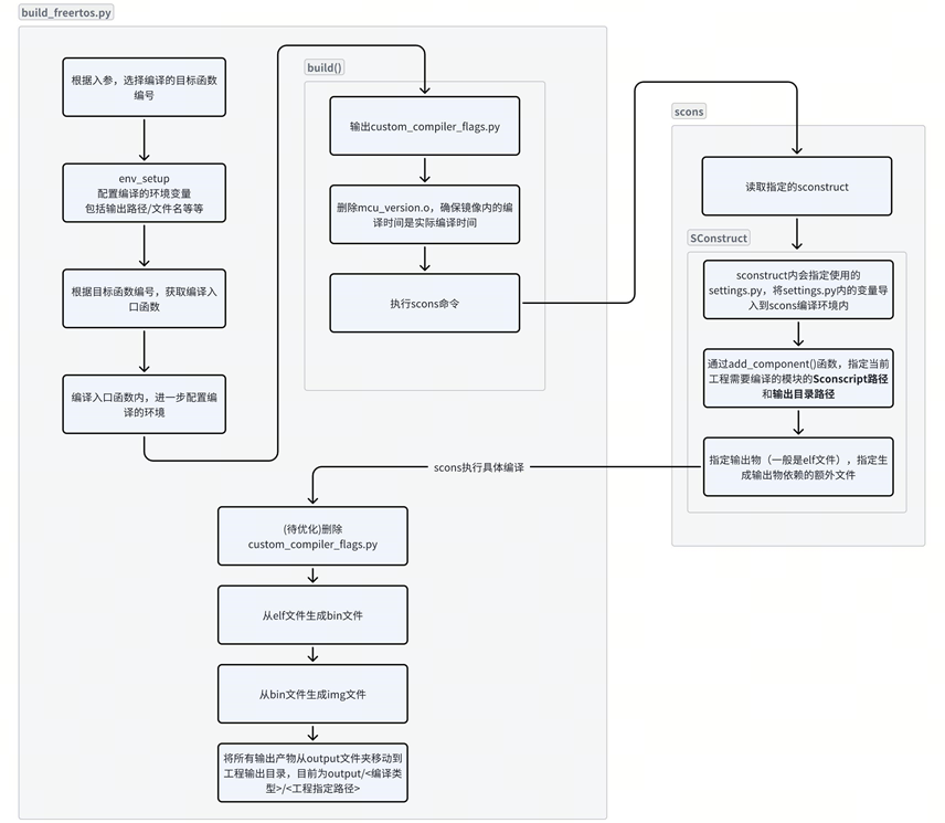
编译中的重点文件关系介绍
build_freertos.py 是编译的整体入口,但是实际调度到 scons 时,能够对 scons 编译环境/流程产生影响的方式有以下几个:
-
SConstruct文件:SConstruct是 scons 编译的定义文件,它和每个模块内的SConscript组成完整的构建入口。 -
setting_files/gcc/settings_lite_freertos.py:该文件生效入口是SConstruct中Variables类的初始化,核心在于引入一系列静态定义的编译环境变量。环境变量名和值来自settings_lite_freertos.py中的定义。 -
site_scons/site_tools/gcc_arm.py:实际定义 gcc 编译、汇编、链接命令的文件。真正生效入口是settings_lite_freertos.py里定义的COMPILER_TOOL字段,该字段会被SConstruct的Variables添加并最终被 env 获取。 -
build_config/S100/lite-matrix-B-mcu1.yaml:S100 MCU1 lite 编译使用的 yaml 配置文件。该文件中的SettingFile指向Build/FreeRtos_mcu1/setting_files/__COMPILER__/settings_lite_freertos.py,LinkFIle指向Build/FreeRtos_mcu1/Linker/__COMPILER__/S100/link_freertos_mcu1.ld,BuildPath、StaticLibCommonPath、StaticLibMcalCddPath、StaticLibPlatformPath、StaticLibServicePath等字段用于控制参与编译的目录。
build_freertos.py 是编译的整体入口,但是实际调度到 scons 时,能够对 scons 编译环境/流程产生影响的方式有以下几个:
- SConstruct 文件:SConstruct 文件是 scons 编译的定义文件,它和每个模块内的 Sconscript 组成了 Cmake 里 Cmakefile;Make 系统里 makefile 的作用;
- settings_lite_freertos.py:该文件生效的入口实际上是 SConstruct 里面的“Variables”类的初始化,核心在于引入一系列静态定义的编译环境变量;环境变量的变量名就是 settings_lite_freertos.py 里面的变量名,变量值就是 settings_lite_freertos.py 里面的变量名对应的变量值;“Variables”类实例化后的示例会被 Environment 类使用,用于 scons 的编译
- gcc_arm.py:实际定义编译命令的定义文件,真正生效的入口是 settings_lite_freertos.py 里面定义的“COMPILER_TOOL”字段,COMPILER_TOOL 字段进一步会被 Sconscruct 文件的 Variables 添加并最后被 env 获取到其中的“CC”等配置
- lite-matrix-B-mcu1.yaml:被编译的文件夹,在该文件中增删编译涉及到的文件夹;其中
LinkFIle字段指向Linker/gcc/S600/link_freertos_mcu1.ld
MCU1镜像 layout
| 区域名称 | 起始地址 | 占用大小 | 作用 |
|---|---|---|---|
| FLASH_STARTUP | 0x0CAB0000 | 2K | 启动代码、异常向量表等 |
| FLASH | 0x0CAB0800 | 2154K | 代码、数据、栈等使用的区域(不含 Can) |
| FREERTOS_HEAP | 0x0CCCB000 | 512K | FreeRTOS 堆空间 |
| CAN_Reserved | 0x0CD4B000 | 64K | Can 模块代码、数据的加载区域 |
| LOG_SHARE_Reserved | 0x0CD5B000 | 8K | MCU1 log 存放的空间,log 会循环覆盖 |
| SCMI_IPC_Reserved | 0x0CD5D000 | 12K | SCMI IPC 通信需要的空间,用于 buffer 及关键数据 |
| ATCM_Reserved | 0x0A000000 | 64K | Can 模块代码、数据的运行使用区域 |
在上述内存排布中,强烈不建议客户修改 LOG_SHARE_Reserved、SCMI_IPC_Reserved、FREERTOS_HEAP 等区域,以及链接脚本中定义的 MCU_STATE_START_ADDR(0x0C800800)等 MCU0/MCU1 共享关键地址。ATCM_Reserved 用于 Can 运行时数据,修改需谨慎。若要调整 FLASH、CAN_Reserved 等区域,请先咨询地瓜相关支持人员。
下面是地瓜版本中的链接文件(Linker/gcc/S100/link_freertos_mcu1.ld),解释了链接脚本中提供的一些变量作用:
MEMORY
{
    FLASH_STARTUP(rx)       : org = 0x0CAB0000, len = 2K
    FLASH(rw)               : org = 0x0CAB0800, len = 2154K
    FREERTOS_HEAP(rw)       : org = 0x0CCCB000, len = 512K
    CAN_Reserved(rw)        : org = 0x0CD4B000, len = 64K
    LOG_SHARE_Reserved(rw)  : org = 0x0CD5B000, len = 8K
    SCMI_IPC_Reserved(rw)   : org = 0x0CD5D000, len = 12K
    ATCM_Reserved(rw)       : org = 0x0A000000, len = 64K
}

/* Define output sections */
SECTIONS
{
    .EL2_core_exceptions_table :
    {
        . = ALIGN(32);
        _start = .;
        *(.EL2_core_exceptions_table)
        . = ALIGN(32);
    } > FLASH_STARTUP

    .EL2_Reset_Handler :
    {
        . = ALIGN(32);
        *(.EL2_Reset_Handler)
        . = ALIGN(32);
    } > FLASH_STARTUP

    .EL1_core_exceptions_table :
    {
		. = ALIGN(32);
        *(.EL1_core_exceptions_table)
        . = ALIGN(32);
    } > FLASH_STARTUP

    .EL1_core_exceptions_table_MCU2 :
    {
        . = ALIGN(32);
        *(.EL1_core_exceptions_table_MCU2)
        . = ALIGN(32);
    } > FLASH_STARTUP

    .text :
    {
        . = ALIGN(4);
        *(.text .text.*)          /* .text sections (code) */
        . = ALIGN(4);
    } > FLASH

    .shell :
    {
        _shell_command_start = .;
        KEEP (*(shellCommand))
        _shell_command_end = .;
    } > FLASH

    .mcal_text :
    {
        *(.mcal_text)
    } > FLASH

    .mcal_const_cfg :
    {
        *(.mcal_const_cfg)
    } > FLASH

    .mcal_const :
    {
        *(.mcal_const)
    } > FLASH

    .common_text :
    {
        *(.common_text)
        PROVIDE(__TEXT_END = .);
    } > FLASH
    /******************text end******************/

    .const :
    {
        . = ALIGN(32);
        *(.const)
        *(.rodata .rodata.*)
    } > FLASH


    .heap :
    {
        . = ALIGN(64);
        __HEAP_START = .;
        __end__ = .;
        __heap_start__ = .;
        PROVIDE(end = .);
        PROVIDE(_end = .);
        PROVIDE(__end = .);
        __HeapBase = .;
        . += HEAP_SIZE;
        __HeapLimit = .;
        __heap_limit = .;
        __heap_end__ = .;
    } > FLASH

    .u_boot_list :
    {
        . = ALIGN(4);
        *(SORT(.u_boot_list*))
        . = ALIGN(4);
     } > FLASH

    .global_data :
    {
        . = ALIGN(64);
        __DATA_RAM = .;
        __data_start__ = .;      /* Create a global symbol at data start. */
        *(.data .data.*)         /* .data sections */
        . = ALIGN(64);
        __data_end__ = .;        /* Define a global symbol at data end. */
        PROVIDE(__DATA_END = .);
        PROVIDE(__DATA_ROM = .);
    } > FLASH

    .stack (NOLOAD) :
    {
        . = ALIGN(64);
        __STACK_START = .;
        __StackLimit = .;
        __stack_start__ = .;
        . += STACK_SIZE;
        __stack_end__ = .;
        __StackTop = .;
    } > FLASH

    .stack_mcu2 (NOLOAD) :
    {
        . = ALIGN(64);
        __STACK_START_MCU2 = .;
        __StackLimit_MCU2 = .;
        __stack_start_mcu2__ = .;
        . += STACK_SIZE_MCU2;
        __stack_end_mcu2__ = .;
        __StackTop_MCU2 = .;
    } > FLASH

    .stack_exc (NOLOAD) :
    {
        . = ALIGN(64);
        __StackLimit_exc = .;
        __stack_start_exc__ = .;
        . += STACK_SIZE_EXC;
        __stack_end_exc__ = .;
        __StackTop_exc = .;
        __STACK_END = .;
    } > FLASH

    .stack_exc_mcu2 (NOLOAD) :
    {
        . = ALIGN(64);
        __StackLimit_exc_MCU2 = .;
        __stack_start_exc_mcu2__ = .;
        . += STACK_SIZE_EXC_MCU2;
        __stack_end_exc_mcu2__ = .;
        __StackTop_exc_MCU2 = .;
        __STACK_END_MCU2 = .;
    } > FLASH

    .init_table :
    {
      . = ALIGN(64);
      __COPY_TABLE = .;
      KEEP(*(.init_table))
    } > FLASH

    .zero_table :
    {
      . = ALIGN(64);
      __ZERO_TABLE = .;
      KEEP(*(.zero_table))
    } > FLASH

    .interrupts :
    {
        __VECTOR_TABLE = .;
        __interrupts_start__ = .;
        . = ALIGN(4);
        KEEP(*(.isr_vector))     /* Startup code */
        __interrupts_end__ = .;
        . = ALIGN(4);
    } > FLASH

  __VECTOR_RAM = __VECTOR_TABLE;
  __RAM_VECTOR_TABLE_SIZE = 0x0;
  __VECTOR_TABLE_COPY_END = __VECTOR_TABLE + __RAM_VECTOR_TABLE_SIZE;


    .interrupt_drv_shared_memory :
    {
      *(.interrupt_drv_shared_memory)
    } > FLASH

    .handlers :
    {
        . = ALIGN(32);
      *(.handlers)
    } > FLASH

    .mcal_data :
    {
        *(.mcal_data)
    } > FLASH

    .mcal_shared_data :
    {
        *(.mcal_shared_data)
    } > FLASH

    .bss (NOLOAD) :
    {
        . = ALIGN(64);
        __BSS_START = .;
        __bss_start__ = .;
        *(.bss .bss.*)
    } > FLASH

    .mcal_bss (NOLOAD) :
    {
        . = ALIGN(64);
        *(.mcal_bss)
    } > FLASH

    .mcal_shared_bss (NOLOAD) :
    {
        . = ALIGN(64);
        *(.mcal_shared_bss)
        __DATA_RAM_END = .;
        __m_ram_init_end = .;
        __bss_end__ = .;
        __BSS_END = .;
    } > FLASH

    .ipc_mdma :
    {
        *(.ipc_mdma)
    } > FLASH

    .ucheap_section (NOLOAD) :
    {
        . = ALIGN(64);
        KEEP(*(.ucheap_section))
        . = ALIGN(64);
    } > FREERTOS_HEAP

    .log (NOLOAD) :
    {
        *(.log)
    } > LOG_SHARE_Reserved

    .tcm_code :
    {
        KEEP(*(.tcm_code))
        KEEP(*(.tcm_data))
    } > ATCM_Reserved

    /*-------- LABELS USED IN CODE -------------------------------*/
    SRAM_START_ADDR         = ORIGIN(FLASH_STARTUP);
    FLASH_STARTUP_LEN       = LENGTH(FLASH_STARTUP);
    FLASH_SEC_ADDR          = ORIGIN(FLASH);
    MCU_LOG_START_ADDR      = ORIGIN(LOG_SHARE_Reserved);
    MCU_LOG_SIZE            = LENGTH(LOG_SHARE_Reserved);
    __SCMI_IPC_START_ADDR   = ORIGIN(SCMI_IPC_Reserved);
    __SCMI_IPC_SIZE         = LENGTH(SCMI_IPC_Reserved);
    NON_SECURE_START_ADDR   = ORIGIN(LOG_SHARE_Reserved);
    CAN_START_ADDR          = ORIGIN(CAN_Reserved);
    ATCM_START_ADDR         = ORIGIN(ATCM_Reserved);
    ATCM_SIZE               = LENGTH(ATCM_Reserved);
    OS_HEAP_START_ADDR      = ORIGIN(FREERTOS_HEAP);
    OS_HEAP_SIZE            = LENGTH(FREERTOS_HEAP);

    PROVIDE(SRAM_SIZE = 0x34FFFF);
    PROVIDE(MCU0_LOG_START_ADDR = 0x0CAAB000); /* Base addr from MCU0 link region "LOG_SHARE_Reserved" */
    PROVIDE(MCU_STATE_START_ADDR = 0x0C800800);/* Base addr from MCU0 link region "MCU_STATE_Reserved" */
}
| 区域名称 | 起始地址 | 占用大小 | 作用 |
|---|---|---|---|
| FLASH_STARTUP | 0x0CAB0000 | 2K | 启动代码、异常向量表等 |
| FLASH | 0x0CAB0800 | 2666K | 代码、数据、栈等使用的区域(不含 Can) |
| CAN_Reserved | 0x0CD4B000 | 64K | Can 模块代码、数据的加载区域 |
| LOG_SHARE_Reserved | 0x0CD5B000 | 8K | MCU1 log 存放的空间,log 会循环覆盖 |
| SCMI_IPC_Reserved | 0x0CD5D000 | 12K | SCMI IPC 通信需要的空间,用于 buffer 及关键数据 |
| FREERTOS_HEAP | 0x0CE00000 | 512K | FreeRTOS 堆空间 |
| ATCM_Reserved | 0x0A000000 | 64K | Can 模块代码、数据的运行使用区域 |
在上述内存排布中,强烈不建议客户修改 LOG_SHARE_Reserved、SCMI_IPC_Reserved、FREERTOS_HEAP 等区域,以及链接脚本中定义的 MCU_STATE_START_ADDR(0x0C800800)等 MCU0/MCU1 共享关键地址。ATCM_Reserved 用于 Can 运行时数据,修改需谨慎。若要调整 FLASH、CAN_Reserved 等区域,请先咨询地瓜相关支持人员。
下面是地瓜版本中的链接文件(Linker/gcc/S600/link_freertos_mcu1.ld),解释了链接脚本中提供的一些变量作用:
MEMORY
{
    FLASH_STARTUP(rx)       : org = 0x0CAB0000, len = 2K
    FLASH(rw)               : org = 0x0CAB0800, len = 2666K
    CAN_Reserved(rw)        : org = 0x0CD4B000, len = 64K
    LOG_SHARE_Reserved(rw)  : org = 0x0CD5B000, len = 8K
    SCMI_IPC_Reserved(rw)   : org = 0x0CD5D000, len = 12K
    FREERTOS_HEAP(rw)       : org = 0x0CE00000, len = 512K
    ATCM_Reserved(rw)       : org = 0x0A000000, len = 64K
}

/* Define output sections */
SECTIONS
{
    .EL2_core_exceptions_table :
    {
        . = ALIGN(32);
        _start = .;
        *(.EL2_core_exceptions_table)
        . = ALIGN(32);
    } > FLASH_STARTUP

    .EL2_Reset_Handler :
    {
        . = ALIGN(32);
        *(.EL2_Reset_Handler)
        . = ALIGN(32);
    } > FLASH_STARTUP

    .EL1_core_exceptions_table :
    {
		. = ALIGN(32);
        *(.EL1_core_exceptions_table)
        . = ALIGN(32);
    } > FLASH_STARTUP

    .EL1_core_exceptions_table_MCU2 :
    {
        . = ALIGN(32);
        *(.EL1_core_exceptions_table_MCU2)
        . = ALIGN(32);
    } > FLASH_STARTUP

    .text :
    {
        . = ALIGN(4);
        *(.text .text.*)          /* .text sections (code) */
        . = ALIGN(4);
    } > FLASH

    .shell :
    {
        _shell_command_start = .;
        KEEP (*(shellCommand))
        _shell_command_end = .;
    } > FLASH

    .mcal_text :
    {
        *(.mcal_text)
    } > FLASH

    .mcal_const_cfg :
    {
        *(.mcal_const_cfg)
    } > FLASH

    .mcal_const :
    {
        *(.mcal_const)
    } > FLASH

    .common_text :
    {
        *(.common_text)
        PROVIDE(__TEXT_END = .);
    } > FLASH
    /******************text end******************/

    .const :
    {
        . = ALIGN(32);
        *(.const)
        *(.rodata .rodata.*)
    } > FLASH


    .heap :
    {
        . = ALIGN(64);
        __HEAP_START = .;
        __end__ = .;
        __heap_start__ = .;
        PROVIDE(end = .);
        PROVIDE(_end = .);
        PROVIDE(__end = .);
        __HeapBase = .;
        . += HEAP_SIZE;
        __HeapLimit = .;
        __heap_limit = .;
        __heap_end__ = .;
    } > FLASH

    .u_boot_list :
    {
        . = ALIGN(4);
        *(SORT(.u_boot_list*))
        . = ALIGN(4);
     } > FLASH

    .global_data :
    {
        . = ALIGN(64);
        __DATA_RAM = .;
        __data_start__ = .;      /* Create a global symbol at data start. */
        *(.data .data.*)         /* .data sections */
        . = ALIGN(64);
        __data_end__ = .;        /* Define a global symbol at data end. */
        PROVIDE(__DATA_END = .);
        PROVIDE(__DATA_ROM = .);
    } > FLASH

    .stack (NOLOAD) :
    {
        . = ALIGN(64);
        __STACK_START = .;
        __StackLimit = .;
        __stack_start__ = .;
        . += STACK_SIZE;
        __stack_end__ = .;
        __StackTop = .;
    } > FLASH

    .stack_mcu2 (NOLOAD) :
    {
        . = ALIGN(64);
        __STACK_START_MCU2 = .;
        __StackLimit_MCU2 = .;
        __stack_start_mcu2__ = .;
        . += STACK_SIZE_MCU2;
        __stack_end_mcu2__ = .;
        __StackTop_MCU2 = .;
    } > FLASH

    .stack_exc (NOLOAD) :
    {
        . = ALIGN(64);
        __StackLimit_exc = .;
        __stack_start_exc__ = .;
        . += STACK_SIZE_EXC;
        __stack_end_exc__ = .;
        __StackTop_exc = .;
        __STACK_END = .;
    } > FLASH

    .stack_exc_mcu2 (NOLOAD) :
    {
        . = ALIGN(64);
        __StackLimit_exc_MCU2 = .;
        __stack_start_exc_mcu2__ = .;
        . += STACK_SIZE_EXC_MCU2;
        __stack_end_exc_mcu2__ = .;
        __StackTop_exc_MCU2 = .;
        __STACK_END_MCU2 = .;
    } > FLASH

    .init_table :
    {
      . = ALIGN(64);
      __COPY_TABLE = .;
      KEEP(*(.init_table))
    } > FLASH

    .zero_table :
    {
      . = ALIGN(64);
      __ZERO_TABLE = .;
      KEEP(*(.zero_table))
    } > FLASH

    .interrupts :
    {
        __VECTOR_TABLE = .;
        __interrupts_start__ = .;
        . = ALIGN(4);
        KEEP(*(.isr_vector))     /* Startup code */
        __interrupts_end__ = .;
        . = ALIGN(4);
    } > FLASH

  __VECTOR_RAM = __VECTOR_TABLE;
  __RAM_VECTOR_TABLE_SIZE = 0x0;
  __VECTOR_TABLE_COPY_END = __VECTOR_TABLE + __RAM_VECTOR_TABLE_SIZE;


    .interrupt_drv_shared_memory :
    {
      *(.interrupt_drv_shared_memory)
    } > FLASH

    .handlers :
    {
        . = ALIGN(32);
      *(.handlers)
    } > FLASH

    .mcal_data :
    {
        *(.mcal_data)
    } > FLASH

    .mcal_shared_data :
    {
        *(.mcal_shared_data)
    } > FLASH

    .bss (NOLOAD) :
    {
        . = ALIGN(64);
        __BSS_START = .;
        __bss_start__ = .;
        *(.bss .bss.*)
    } > FLASH

    .mcal_bss (NOLOAD) :
    {
        . = ALIGN(64);
        *(.mcal_bss)
    } > FLASH

    .mcal_shared_bss (NOLOAD) :
    {
        . = ALIGN(64);
        *(.mcal_shared_bss)
        __DATA_RAM_END = .;
        __m_ram_init_end = .;
        __bss_end__ = .;
        __BSS_END = .;
    } > FLASH

    .ipc_mdma :
    {
        *(.ipc_mdma)
    } > FLASH

    .ucheap_section (NOLOAD) :
    {
        . = ALIGN(64);
        KEEP(*(.ucheap_section))
        . = ALIGN(64);
    } > FREERTOS_HEAP

    .log (NOLOAD) :
    {
        *(.log)
    } > LOG_SHARE_Reserved

    .tcm_code :
    {
        KEEP(*(.tcm_code))
        KEEP(*(.tcm_data))
    } > ATCM_Reserved

    /*-------- LABELS USED IN CODE -------------------------------*/
    SRAM_START_ADDR         = ORIGIN(FLASH_STARTUP);
    FLASH_STARTUP_LEN       = LENGTH(FLASH_STARTUP);
    FLASH_SEC_ADDR          = ORIGIN(FLASH);
    MCU_LOG_START_ADDR      = ORIGIN(LOG_SHARE_Reserved);
    MCU_LOG_SIZE            = LENGTH(LOG_SHARE_Reserved);
    __SCMI_IPC_START_ADDR   = ORIGIN(SCMI_IPC_Reserved);
    __SCMI_IPC_SIZE         = LENGTH(SCMI_IPC_Reserved);
    NON_SECURE_START_ADDR   = ORIGIN(LOG_SHARE_Reserved);
    CAN_START_ADDR          = ORIGIN(CAN_Reserved);
    ATCM_START_ADDR         = ORIGIN(ATCM_Reserved);
    ATCM_SIZE               = LENGTH(ATCM_Reserved);
    OS_HEAP_START_ADDR      = ORIGIN(FREERTOS_HEAP);
    OS_HEAP_SIZE            = LENGTH(FREERTOS_HEAP);

    PROVIDE(SRAM_SIZE = 0x34FFFF);
    PROVIDE(MCU0_LOG_START_ADDR = 0x0CAAB000);
    PROVIDE(MCU_STATE_START_ADDR = 0x0C800800);
}
startup.s 启动代码简介
- 启动的第一条指令就是进入 EL2_core_exceptions_table 向量表
    .text
    .align 4
    .section ".EL2_core_exceptions_table", "ax"
    .globl  EL2_core_exceptions_table
    .type   EL2_core_exceptions_table, %function
EL2_core_exceptions_table:
    b   EL2_Reset_Handler             /* Reset Handler */
    b   EL2_Undefined_Handler         /* Undefined Handler */
    b   EL2_HVC_Handler               /* SVCall Handler */
    b   EL2_Prefetch_Handler          /* Prefetch Handler */
    b   EL2_Abort_Handler             /* Abort Handler */
    b   EL2_Trap_Handler              /* Reserved */
    b   EL2_IRQ_Handler               /* IRQ Handler */
    b   EL2_FIQ_Handler               /* FIQ Handler */
- 从而进入 EL2_Reset_Handler 函数,正式开始启动;
EL2_Reset_Handler:
    mov r0, #0
    mov r1, r0
    mov r2, r0
    mov r3, r0
    mov r4, r0
    mov r5, r0
    mov r6, r0
    mov r7, r0
    mov r8, r0
    mov r9, r0
    mov r10, r0
    mov r11, r0
    mov r12, r0
    ldr r0, =0x23000003
    MCR p15, 0, r0, c15, c0, 0

    b MPU_Init
-
在做其他操作前,通过 MPU 配置后续可能用到的各个地址空间。RDK S100 当前
startup.s在MPU_Init标号处配置了 region 0 至 region 10。其中 region 1 至 region 5 按链接脚本符号(__HEAP_START、__STACK_START、__COPY_TABLE)将 MCU SRAM 划分为 cacheable / non-cacheable 区域;region 6 至 region 10 覆盖 GIC、外设寄存器、CPUSYS、DDR、XSPI 等固定地址空间。若需调整 SRAM 切分,应同步修改链接脚本与 MPU 配置,并参考上一节 MCU1 镜像 layout。 -
地瓜版本中重要的 MPU region 说明如下:
-
ARM R52 的 background region 和 RDK-S100 芯片上实际实现的 memory map 存在差异。例如
0x22000000在 ARM background region 中默认可能属于 normal memory,但在 RDK S100 上对应 MCU GIC 等 device 寄存器空间。因此,访问前必须通过 MPU 将 memory 类型与芯片实际实现保持一致,否则可能导致访问异常。 -
固定外设 /DDR/XSPI 区域请保持与地瓜代码一致;SRAM 区域如需调整,必须同步修改链接脚本与 MPU 配置。
| MPU region | 起始地址 | 结束地址 | memory 类型 | 说明 |
|---|---|---|---|---|
| 0 | 0x08000000 | 0x0AFFFFFF | normal memory(non-cacheable) | cluster0/cluster1 TCM |
| 1 | 0x0C800000 | 0x0CAAFFFF | normal memory(non-cacheable) | MCU SRAM 低段 |
| 2 | 0x0CAB0000 | __HEAP_START - 64 | normal memory(cacheable,只读) | 启动段、代码、const |
| 3 | __HEAP_START | __STACK_START - 64 | normal memory(non-cacheable) | heap 至 stack 之间 |
| 4 | __STACK_START | __COPY_TABLE - 64 | normal memory(cacheable) | stack 至 copy table 之间 |
| 5 | __COPY_TABLE | 0x0CDFFFFF | normal memory(non-cacheable) | SRAM 高段,包含 log/SCMI 等区域 |
| 6 | 0x22000000 | 0x223FFFFF | device memory | MCU GIC 相关寄存器 |
| 7 | 0x23000000 | 0x2FFFFFFF | device memory | MCU peripheral 寄存器空间 |
| 8 | 0x30000000 | 0x3FFFFFFF | device memory | CPUSYS 相关寄存器空间 |
| 9 | 0x80000000 | 0xFFFFFFFF | normal memory(non-cacheable) | DDR 空间 |
| 10 | 0x18000000 | 0x1FFFFFFF | device memory | XSPI 寄存器空间 |
- 启动代码接下来做了 enable_prefetch/enable_peri_secure/使能 VFP/配置 SYSCNT 寄存器等操作,建议客户保留这些代码;
- 紧接着让当前 core 从 hyper 模式跳转到 el1;
     /* Init ELR_hyp with stack_initialization address - init the return address when jumping from EL2 into EL1 */
     ldr r0, =EL1_Reset_Handler
     msr ELR_hyp, r0

     //省略部分代码

     /* Exception return - will jump to address pointed by ELR_hyp (main) */
     eret /* When executed in Hyp mode, ERET loads the PC from ELR_hyp and loads the CPSR from SPSR_hyp */
- 接下来是做栈的初始化,RDK S100 当前启动代码会根据 Core ID 选择 MCU1 core0/core1 对应的栈区域,并分别为 SVC、FIQ、IRQ、ABORT、UNDEF、SYSTEM 模式设置栈指针。客户如需调整栈大小或栈布局,应同步检查链接脚本中的
STACK_SIZE、STACK_SIZE_EXC、STACK_SIZE_MCU2、STACK_SIZE_EXC_MCU2,以及startup.s中对应的栈初始化逻辑。
EL1_Reset_Handler:
    mrc p15, 0, r0, c0, c0, 5
    and r0, r0, #0x03

    mov r12, r0
    cmp r0, #0
    beq setup_mcu1_stack
    cmp r0, #1
    beq setup_mcu2_stack

setup_mcu1_stack:
    ldr         r3, =__StackTop
    ldr         r2, =__StackLimit
    ...
    /* Setup the stack for supervisor mode */
    ...
    /* Go to FIQ mode and set stack */
    ...
    /* Go to IRQ mode and set stack */
    ...
    /* Go to ABORT mode and set stack */
    ...
    /* Go to UNDEF mode and set stack */
    ...
    /* Go to SYSTEM mode and set stack */
- 跳转到 main
    /* Enable IRQ and FIQ interrupts for the system/user mode */
    cpsie   i               /* Unmask interrupts (IRQ)*/
    cpsie   f               /* Unmask fast interrupts (FIQ)*/

    /* Go to supervisor mode */
    /* mrs         r0, cpsr */
    /* and         r0, r0, #~0x00FF */
    /* orr         r0, r0, #0x0033 */
    /* msr         cpsr_c, r0 */

    /* Jump to the main() method */
    bl main

	/* Should never get here */
	b .
    .end
- 启动的第一条指令就是进入 EL2_core_exceptions_table 向量表
    .text
    .align 4
    .section ".EL2_core_exceptions_table", "ax"
    .globl  EL2_core_exceptions_table
    .type   EL2_core_exceptions_table, %function
EL2_core_exceptions_table:
    b   EL2_Reset_Handler             /* Reset Handler */
    b   EL2_Undefined_Handler         /* Undefined Handler */
    b   EL2_HVC_Handler               /* SVCall Handler */
    b   EL2_Prefetch_Handler          /* Prefetch Handler */
    b   EL2_Abort_Handler             /* Abort Handler */
    b   EL2_Trap_Handler              /* Reserved */
    b   EL2_IRQ_Handler               /* IRQ Handler */
    b   EL2_FIQ_Handler               /* FIQ Handler */
- 从而进入 EL2_Reset_Handler 函数,正式开始启动;
EL2_Reset_Handler:
    mov r0, #0
    mov r1, r0
    mov r2, r0
    mov r3, r0
    mov r4, r0
    mov r5, r0
    mov r6, r0
    mov r7, r0
    mov r8, r0
    mov r9, r0
    mov r10, r0
    mov r11, r0
    mov r12, r0
    ldr r0, =0x23000003
    MCR p15, 0, r0, c15, c0, 0

    b MPU_Init
- 在做其他操作前,通过 MPU 配置后续可能用到的各个地址空间,在
MPU_Init标号处共配置 region 0 至 9。其中 region 1 至 5 按链接脚本符号(__HEAP_START、__STACK_START、__COPY_TABLE)将 MCU SRAM 划分为 cacheable / non-cacheable 区域;region 6 至 9 覆盖 GIC、主域寄存器、DDR、XSPI 等固定地址空间。完整实现见Target/Target_S600/Target-hobot-lite-freertos-mcu1/target/OsAssembly/gcc/startup.s。若需调整 SRAM 切分,应同步修改链接脚本与 MPU 配置,并参考上一节 MCU1 镜像 layout。
MPU_Init:
          /* region 0: cluster0/cluster1 TCM, 0x04000000 ~ 0x0BFFFFFF */
          /* region 2~5: MCU SRAM 按 __HEAP_START / __STACK_START / __COPY_TABLE 切分 */
          /* region 7~9: 主域寄存器 / DDR / XSPI,详见 startup.s */

          /*---------------region 1 mcu sram (uncacheable)---------------*/
          ldr r0, =1                /* Region 1 */
          mcr p15, 4, r0, c6, c2, 1 /* Write HPRSELR */
          mcr p15, 0, r0, c6, c2, 1 /* Write PRSELR */

          ldr r0, =0x0C800000       /* Start address */
          orr r0, r0, #0x2          /* SH=0, AP=1, XN=0*/
          mcr p15, 4, r0, c6, c3, 0 /* Write HPRBAR */
          mcr p15, 0, r0, c6, c3, 0 /* Write PRBAR */

          ldr r0, =0x0CAAFFFF       /* End address */
          and r0, r0, #0xFFFFFFC0
          orr r0, r0, #0x3          /* AttrIndex=1, non-cacheable, enable region */
          mcr p15, 4, r0, c6, c3, 1 /* Write HPRLAR */
          mcr p15, 0, r0, c6, c3, 1 /* Write PRLAR */

          /*---------------region 6 internal gic & peripheral---------------*/
          /* device memory attribute */
          ldr r0, =6                /* Region 6 */
          mcr p15, 4, r0, c6, c2, 1 /* Write HPRSELR */
          mcr p15, 0, r0, c6, c2, 1 /* Write PRSELR */

          ldr r0, =0x22000000       /* Start address */
          orr r0, r0, #0x13         /* SH=2, AP=1, XN=1*/
          mcr p15, 4, r0, c6, c3, 0 /* Write HPRBAR */
          mcr p15, 0, r0, c6, c3, 0 /* Write PRBAR */

          ldr r0, =0x23FFFFFF       /* End address */
          sub r0, r0, #1            /* HPRLAR:end-1,再 64B 对齐 */
          and r0, r0, #0xFFFFFFC0
          orr r0, r0, #0x7          /* AttrIndex=3, device memory, enable region */
          mcr p15, 4, r0, c6, c3, 1 /* Write HPRLAR */
          mcr p15, 0, r0, c6, c3, 1 /* Write PRLAR */

          //.....region 0、2~5、7~9 及其他省略,见 startup.s
- 地瓜版本中重要的 MPU region 说明如下(对照
startup.s):
ARM R52 的 background region 和 RDK-S600 芯片上实际实现的 memory map 是有差异的。
比如 0x2200_0000 在 ARM 的 background region 中默认属于 normal memory,但在 RDK-S600 上对应 GIC 等 device 寄存器空间。
因此,访问前须通过 MPU 将 memory 类型与芯片实际实现保持一致,否则会导致访问异常。region 6 至 9 等固定外设/DDR 区域请保持与地瓜代码一致;region 1 至 5 的 SRAM 切分若需调整,须同时修改链接脚本与 MPU 配置。
| MPU region | 起始地址 | 结束地址 | memory 类型 | 说明 |
|---|---|---|---|---|
| 0 | 0x0400_0000 | 0x0BFF_FFFF | normal memory(non-cacheable) | cluster0/cluster1 TCM |
| 1 | 0x0C80_0000 | 0x0CAA_FFFF | normal memory(non-cacheable) | MCU SRAM 低段 |
| 2 | 0x0CAB_0000 | __HEAP_START - 64 | normal memory(cacheable,只读) | 启动段/代码/const |
| 3 | __HEAP_START | __STACK_START - 64 | normal memory(non-cacheable) | heap 至 stack 之间 |
| 4 | __STACK_START | __COPY_TABLE - 64 | normal memory(cacheable) | stack 至 copy table 之间 |
| 5 | __COPY_TABLE | 0x0CEF_FFFF | normal memory(non-cacheable) | SRAM 高段(含 log/SCMI 等) |
| 6 | 0x2200_0000 | 0x23FF_FFFF | device memory | MCU GIC 及 MCU 外设寄存器 |
| 7 | 0x2500_0000 | 0x7FFF_FFFF | device memory | 主域寄存器(DDRSYS/CPUSYS/BPUSYS 等) |
| 8 | 0x8000_0000 | 0xFFFF_FFFF | normal memory(non-cacheable) | DDR 空间 |
| 9 | 0x1800_0000 | 0x1FFF_FFFF | device memory | XSPI 寄存器空间 |
- 启动代码接下来配置 EL2与 EL1异常中断向量表,根据 Core ID 选择并设置 EL1异常向量表;
/* Init HVBAR (Hypervisor Vector Base Address Register) */
    ldr r0, =EL2_core_exceptions_table
    mcr p15, 4, r0, c12, c0, 0 /* Move to Coprocessor from ARM Register */

/* Init VBAR (Vector Base Address Register) */
    mrc p15, 0, r1, c0, c0, 5
    and r1, r1, #0x03

    cmp r1, #0
    beq set_mcu1_vbar
    cmp r1, #1
    beq set_mcu2_vbar

set_mcu1_vbar:
    ldr r0, =EL1_core_exceptions_table
    b vbar_set_done

set_mcu2_vbar:
    ldr r0, =EL1_core_exceptions_table_MCU2

vbar_set_done:
    mcr p15, 0, r0, c12, c0, 0 /* Move to Coprocessor from ARM Register */
- 在 EL2 阶段初始化栈指针,根据 Core ID 选择栈顶地址并设置 SP;
    mrc p15, 0, r1, c0, c0, 5
    and r1, r1, #0x03

    cmp r1, #0
    beq init_mcu1_stack
    cmp r1, #1
    beq init_mcu2_stack

    b init_mcu1_stack

init_mcu1_stack:
    ldr r3, =__StackTop
    b stack_init_done

init_mcu2_stack:
    ldr r3, =__StackTop_MCU2
    b stack_init_done

init_default_stack:
    ldr r3, =__StackTop

stack_init_done:
    mov SP, r3
- 进行系统初始化操作,包括 GIC/FPU/DATA 段/BSS 段/CPSR 等内容,并切换至 EL1,跳转至 EL1_Reset_Handler;
/* Call System Init */
    bl SystemInit
    bl init_data_bss
/* Init CPRS (Current Program Status Register) with the desired Mode (User, System, SVC, ..) */
    mrs r0, cpsr /* Move to ARM register from system coprocessor register */
    and r0, r0, #~0x0010 /* clear mode 10 - usr, 1f - system */
    orr r0, r0, #0x0010 /* Software executing in System mode executes at PL1. System mode has the same registers available as User mode, and is not entered by any exception. An operating system runs applications in User mode to restrict the use of system resources. Software executing in User mode executes at PL0. Execution in User mode is sometimes described as unprivileged execution. */
    msr cpsr, r0
/* Init ELR_hyp with stack_initialization address - init the return address when jumping from EL2 into EL1 */
    ldr r0, =EL1_Reset_Handler
    msr ELR_hyp, r0

    mrs r0, SPSR_hyp
    and r0, r0, #~0x00FF        /* r0 = r0 & FFFF FFE0. Clear SPSR_hyp bits [4:0] -> Execution state bit + Mode bits. */

    /* Software executing in System mode executes at PL1. System mode has the same registers available as User mode, and is not entered by any exception. An operating system runs applications in User mode to restrict the use of system resources. Software executing in User mode executes at PL0. Execution in User mode is sometimes described as unprivileged execution. */
    /* 10 - usr, 1f - system */
    orr r0, r0, #0x1f         /* r0 = r0 | 0x1df set to system mode with AIF mask */
    bic r0, r0, #(0x1 << 5)
    msr SPSR_hyp, r0
/* Configure the GIC CPU Interface */
   /* Disable group 0 interrupts */
   mov r0, #0x00
   mcr p15, 0, r0, c12, c12, 6 /* Write to ICC_IGRPEN0 */

   /* Enable group 1 interrupts */
   mov r0, #0x01
   mcr p15, 0, r0, c12, c12, 7 /* Write to ICC_IGRPEN1 */

   /* Set the interrupt priority mask to biggest value - 0x1F */
   /* Interrupts with all priorities are allowed. */

   mov r0, #0xF8 /* The priority bitfield is shifted with 3 bits - 0x1F becomes 0xF8 */
   mcr p15, 0, r0, c4, c6, 0 /* Write to ICC_PMR */

   /* Set the binary point for group 0 and group 1 interrupts */
   mov r0, #0
   mcr p15, 0, r0, c12, c8, 3  /* Write to ICC_BPR0 */
   mcr p15, 0, r0, c12, c12, 3 /* Write to ICC_BPR1 */

/* Exception return - will jump to address pointed by ELR_hyp (main) */
    eret /* When executed in Hyp mode, ERET loads the PC from ELR_hyp and loads the CPSR from SPSR_hyp */
- 接下来是做栈的初始化,每个 core 都有自己的一段栈区域。启动代码根据 Core ID 选择栈配置,为 SVC、FIQ、IRQ、ABORT、UNDEF、SYSTEM 模式分别设置栈指针;
EL1_Reset_Handler:
    mrc p15, 0, r0, c0, c0, 5
    and r0, r0, #0x03

    mov r12, r0
    cmp r0, #0
    beq setup_mcu1_stack
    cmp r0, #1
    beq setup_mcu2_stack

     //.....后续省略
- 跳转到 main
    /* Enable IRQ and FIQ interrupts for the system/user mode */
    cpsie   i               /* Unmask interrupts (IRQ)*/
    cpsie   f               /* Unmask fast interrupts (FIQ)*/

    /* Go to supervisor mode */
    /* mrs         r0, cpsr */
    /* and         r0, r0, #~0x00FF */
    /* orr         r0, r0, #0x0033 */
    /* msr         cpsr_c, r0 */

    /* Jump to the main() method */
    bl main

	/* Should never get here */
	b .
    .end