3.4.2 Reference Example (C++)
This chapter introduces various functional examples for multimedia library development, including camera image capture, video encoding and decoding, video display, algorithm inference, and more.
Camera Image Capture and Display
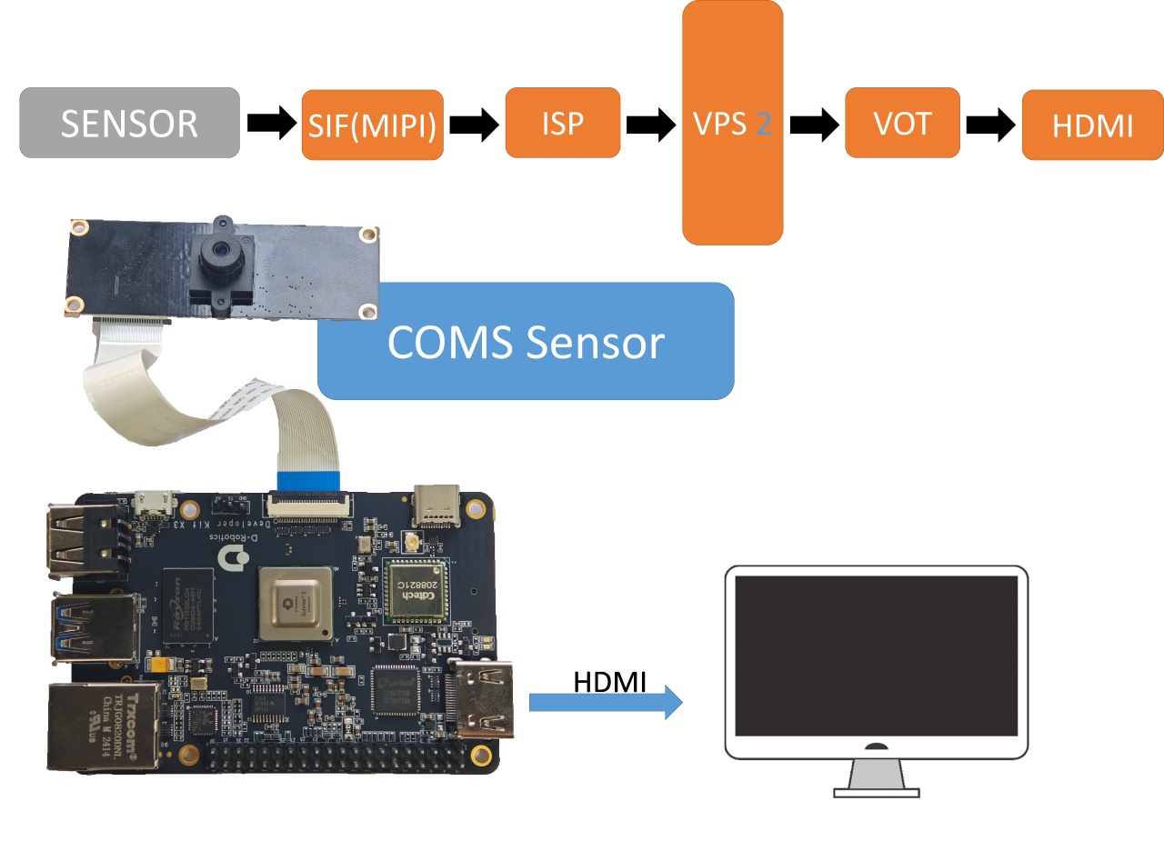
The vio2display example implements the functionality of capturing images from a MIPI camera and outputting them via the HDMI interface for preview on a display. The flowchart of the example is shown below:
-
Environment Setup:
- With the development board powered off, connect the
MIPIcamera to the development board. Refer to the MIPI camera connection tutorial for the connection method. - Connect the development board to the display via an HDMI cable.
- Power on the development board and log in through the command line.
- With the development board powered off, connect the
-
Running Instructions: The example code is provided in source code form and needs to be compiled and run using the
makecommand. Follow these steps:sunrise@ubuntu:~$ cd /app/cdev_demo/vio2display
sunrise@ubuntu:/app/cdev_demo/vio2display$ sudo make
sunrise@ubuntu:/app/cdev_demo/vio2display$ sudo ./vio2display -w 1920 -h 1080Parameters:
- -w: sensor output width
- -h: sensor output height
-
Expected Results: After the program runs successfully, the development board will output the real-time image captured by the
MIPIcamera to the display. The running log is as follows:sunrise@ubuntu:/tmp/nfs/sp_cdev/cdev_demo/vio2display$ ./vio2display -w 1920 -h 1080
disp_w=1920, disp_h=1080
2023/03/28 02:08:03.359 !INFO [x3_cam_init_param][0099]Enable mipi host0 mclk
2023/03/28 02:08:03.359 !INFO [x3_cam_init_param][0099]Enable mipi host1 mclk
Camera: gpio_num=114, active=low, i2c_bus=3, mipi_host=0
Camera: gpio_num=114, active=low, i2c_bus=1, mipi_host=1
Camera: gpio_num=114, active=low, i2c_bus=0, mipi_host=2
Camera 0:
enable: 1
i2c_bus: 3
mipi_host: 0
Camera 1:
enable: 1
i2c_bus: 1
mipi_host: 1
Camera 2:
enable: 1
i2c_bus: 0
mipi_host: 2
cmd=i2ctransfer -y -f 3 w2@0x10 0x0 0x0 r1 2>&1, result=0x02
Found sensor:imx219 on i2c bus 3, use mipi host 0
Setting VPS channel-2: src_w:1920, src_h:1080; dst_w:1920, dst_h:1080;
Setting VPS channel-1: src_w:1920, src_h:1080; dst_w:1920, dst_h:1080;
sp_open_camera success!
libiar: hb_disp_set_timing done!
Press 'q' to Exit !
Camera Image Local Save (RDK X3)
The vio_capture example in this document realizes the function of capturing images from a MIPI camera and saving the images locally in both RAW and YUV formats. The flowchart of the example is as follows:
-
Preparation:
- Connect the
MIPIcamera to the development board while the development board is powered off. For the connection method, see MIPI Camera Connection Guide. - Connect the development board and the monitor with an HDMI cable.
- Power on the development board and log in through the command line.
- Connect the
-
Running the Example: The example code is provided in source code form. After compiling the code using the
makecommand, run the example as follows:sunrise@ubuntu:~$ cd /app/cdev_demo/vio_capture/
sunrise@ubuntu:/app/cdev_demo/vio_capture$ sudo make
sunrise@ubuntu:/app/cdev_demo/vio_capture$ sudo ./capture -b 12 -c 10 -h 1080 -w 1920Parameter description:
- -b: bit number of the RAW image, IMX477: 12, others: 10
- -c: number of images to be saved
- -w: width of the saved images
- -h: height of the saved images
-
Expected Result: After the program runs correctly, the specified number of image files is saved in the current directory. The
RAWformat is named asraw_*.raw, and theYUVformat is named asyuv_*.yuv. The running log is as follows:sunrise@ubuntu:/app/cdev_demo/vio_capture$ sudo ./capture -b 12 -c 10 -h 1080 -w 1920
Setting VPS channel-2: src_w:1920, src_h:1080; dst_w:1920, dst_h:1080;
Setting VPS channel-1: src_w:1920, src_h:1080; dst_w:1920, dst_h:1080;
jiale:start streaming...
capture time :0
capture time :1
capture time :2
capture time :3
capture time :4
capture time :5
capture time :6
capture time :7
capture time :8
capture time :9
sensor_name imx477, setting_size = 1
[ 701.213210]hb_isp_algo_stop@main_user.c:389 GENERIC(ERR) :g_mutex destroy.
Camera Image Local Saving (RDK X5)
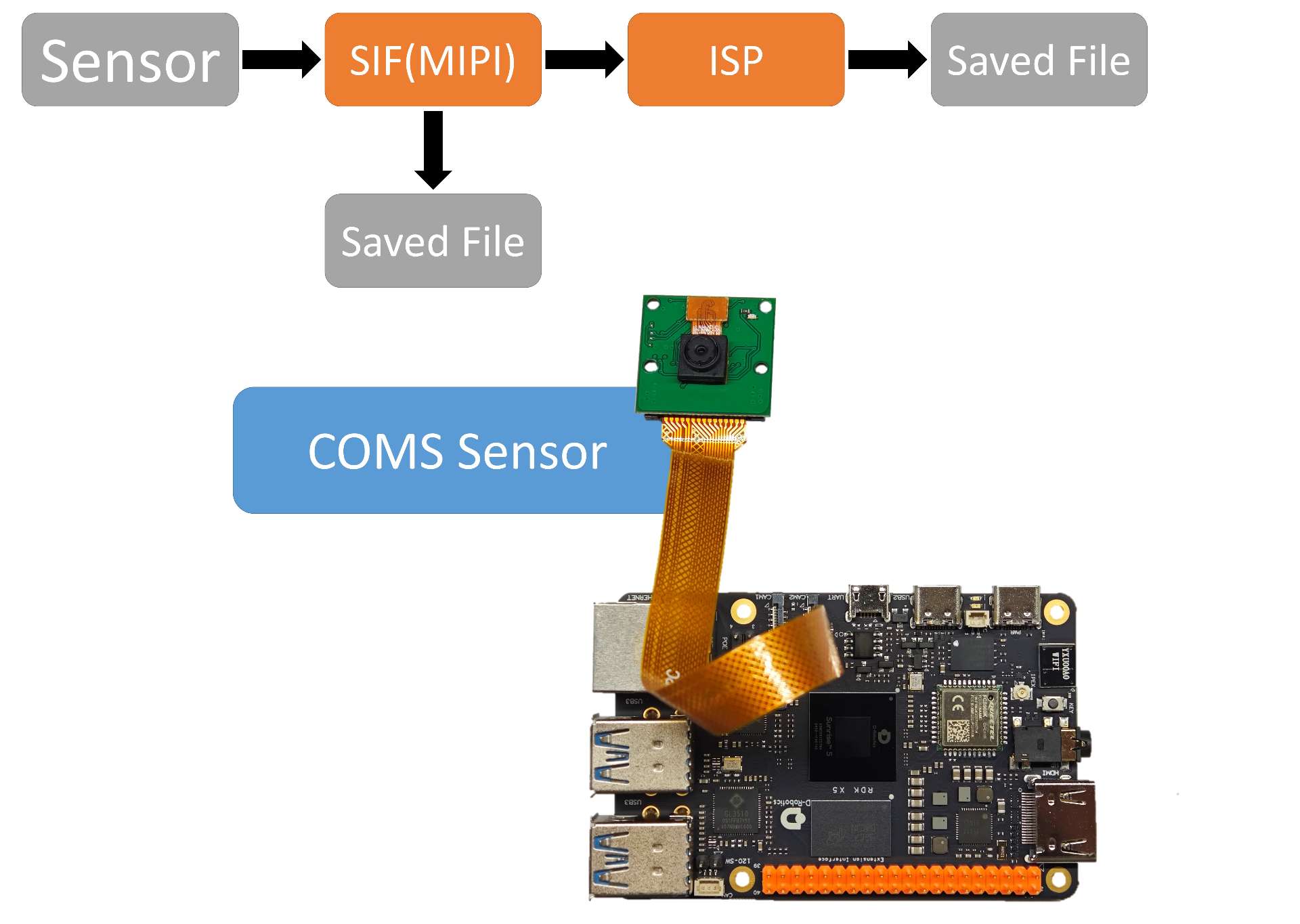
The vio_capture example demonstrates how to capture images from a MIPI camera and save them locally in both RAW and YUV formats. The workflow diagram is shown below:
- Environment Setup
- Power off the development board, connect the
MIPIcamera to the board. Refer to Hardware Introduction - MIPI Interface for detailed connection instructions. - Connect the development board to a monitor using an HDMI cable.
- Power on the board and log in via the command line.
- Execution Steps
The example code is provided as source code and requires compilation with the
makecommand. Follow the steps below to run the program:
sunrise@ubuntu:~$ cd /app/cdev_demo/vio_capture/
sunrise@ubuntu:/app/cdev_demo/vio_capture$ sudo make
sunrise@ubuntu:/app/cdev_demo/vio_capture$ sudo ./capture -b 16 -c 10 -h 1080 -w 1920
Parameter Explanation:
-
-b: RAW image bit depth. Set to 16 for IMX219 / IMX477 / OV5647. Rarely, some Camera Sensors require 8.
-
-c: Number of images to save.
-
-w: Width of the saved images.
-
-h: Height of the saved images.
-
Expected Output When the program runs successfully, the specified number of image files will be saved in the current directory:
-
RAWformat images will be named asraw_*.raw. -
YUVformat images will be named asyuv_*.yuv.
The following is an example of the runtime log:
sunrise@ubuntu:/app/cdev_demo/vio_capture$ sudo ./capture -b 16 -c 10 -h 1080 -w 1920
[INFO] board_id is 301, not need skip sci1.
Searching camera sensor on device: /proc/device-tree/soc/cam/vcon@0 i2c bus: 6 mipi rx phy: 0
INFO: Found sensor name:ov5647 on mipi rx csi 0, i2c addr 0x36, config_file:linear_1920x1080_raw10_30fps_2lane.c
2000/01/01 08:18:54.877 !INFO [CamInitParam][0139]Setting VSE channel-0: input_width:1920, input_height:1080,  dst_w:1920, dst_h:1080
2000/01/01 08:18:54.877 !INFO [CamInitParam][0139]Setting VSE channel-1: input_width:1920, input_height:1080, dst_w:1920, dst_h:1080
... omitted ...
capture time :0
temp_ptr.data_size[0]:4147200
capture time :1
temp_ptr.data_size[0]:4147200
capture time :2
temp_ptr.data_size[0]:4147200
... omitted ...
capture time :8
temp_ptr.data_size[0]:4147200
capture time :9
temp_ptr.data_size[0]:4147200
ov5647 sensor stop
Camera Image Local Saving (RDK Ultra)
This vio_capture example demonstrates the image capture of a MIPI camera and provides the functionality to save the captured images locally in both RAW and YUV formats (mutually exclusive). The flowchart of the example is shown below:
-
Preparation:
- With the development board powered off, connect the
MIPIcamera to the board. Refer to the MIPI Camera Connection Tutorial for the connection method. - Connect the development board to a display monitor via an HDMI cable.
- Power on the development board and log in via the command line interface.
- If you need to obtain raw data, please follow the steps below:
- Edit the configuration file of the corresponding camera. Taking
IMX219as an example, edit/etc/camera_configs/Ultra/imx219/1080/vpm.json. - Modify the
isp_dma_output_formatfield to4and save the changes.
- Edit the configuration file of the corresponding camera. Taking
- If you need to obtain images in the
NV12format, please follow the steps below:- Edit the configuration file of the corresponding camera. Taking
IMX219as an example, edit/etc/camera_configs/Ultra/imx219/1080/vpm.json. - Modify the
isp_stream_output_formatfield to0; modify theisp_dma_output_formatfield to9; modify thepym_modefield to0; and save the changes.
- Edit the configuration file of the corresponding camera. Taking
- With the development board powered off, connect the
-
Execution: The example code is provided in source code form and needs to be compiled and run using the
makecommand. The steps are as follows:sunrise@ubuntu:~$ cd /app/cdev_demo/vio_capture/
sunrise@ubuntu:/app/cdev_demo/vio_capture$ sudo make
sunrise@ubuntu:/app/cdev_demo/vio_capture$ sudo ./capture -b 12 -c 10 -h 1080 -w 1920 -m 0Parameter explanation:
- -b: Bit number of the RAW image, currently set to 12
- -c: Number of images to save
- -w: Width of the images to save
- -h: Height of the images to save
- -m: Type of the images to save, 0: YUV, 1: RAW
-
Expected Result: After the program runs correctly, the specified number of image files will be saved in the current directory. The
RAWformat is named asraw_*.raw, and theYUVformat is named asyuv_*.yuv. The running log is as follows:root@ubuntu:/app/cdev_demo/media_cdev/vio_capture# sudo ./capture -b 12 -c 10 -h 1080 -w 1920 -m 0
Camera: gpio_num=432, active=low, i2c_bus=6, mipi_host=3
Camera: gpio_num=293, active=low, i2c_bus=5, mipi_host=1
Camera: gpio_num=290, active=low, i2c_bus=4, mipi_host=2
Camera: gpio_num=289, active=low, i2c_bus=2, mipi_host=0
cmd=i2ctransfer -y -f 6 w2@0x10 0x0 0x0 r1 2>&1, result=0x02
capture time :0
capture time :1
capture time :2
capture time :3
capture time :4
capture time :5
capture time :6
capture time :7
capture time :8
capture time :9
sensor_name imx219, setting_size = 1
Camera Image Capture and Encoding
This example vio2encoder implements the MIPI camera image capture function and saves the encoded image locally for previewing on a monitor. The flowchart of the example is as follows:
-
Preparation:
- With the development board powered off, connect the MIPI camera to the development board. Refer to the MIPI camera connection tutorial for the connection method.
- Connect the development board to the monitor using an HDMI cable.
- Power on the development board and log in through the command line.
-
Execution: Execute the program according to the following command. The example code is provided in source code form and needs to be compiled using the
makecommand before execution. The steps are as follows:sunrise@ubuntu:~$ cd /app/cdev_demo/vio2encoder
sunrise@ubuntu:/app/cdev_demo/vio2encoder$ sudo make
sunrise@ubuntu:/app/cdev_demo/vio2encoder$ sudo ./vio2encoder -w 1920 -h 1080 --iwidth 1920 --iheight 1080 -o test.h264Parameter explanation:
- -w: Video encoding width
- -h: Video encoding height
- --iwidth: Sensor output width
- --iheight: Sensor output height
- -o: Encoding output path
-
Expected Result: After the program runs successfully, a video file named
stream.h264will be generated in the current directory. The log during the run is as follows:sunrise@ubuntu:/tmp/nfs/sp_cdev/cdev_demo/vio2encoder$ sudo ./vio2encoder -w 1920 -h 1080 --iwidth 1920 --iheight 1080 -o test.h264
2023/03/28 02:27:32.560 !INFO [x3_cam_init_param][0099]Enable mipi host0 mclk
2023/03/28 02:27:32.561 !INFO [x3_cam_init_param][0099]Enable mipi host1 mclk
Camera: gpio_num=114, active=low, i2c_bus=3, mipi_host=0
Camera: gpio_num=114, active=low, i2c_bus=1, mipi_host=1
Camera: gpio_num=114, active=low, i2c_bus=0, mipi_host=2
Camera 0:
enable: 1
i2c_bus: 3
mipi_host: 0
Camera 1:
enable: 1
i2c_bus: 1mipi_host: 1
Camera 2:
enable: 1
i2c_bus: 0
mipi_host: 2
cmd=i2ctransfer -y -f 3 w2@0x10 0x0 0x0 r1 2>&1, result=0x02
Found sensor:imx219 on i2c bus 3, use mipi host 0
Setting VPS channel-2: src_w:1920, src_h:1080; dst_w:1920, dst_h:1080;
Setting VPS channel-1: src_w:1920, src_h:1080; dst_w:1920, dst_h:1080;
sp_open_camera success!
sp_start_encode success!
sp_module_bind(vio -> encoder) success!
Camera Image Capture and Encoding (RDK X5)
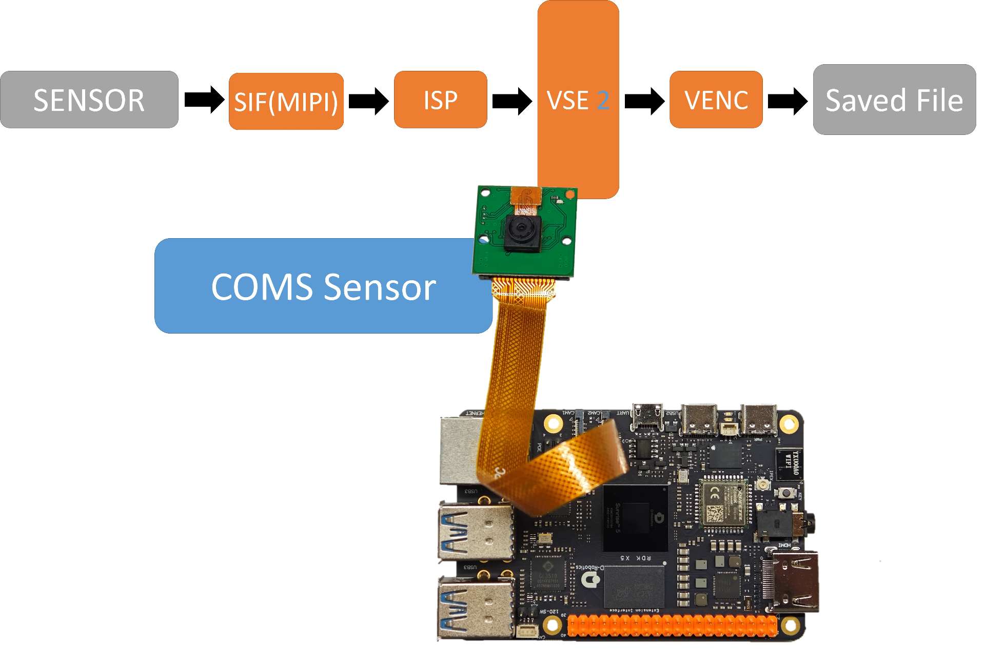
The vio2encoder example demonstrates the functionality of capturing images from a MIPI camera, encoding them, saving them locally, and previewing the footage on a display. The workflow diagram is shown below:
- Environment Setup
- Power off the development board and connect the
MIPIcamera. Refer to Hardware Introduction - MIPI Interface for connection details. - Connect the development board to a monitor using an HDMI cable.
- Power on the board and log in via the command line.
- Execution Steps
Execute the program using the following steps. The example code is provided as source code and requires compilation with the
makecommand:
sunrise@ubuntu:~$ cd /app/cdev_demo/vio2encoder
sunrise@ubuntu:/app/cdev_demo/vio2encoder$ sudo make
sunrise@ubuntu:/app/cdev_demo/vio2encoder$ sudo ./vio2encoder -w 1920 -h 1080 --iwidth 1920 --iheight 1080 -o stream.h264
Parameter Explanation:
- -w: Encoded video width.
- -h: Encoded video height.
- --iwidth: Sensor output width.
- --iheight: Sensor output height.
- -o: Output path for the encoded file.
- Expected Output
When the program runs successfully, a video file named
stream.h264will be created in the current directory. Below is an example of the runtime log:
sunrise@ubuntu:/tmp/nfs/sp_cdev/cdev_demo/vio2encoder$ sudo ./vio2encoder -w 1920 -h 1080 --iwidth 1920 --iheight 1080 -o stream.h264
[INFO] board_id is 301, not need skip sci1.
Searching camera sensor on device: /proc/device-tree/soc/cam/vcon@0 i2c bus: 6 mipi rx phy: 0
INFO: Found sensor name:ov5647 on mipi rx csi 0, i2c addr 0x36, config_file:linear_1920x1080_raw10_30fps_2lane.c
2000/01/01 18:43:43.374 !INFO [CamInitParam][0139]Setting VSE channel-0: input_width:1920, input_height:1080, dst_w:1920, dst_h:1080
2000/01/01 18:43:43.374 !INFO [CamInitParam][0139]Setting VSE channel-1: input_width:1920, input_height:1080, dst_w:1920, dst_h:1080
... omitted ...
sp_open_camera success!
2000/01/01 18:43:44.166 !INFO [vp_encode_config_param][0405]codec type is h264: frame size:3110912  frame rate: 30
sp_start_encode success!
sp_module_bind(vio -> encoder) success!
Video file decoding and displaying
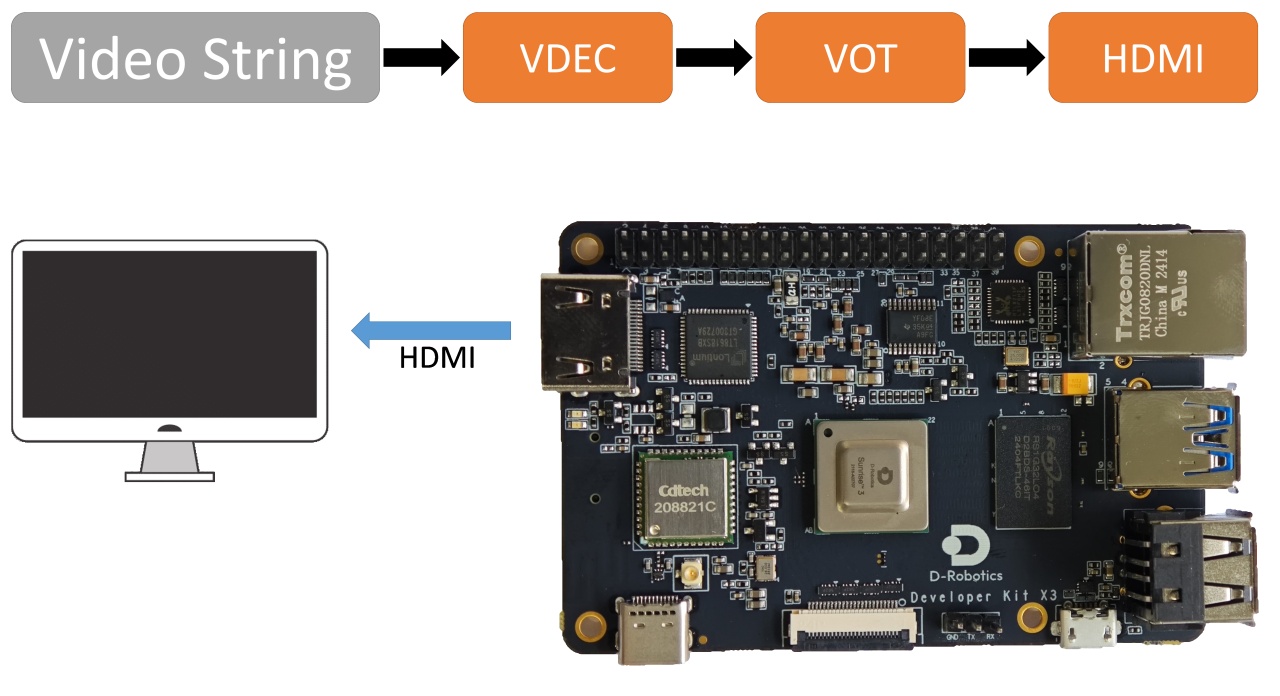
This example decoder2display implements video file decoding and outputs it through the HDMI interface for previewing on a monitor. The flowchart of the example is as follows:
-
Preparation:
- Connect the development board to the monitor using an HDMI cable.
- Power on the development board and log in via the command line.
- Prepare the video file
stream.h264as the input.
-
Running: The sample code is provided in source code form. You need to use the
makecommand to compile and then run. The steps are as follows:sunrise@ubuntu:~$ cd /app/cdev_demo/decode2display
sunrise@ubuntu:/app/cdev_demo/decode2display$ sudo make
sunrise@ubuntu:/app/cdev_demo/decode2display$ sudo ./decoder2display -w 1920 -h 1080 -i stream.h264Parameter description:
- -h: height of the video file
- -w: width of the video file
- -i: the path of the video file
-
Expected result: After the program is running correctly, the video image will be output through the
HDMIinterface of the development board, and the user can preview the video image on the monitor. The running log is as follows:sunrise@ubuntu:/app/cdev_demo/decode2display$ sudo ./decoder2display -w 1920 -h 1080 -i stream.h264
disp_w=1024, disp_h=600
[x3_av_open_stream]:[380]:probesize: 5000000
sp_start_decode success!
libiar: hb_disp_set_timing done!
sp_start_display success!
sp_open_vps success!
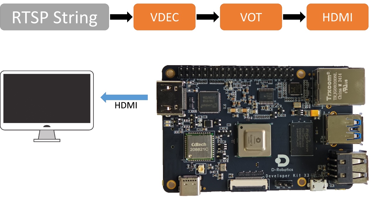
RTSP Streaming Decode
This example rtsp2display implements the function of pulling rtsp stream, decoding it, and outputting the video image through HDMI, allowing users to preview the image on a monitor. The flowchart of the example is as follows:
-
Environment Preparation:
- Connect the development board to the monitor using an HDMI cable.
- Power on the development board and login via the command line.
- Prepare the
rtspstream as the input source.
-
Running Method: The example code is provided in source code form and needs to be compiled and run using the
makecommand. The steps are as follows:sunrise@ubuntu:~$ cd /app/cdev_demo/rtsp2display
sunrise@ubuntu:/app/cdev_demo/rtsp2display$ sudo make #There may be some warning messages, which can be ignored.
sunrise@ubuntu:/app/cdev_demo/decode2display$ sudo ./rtsp2display -i rtsp://admin:admin123@10.96.32.170:554/0 -t tcpParameter configuration:
- -i: URL address of the stream
- -t: Transport type, TCP/UDP optional
-
Expected Result: After the program runs correctly, the video image will be output through the
HDMIinterface of the development board, and users can preview the video image on the monitor. The running log is as follows:sunrise@ubuntu:/app/cdev_demo/rtsp2display$ sudo ./rtsp2display -i rtsp://admin:admin123@10.96.32.170:554/0 -t tcp
avformat_open_input ok!
avformat_find_stream_info ok!
Input #0, rtsp, from 'rtsp://admin:admin123@10.96.32.170:554/0':
Metadata:
title : h264.mp4
Duration: N/A, start: 0.040000, bitrate: N/A
Stream #0:0: Video: h264 (Main), yuvj420p(pc, bt709, progressive), 1920x1080, 25 tbr, 90k tbn, 180k tbc
Stream #0:1: Audio: pcm_mulaw, 8000 Hz, 1 channels, s16, 64 kb/s
Input #1, rtsp, from 'rtsp://admin:admin123@10.96.32.170:554/0':
Metadata:
title : h264.mp4
Duration: N/A, start: 0.040000, bitrate: N/A
Stream #1:0: Video: h264 (Main), yuvj420p(pc, bt709, progressive), 1920x1080, 25 tbr, 90k tbn, 180k tbc
Stream #1:1: Audio: pcm_mulaw, 8000 Hz, 1 channels, s16, 64 kb/s
av_dump_format ok!
rtsp_w:1920,rtsp_h:1080
display_w:1024,dispaly_h:600
libiar: hb_disp_set_timing done!
sp_open_vps success! -
Notes:
- When using UDP protocol to transmit the stream, there may be screen flicker due to network packet loss. In this case, switching to TCP protocol can solve the problem.
VPS Scaling Example
This example implements video scaling functionality based on the video processing module VPS. Users can preview the image through a monitor.
-
Environment Preparation:
- Connect the development board and the monitor via HDMI cable
- Power on the development board and log in through the command line
- Prepare the image (NV12) and video file (H264) as inputs
-
How to Run: The sample code is provided in source code format and needs to be compiled and run using the
makecommand. The steps are as follows:sunrise@ubuntu:~$ cd /app/cdev_demo/vps
sunrise@ubuntu:/app/cdev_demo/vps$ sudo make
sunrise@ubuntu:/app/cdev_demo/vps$ sudo ./vps -m 1 -i stream.h264 -o output.yuv --iheight 1080 --iwidth 1920 --oheight 720 --owidth 1280Parameter Configuration:
- -i: Path of the file to be operated
- -iheight: Input height
- -iwidth: Input width
- -m: Input mode, 1: video stream; 2: NV12 image
- -o: Output path
- -oheight: Output height
- -width: Output width
- -skip: (optional) For video stream input, skip the number of frames at the beginning
-
Expected Result: After the program runs correctly, the processed image file
output.yuvwill be saved in the current directory. The running log is as follows:sunrise@ubuntu:/app/cdev_demo/vps$ sudo ./vps -m 1 -i stream.h264 -o output.yuv --iheight 1080 --iwidth 1920 --oheight 720 --ow
idth 1280
[x3_av_open_stream]:[380]:probesize: 5000000
hb_vp_deinit success
Object Detection Algorithm - FCOS
This example uses the FCOS model to implement the object detection algorithm for local video streams. Users can preview the detection results through a monitor.
-
Environment Preparation:
- Connect the development board and the monitor via HDMI cable
- Power on the development board and log in through the command line
- Prepare the video file (H264) as the input
-
How to Run: The sample code is provided in source code format and needs to be compiled and run using the
makecommand. The steps are as follows:sunrise@ubuntu:~$ cd /app/cdev_demo/bpu/src
sunrise@ubuntu:/app/cdev_demo/bpu/src$ sudo makesunrise@ubuntu:/app/cdev_demo/bpu/src$ cd bin
sunrise@ubuntu:/app/cdev_demo/bpu/src/bin$ sudo ./sample -f /app/model/basic/fcos_512x512_nv12.bin -m 1 -i 1080p_.h264 -w 1920 -h 1080
Parameter Configuration:
- -f: Model file path
- -h: Height of the input video
- -w: Width of the input video
- -i: Path of the input video
- -m: Model type, default is 1
Expected Output:
After the program runs successfully, the video and the rendered image after algorithm detection will be output through the HDMI interface for user preview on a display. The running log is as follows:
sunrise@ubuntu:/app/cdev_demo/bpu/src/bin$ sudo ./sample -f /app/model/basic/fcos_512x512_nv12.bin -m 1 -i 1080p_.h264 -w 1920 -h 1080
[BPU_PLAT]BPU Platform Version(1.3.1)!
[HBRT] set log level as 0. version = 3.14.5
[DNN] Runtime version = 1.9.7_(3.14.5 HBRT)
Model info:
model_name: fcos_512x512_nv12Input count: 1input[0]: tensorLayout: 2 tensorType: 1 validShape:(1, 3, 512, 512, ), alignedShape:(1, 3, 512, 512, )
Output count: 15Output[0]: tensorLayout: 0 tensorType: 13 validShape:(1, 64, 64, 80, ), alignedShape:(1, 64, 64, 80, )
Output[1]: tensorLayout: 0 tensorType: 13 validShape:(1, 32, 32, 80, ), alignedShape:(1, 32, 32, 80, )
Output[2]: tensorLayout: 0 tensorType: 13 validShape:(1, 16, 16, 80, ), alignedShape:(1, 16, 16, 80, )
Output[3]: tensorLayout: 0 tensorType: 13 validShape:(1, 8, 8, 80, ), alignedShape:(1, 8, 8, 80, )
Output[4]: tensorLayout: 0 tensorType: 13 validShape:(1, 4, 4, 80, ), alignedShape:(1, 4, 4, 80, )
Output[5]: tensorLayout: 0 tensorType: 13 validShape:(1, 64, 64, 4, ), alignedShape:(1, 64, 64, 4, )
Output[6]: tensorLayout: 0 tensorType: 13 validShape:(1, 32, 32, 4, ), alignedShape:(1, 32, 32, 4, )
Output[7]: tensorLayout: 0 tensorType: 13 validShape:(1, 16, 16, 4, ), alignedShape:(1, 16, 16, 4, )
Output[8]: tensorLayout: 0 tensorType: 13 validShape:(1, 8, 8, 4, ), alignedShape:(1, 8, 8, 4, )
Output[9]: tensorLayout: 0 tensorType: 13 validShape:(1, 4, 4, 4, ), alignedShape:(1, 4, 4, 4, )
Output[10]: tensorLayout: 0 tensorType: 13 validShape:(1, 64, 64, 1, ), alignedShape:(1, 64, 64, 1, )
Output[11]: tensorLayout: 0 tensorType: 13 validShape:(1, 32, 32, 1, ), alignedShape:(1, 32, 32, 1, )
Output[12]: tensorLayout: 0 tensorType: 13 validShape:(1, 16, 16, 1, ), alignedShape:(1, 16, 16, 1, )
Output[13]: tensorLayout: 0 tensorType: 13 validShape:(1, 8, 8, 1, ), alignedShape:(1, 8, 8, 1, )
Output[14]: tensorLayout: 0 tensorType: 13 validShape:(1, 4, 4, 1, ), alignedShape:(1, 4, 4, 1, )
libiar: hb_disp_set_timing done!
dispaly init ret = 0
vps open ret = 0
module bind vps & display ret = 0
display start ret = 0
[x3_av_open_stream]:[380]:probesize: 5000000
decode start ret = 0
module bind decoder & vps ret = 0
[ERROR]["vdec"][video/src/vdec_group.c:348] [8870.450264]vdec_channel_bump_thread[348]: VDEC_MODULE module try again

[draw_rect]:[137]:========point is 0,return========
fps:55.555556,processing time:18
Object Detection Algorithm - YOLOv5
This example is based on the YOLOv5 model and implements the camera object detection algorithm, allowing users to preview the detection results on the monitor.
-
Environment Setup:
- With the development board powered off, connect the
MIPIcamera to the development board following the instructions in the MIPI Camera Connection Tutorial. - Connect the development board to the monitor using an HDMI cable.
- Power on the development board and log in via the command line.
- With the development board powered off, connect the
-
Execution: The sample code is provided in source code form, and it needs to be compiled using the
makecommand before execution. The steps are as follows:sunrise@ubuntu:~$ cd /app/cdev_demo/bpu/src
sunrise@ubuntu:/app/cdev_demo/bpu/src$ sudo make
sunrise@ubuntu:/app/cdev_demo/bpu/src$ cd bin
sunrise@ubuntu:/app/cdev_demo/bpu/src/bin$ sudo ./sample -f /app/model/basic/yolov5_672x672_nv12.bin -m 0Parameter Configuration:
- -f: path to the model
- -m: model type, default is 0
-
Expected Result: After the program runs correctly, the video output via the
HDMIinterface will display the rendered image with the algorithm detection. Users can preview it on the monitor. The following is the log during execution:sunrise@ubuntu:/app/cdev_demo/bpu/src/bin$ sudo ./sample -f /app/model/basic/yolov5_672x672_nv12.bin -m 0
[BPU_PLAT]BPU Platform Version(1.3.1)!
[HBRT] set log level as 0. version = 3.14.5
[DNN] Runtime version = 1.9.7_(3.14.5 HBRT)
Model info:
model_name: yolov5_672x672_nv12Input count: 1input[0]: tensorLayout: 2 tensorType: 1 validShape:(1, 3, 672, 672, ), alignedShape:(1, 3, 672, 672, )
Output count: 3Output[0]: tensorLayout: 0 tensorType: 13 validShape:(1, 84, 84, 255, ), alignedShape:(1, 84, 84, 255, )
Output[1]: tensorLayout: 0 tensorType: 13 validShape:(1, 42, 42, 255, ), alignedShape:(1, 42, 42, 255, )
Output[2]: tensorLayout: 0 tensorType: 13 validShape:(1, 21, 21, 255, ), alignedShape:(1, 21, 21, 255, )
Setting VPS channel-1: src_w:1920, src_h:1080; dst_w:672, dst_h:672;
Setting VPS channel-3: src_w:1920, src_h:1080; dst_w:1024, dst_h:600;
Setting VPS channel-2: src_w:1920, src_h:1080; dst_w:1920, dst_h:1080;
start linear mode, sensor_name f37, setting_size = 3
libiar: hb_disp_set_timing done!
yolov5_do_post fps:11.627907,processing time :86