Lesson 12: RDK X5 40-pin UART and I2C
This lesson uses UART1 and I2C5 on the RDK X5 40-pin header. You will verify UART with a loopback test and drive an SSD1306 OLED over I2C.
Hardware: RDK X5
Code and full lesson: Lesson 12 directory
Learning objectives
After this lesson, you will be able to:
- Explain the roles of UART TX, RX, and GND
- Locate UART1 with BOARD physical pin numbers
- Explain baud rate and the 8N1 format
- Run the built-in loopback sample
- Send and receive bytes with Python and pyserial
- Discover an I2C device with
i2cdetect - Display text and a live clock on an SSD1306 OLED
UART basics
UART transfers data asynchronously. TX sends data and RX receives it. Since the two devices do not share a clock signal, both sides must use the same baud rate, data bits, parity, stop bits, and flow-control settings.
This lesson uses 115200 baud, 8N1, and no flow control.
| Parameter | Value |
|---|---|
| Baud rate | 115200 |
| Data bits | 8 |
| Parity | None |
| Stop bits | 1 |
| Flow control | None |
For a real peripheral, connect RDK TX to peripheral RX, RDK RX to peripheral TX, and connect both grounds.
RDK X5 UART1 pins
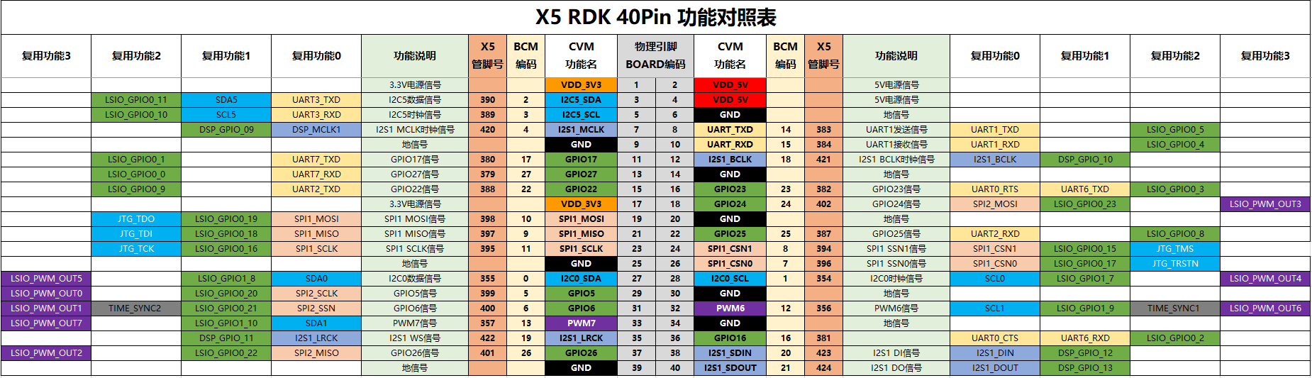
RDK X5 enables UART1 on physical pins 8 and 10 by default. The logic level is 3.3 V.
| BOARD pin | Signal | Purpose |
|---|---|---|
| Pin 8 | UART1_TXD | RDK transmit |
| Pin 10 | UART1_RXD | RDK receive |
| Pin 6 | GND | Common ground |
Power off the board before wiring. Do not connect RS-232 voltage levels or a 5 V UART signal directly to the 40-pin header.
Check the serial device
List the enabled serial devices:
The RDK X5 40-pin UART1 normally appears as /dev/ttyS1. /dev/ttyS0 is the system debug console and should not be used for this lesson.
UART1 is enabled by default. If pins 8 and 10 do not work as UART, run sudo srpi-config, open 3 Interface Options, select I3 Peripheral bus config, and confirm that the serial interface is okay. Reboot after changing the configuration.
Check pyserial:
If Python reports ModuleNotFoundError, install it with:
Run the built-in loopback test
Power off the board and connect BOARD pin 8 directly to BOARD pin 10 with one jumper wire. Do not connect a 3.3 V or 5 V power pin for this test.
Run the built-in sample:
Enter /dev/ttyS1 for the device and 115200 for the baud rate. A working loopback prints matching transmitted and received data:
Run the course demo
The course demo uses fixed settings and does not require command-line arguments.
git clone https://github.com/D-Robotics/rdk-course-demos.git
cd rdk-course-demos/01_beginner/12_40pin_uart_i2c/code
python3 uart_loopback.py
The program sends AA55 once per second, reads four bytes, and closes the serial device when you press Ctrl+C.
Python serial API
| API | Purpose |
|---|---|
serial.Serial("/dev/ttyS1", 115200, timeout=1) |
Open UART1 and configure its baud rate and timeout |
ser.write(data) |
Write bytes |
ser.read(size) |
Read a fixed number of bytes |
ser.readline() |
Read one line |
ser.close() |
Close and release the serial device |
write() expects bytes. Use encode() before sending text and decode() after receiving bytes.
Connect a real UART peripheral
| RDK X5 | Peripheral |
|---|---|
| BOARD pin 8, UART1_TXD | RX |
| BOARD pin 10, UART1_RXD | TX |
| BOARD pin 6, GND | GND |
Check the peripheral manual before powering it from the board. The signal level must be compatible with 3.3 V TTL UART.
I2C OLED experiment
I2C uses SDA for data and SCL for the clock. On RDK X5, physical pins 3 and 5 provide I2C5 through /dev/i2c-5.
| OLED pin | RDK X5 BOARD pin |
|---|---|
| VCC | Pin 1, 3.3 V |
| GND | Pin 39 |
| SDA | Pin 3, I2C5_SDA |
| SCL | Pin 5, I2C5_SCL |
Scan the bus before running Python:
When address 3c appears, run the course demo:
cd rdk-course-demos/01_beginner/12_40pin_uart_i2c/code
python3 -m pip install luma.oled
python3 i2c_display.py
The core OLED display code is shown below:
#!/usr/bin/env python3
import time

from luma.core.interface.serial import i2c
from luma.oled.device import ssd1306
from PIL import Image, ImageDraw, ImageFont

# Initialize the OLED on I2C5 at address 0x3C.
serial = i2c(port=5, address=0x3C)
device = ssd1306(serial)
font = ImageFont.load_default()

while True:
    image = Image.new("1", (128, 64))
    draw = ImageDraw.Draw(image)

    draw.text((0, 0), "RDK X5", font=font, fill=255)
    draw.text((0, 18), "I2C OLED Demo", font=font, fill=255)
    draw.text((0, 36), time.strftime("%H:%M:%S"), font=font, fill=255)

    device.display(image)
    time.sleep(1)
Use python3 i2c_display.py --address 0x3D if the scan reports 3d. If the display stays blank, verify the bus number, address, and whether the controller is SSD1306 or SH1106.
Troubleshooting
| Symptom | Check |
|---|---|
/dev/ttyS1 is missing |
Check the serial interface in srpi-config, then reboot |
Permission denied |
Check device permissions or run the test with sudo python3 |
| No received data | Check the loopback wire or verify that TX and RX are crossed |
| Garbled text | Make both sides use the same baud rate, data bits, parity, and stop bits |
| Unstable data | Connect common ground and verify 3.3 V TTL levels |
| I2C device is missing | Check SDA/SCL, power, pull-ups, bus number, and pin mux settings |
| OLED stays blank | Verify 0x3C/0x3D and the SSD1306/SH1106 controller type |
Summary
- UART1 uses BOARD pins 8 and 10 on RDK X5
- The interface uses 3.3 V TTL logic
- This lesson uses 115200 baud, 8N1, and no flow control
- UART1 normally appears as
/dev/ttyS1; do not use the/dev/ttyS0debug console - Verify the interface with a loopback test before connecting a real peripheral
- I2C5 uses BOARD pins 3 and 5 and appears as
/dev/i2c-5 - Scan the I2C address before running the OLED program