1.1.2 Hardware Introduction
For related download resources, please refer to: Download Resources Summary
Includes specification sheets, schematics, mechanical drawings, 3D drawings, reference design materials, and other complete hardware documentation.
Interface Overview
RDK X5 provides various functional interfaces, including Ethernet, USB, camera, LCD, HDMI, CAN FD, and 40-pin GPIO, enabling users to develop and test applications such as multimedia processing and deep learning algorithms. The layout of the development board's interfaces is shown below:
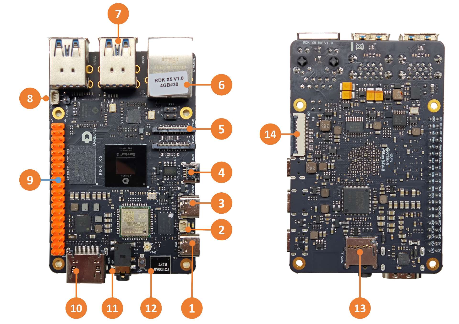
| No. | Function | No. | Function | No. | Function |
|---|---|---|---|---|---|
| 1 | Power Interface (USB Type C) | 2 | RTC Battery Interface (The pin closer to PWR is B+, the other pin is GND) | 3 | QuickLink Port (USB Type C) |
| 4 | Debug Serial Port (Micro USB) | 5 | Dual MIPI Camera Ports | 6 | Gigabit Ethernet Port with PoE |
| 7 | 4 USB 3.0 Type A Ports | 8 | High-Speed CAN FD Interface | 9 | 40-pin GPIO Interface |
| 10 | HDMI Display Interface | 11 | Multi-standard Headphone Jack | 12 | Onboard Wi-Fi Antenna |
| 13 | TF Card Interface (Bottom) | 14 | LCD Display Interface (MIPI DSI) |
RDK X5 Module is a small form-factor version of the RDK X5 development board, featuring a smaller form factor and reduced number of interfaces. The layout of the module's interfaces is shown below:
Direct output interfaces include:
- Two 22-pin camera interfaces (integrated MIPI CSI, LPWM & MCLK, I²C, GPIO)
- One HDMI interface
- One RJ45 Ethernet interface
- One LCD interface (integrated MIPI DSI and I²C)
- 40-pin expansion interface (including GPIO, I²C, SPI, I²S, PWM)
- Multiple functional control interfaces
Interfaces output through IO carrier board with peripheral components include:
- CAN bus interface (using TCAN4550 chip, SPI-to-CAN)
- Headphone audio interface (based on ES8326B, supporting I²S to audio DAC & ADC)
- Four USB 3.0 ports (expanded via GL3510 USB hub)
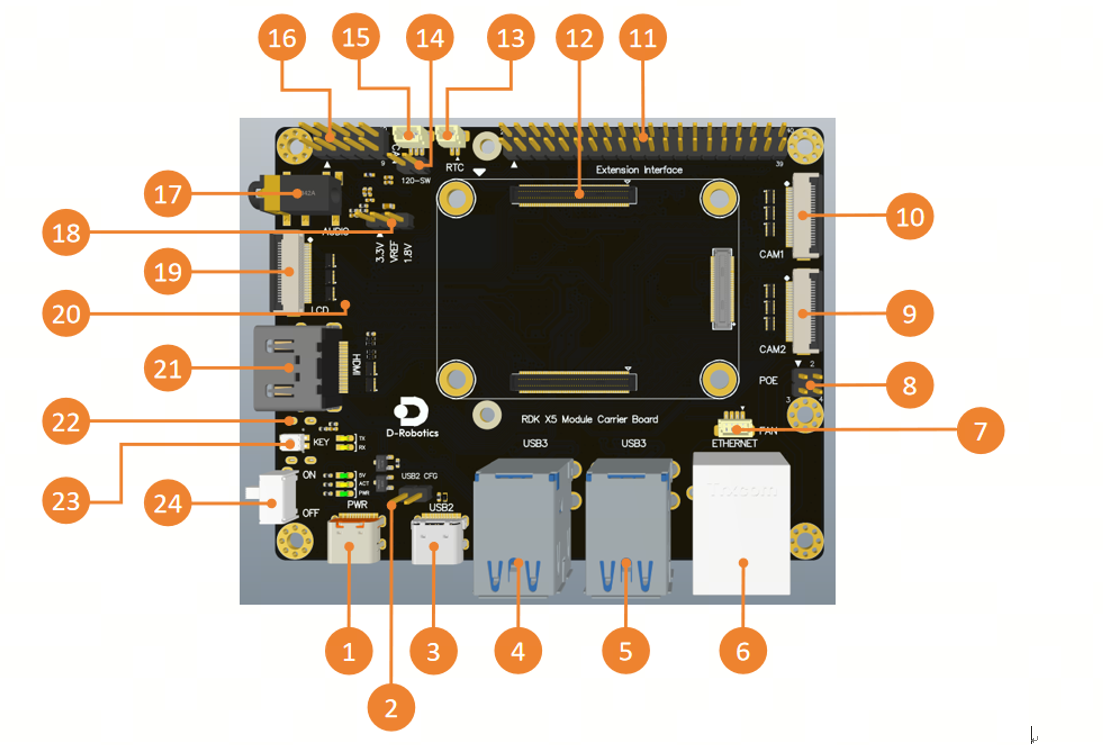
| No. | Function | No. | Function | No. | Function |
|---|---|---|---|---|---|
| 1 | USB Type-C 5V/5A power supply | 9 | CAM2 interface, 4-lane | 17 | Audio interface |
| 2 | USB 2.0 configuration header | 10 | CAM1 interface, 4-lane | 18 | IO voltage selection header |
| 3 | USB 2.0 interface | 11 | 40-pin header | 19 | MIPI DSI interface |
| 4 | USB 3.0 HOST interfaces x2 | 12 | Core module interface | 20 | Micro SD card slot (rear) |
| 5 | USB 3.0 HOST interfaces x2 | 13 | RTC battery interface | 21 | HDMI interface |
| 6 | Gigabit Ethernet port | 14 | CAN termination resistor switch | 22 | Debug port, USB-to-serial (rear) |
| 7 | Fan interface | 15 | CAN bus interface | 23 | Sleep button |
| 8 | POE interface | 16 | Functional control IO header | 24 | Power switch |
When the RTC is powered by a battery, the voltage and discharge current requirements for the battery are: 2~3.3V and >2.5uA. After the device is powered on, if the PMIC detects that the RTC voltage is low and reaches the charging voltage, it will automatically charge the RTC. The battery requirements are: the maximum chargeable voltage must be ≥3.3V, and the maximum allowable charging current must be >1mA. Additionally, an RTC that is not being charged must not be used for power supply.
SoM (System on Module) Interface
None。
The RDK X5 Module serves as the core board, integrating the D-Robotics Sunrise®5 intelligent computing chip and its key circuit design. It incorporates essential functional units such as the PMIC power management module, DDR, eMMC, QSPI NAND, Wi-Fi/Bluetooth, and more.
The core board provides a 300-pin high-speed expansion interface, which can flexibly connect to various peripherals, enabling rapid deployment in different application scenarios.
During installation, it is essential to ensure the correct orientation and alignment to avoid damage to the connectors on the core module or the carrier board.

Module installation steps:
- Check the pin layout of the core module to ensure the correct orientation.
- Place the core module directly above the carrier board and align the four positioning holes.
- Press down gently from the center of the module; when a clicking sound is heard, the module is properly seated.
Power Interface
The development board provides a USB Type C interface (No. 1) as the power interface. It requires a 5V/5A power adapter for supplying power to the board. Once the adapter is connected, the green power indicator and the orange indicator will blink, indicating normal power supply.
The development board provides a USB Type C interface (No. 1) as the power interface. It requires a 5V/5A power adapter for supplying power to the board. Once the adapter is connected, the green power indicator and the orange indicator will light up, indicating normal power supply.
Do not use a computer USB port to power the board. Insufficient power may cause abnormal shutdown or repeated reboots.
Debug Serial Port
The development board includes a debug serial port (No. 4) for serial login and debugging functions. Configure the parameters in the serial tool on your computer as follows:
- Baud rate: 115200
- Data bits: 8
- Parity: None
- Stop bits: 1
- Flow control: None
To connect, use a Micro USB cable to link the board's Interface 4 to your PC.
For first-time use, you may need to install the CH340 driver on your computer. Search for CH340 serial port driver to download and install it.
During the kernel boot stage, the baud rate configuration is defined in the /boot/boot.cmd file.
After modifying the serial port settings, you need to regenerate the boot.scr file using the following command:
mkimage -C none -A arm -T script -d boot.cmd boot.scr
The development board includes a debug serial port (No. 22) for serial login and debugging functions. Configure the parameters in the serial tool on your computer as follows:
- Baud rate: 921600
- Data bits: 8
- Parity: None
- Stop bits: 1
- Flow control: None
To connect, use a Micro USB cable to link the board's Interface 4 to your PC.
For first-time use, you may need to install the CH340 driver on your computer. Search for CH340 serial port driver to download and install it.
During the kernel boot stage, the baud rate configuration is defined in the /boot/boot.cmd file.
After modifying the serial port settings, you need to regenerate the boot.scr file using the following command:
mkimage -C none -A arm -T script -d boot.cmd boot.scr
Ethernet Port
The development board features a Gigabit Ethernet port (No. 6) supporting 1000BASE-T and 100BASE-T standards. By default, it uses a static IP configuration with the address 192.168.127.10.
To verify the board's IP address, log in via the serial port and use the ifconfig command to check the configuration of the eth0 interface.
Additionally, this port supports PoE (Power over Ethernet), allowing simultaneous data and power transmission via a single Ethernet cable for easier installation.
HDMI Display Interface
The development board includes an HDMI display (Interface 10) that supports a maximum resolution of 1080p. Using the HDMI interface, the board can output the Ubuntu system desktop (on the Ubuntu Server version, it displays the logo).
The HDMI interface also supports real-time display of camera and network stream images.
The development board includes an HDMI display (Interface 21) that supports a maximum resolution of 1080p. Using the HDMI interface, the board can output the Ubuntu system desktop (on the Ubuntu Server version, it displays the logo).
The HDMI interface also supports real-time display of camera and network stream images.
USB Interfaces
The development board supports multiple USB interface extensions to accommodate various USB devices. Details are as follows:
| Interface Type | Interface No. | Quantity | Description |
|---|---|---|---|
| USB 2.0 Type C | No. 3 | 1 port | USB Device mode for ADB, Fastboot, system flashing, etc. |
| USB 3.0 Type A | No. 7 | 4 ports | USB Host mode for connecting USB 3.0 peripherals, expanding 4 USB ports through a hub. |
The development board supports multiple USB interface extensions to accommodate various USB devices. Details are as follows:
| Interface Type | Interface No. | Quantity | Description |
|---|---|---|---|
| USB 2.0 Type C | No. 3 | 1 port | USB Device mode for ADB, Fastboot, system flashing, etc. |
| USB 3.0 Type A | No. 4 & 5 | 4 ports | USB Host mode for connecting USB 3.0 peripherals, expanding 4 USB ports through a hub. |
USB 2.0 interface to HOST mode
The development board can be shorted (No. 2) to switch the USB 2.0 interface to HOST mode.
Connecting USB Flash Drives
The USB Type A ports (Interface 7) support USB flash drives, which will be automatically detected and mounted. The default mount directory is /media/sda1.
Connecting USB-to-Serial Adapters
The USB Type A ports (Interface 7) support USB-to-serial adapters, which will be automatically detected and create device nodes such as /dev/ttyUSB* or /dev/ttyACM* (where the asterisk represents a number starting from 0). Refer to the 40-pin UART Usage section for details.
Connecting USB Cameras
The USB Type A ports support USB cameras, which will be automatically detected and create device nodes such as /dev/video0.
IO Voltage Selection
None.
The development board provides an IO voltage selection interface (corresponding to interface No. 18), which allows switching the IO voltage between 1.8V and 3.3V. This setting simultaneously affects the IO voltage levels of both the 40-pin interface and the CAM interfaces.
MIPI Camera Interface
The development board provides two MIPI CSI interfaces (No. 5) for connecting up to two MIPI cameras, including stereo cameras. Compatible camera modules and specifications are as follows:
| No. | Sensor | Resolution | FOV | I2C Device Address |
|---|---|---|---|---|
| 1 | IMX219 | 8 MP | ||
| 2 | OV5647 | 5 MP | ||
| 2 | IMX477 | 12 MP |
The camera module is connected to the development board via a 22-pin same-direction flexible cable, with the metal side of the cable inserted into the connector facing away from the black buckle.
After installation, users can use the i2cdetect command to confirm whether the module's I2C address can be detected normally.
Query the I2C device address of the Camera Sensor on the mipi_host0 interface near the Ethernet port:
echo 353 > /sys/class/gpio/export
echo out > /sys/class/gpio/gpio353/direction
echo 0 > /sys/class/gpio/gpio353/value
sleep 0.1
echo 1 > /sys/class/gpio/gpio353/value

i2cdetect -y -r 6
Query the I2C device address of the Camera Sensor on the mipi_host2 interface far from the network port:
echo 351 > /sys/class/gpio/export
echo out > /sys/class/gpio/gpio351/direction
echo 0 > /sys/class/gpio/gpio351/value
sleep 0.1
echo 1 > /sys/class/gpio/gpio351/value

i2cdetect -y -r 4
When the I2C device address of the Camera Sensor is successfully detected, the following print can be seen (taking the detection of IMX219 on the interface mipi_host2 as an example, it can be observed that the address 10 is printed):
root@ubuntu:~# i2cdetect -y -r 4
     0  1  2  3  4  5  6  7  8  9  a  b  c  d  e  f
00:                         -- -- -- -- -- -- -- --
10: 10 -- -- -- -- -- -- -- -- -- -- -- -- -- -- --
20: -- -- -- -- -- -- -- -- -- -- -- -- -- -- -- --
30: -- -- -- -- -- -- -- -- -- -- -- -- -- -- -- --
40: -- -- -- -- -- -- -- -- -- -- -- -- -- -- -- --
50: -- -- -- -- -- -- -- -- -- -- -- -- -- -- -- --
60: -- -- -- -- -- -- -- -- -- -- -- -- -- -- -- --
70: -- -- -- -- -- -- -- --
The development board provides 2 22-pin MIPI CSI interfaces (No. 10 and 9) for connecting up to two MIPI cameras, including stereo cameras. Compatible camera modules and specifications are as follows:
| No. | Sensor | Resolution | FOV | I2C Device Address |
|---|---|---|---|---|
| 1 | IMX219 | 8 MP | ||
| 2 | OV5647 | 5 MP | ||
| 2 | IMX477 | 12 MP |
The IO voltage (interface No. 18) should be set to 3.3V.
Connect the camera module to the board using an FFC (Flat Flex Cable) with the blue side facing upwards.
After installation, use the i2cdetect command to check if the I2C address of the module can be detected.
Important: Do not connect or disconnect the camera while the board is powered on, as this may damage the camera module.
LCD Display Interface
The RDK X5 provides an LCD display interface (MIPI DSI, Interface 14) that supports LCD screens. This interface is 22-pin and can use DSI-Cable-12cm to directly connect to various LCD displays for Raspberry Pi.
Micro SD Interface
The development board includes a Micro SD card interface (Interface 13). It is recommended to use a card with at least 16GB of storage to meet the installation requirements of Ubuntu and related packages.
The development board includes a Micro SD card interface (Interface 19). It is recommended to use a card with at least 16GB of storage to meet the installation requirements of Ubuntu and related packages.
Micro SD Interface
The development board provides one Micro SD card interface (interface No. 13). It is recommended to use a storage card with a capacity of at least 16GB to accommodate the installation of the Ubuntu operating system and related packages.
The development board provides one Micro SD card interface (interface No. 22). It is recommended to use a storage card with a capacity of at least 16GB to accommodate the installation of the Ubuntu operating system and related packages.
Do not hot-swap the TF card during use, as it may cause system abnormalities or file system corruption.
Wi-Fi Antenna Interface
The board supports both onboard and external antennas for wireless networking. The onboard antenna is sufficient for most scenarios. If the board is enclosed in a metal casing, connect an external antenna to the port near Interface 12 to enhance signal strength.
Antenna Interface Specifications:
- Interface Type: IPEX 1st Generation
- Frequency: Supports 2.4GHz/5GHz Wi‑Fi Transmission
The wireless network of the development board uses an external antenna configuration, requiring the external antenna to be connected to the core board to enhance signal strength.
Antenna Interface Specifications:
- Interface Type: IPEX 1st Generation
- Frequency: Supports 2.4GHz/5GHz Wi‑Fi Transmission
CAN FD Interface
The RDK X5 provides a CAN FD interface for CAN and CAN FD communication. Refer to the CAN Usage section for details.
The RDK X5 Module development board provides a CAN FD interface (interface No. 15) and a CAN termination resistor switch (interface No. 14). For high-speed communication, both termination resistors should be enabled to prevent signal reflections and improve noise immunity. This setup supports both CAN and CAN FD communication. For detailed information, please refer to the relevant documentation. CAN使用
40-pin GPIO Interface
The development board includes a 40-pin GPIO interface with IO signals using a 3.3V logic level design. The pin definition is compatible with Raspberry Pi and similar products. For detailed pin definitions and multiplexing information, please refer to the 40-pin GPIO Function Usage section.
The development board includes a 40-pin GPIO interface with IO signals using a 3.3V logic level design. The pin definition is compatible with Raspberry Pi and similar products. For detailed pin definitions and multiplexing information, please refer to the 40-pin GPIO Function Usage section.
All IO pins on the 40-pin header support switching between 3.3V and 1.8V voltage domains via the IO voltage selection interface (interface No. 18).
Connector Models
| Connector | Model | Vendor | Description |
|---|---|---|---|
| J1 | HDGC1002WV-S-2P | HDGC | RTC Battery Interface |
| J14/J15 | AFC11-S22ICA-00 | jushuodz | MIPI Camera Interface |
| J16 | AFC01-S22FCA-00 | jushuodz | LCD Display Interface |
| J18 | HDGC1002WV-S-3P | HDGC | CAN FD Interface |
| Connector | Model | Vendor | Description |
|---|---|---|---|
| J1/J21 | DF40C-100DS-0.4V(51) | hirose | 100P Connector |
| J3 | DF40C-60DS-0.4V(51) | hirose | 60P Connector |
| J4 | PZ254V-12-10P | XFCN | Function Control IO Header |
| J5 | WAFER-SH1.0-2PLB | XFCN | RTC Battery Interface |
| J7/J8/J10 | FPC-05F-22PH20 | XUNPU | CAM Interface, MIPI DSI |
| J15 | WAFER-SH1.0-4PLB | XUNPU | Fan Interface |
| J18 | WAFER-SH1.0-3PLB | XUNPU | CAN |
| J20 | PH2.54-01-02PZS | XUNPU | POE |
Interface Power Load Capacity
The following values indicate the maximum load current supported by a single interface. When multiple interfaces are used concurrently, the available current per interface may be reduced.
| Interface | Power Capacity |
|---|---|
| CAN Interface | 500mA @ 3.3V |
| DSI Interface | 500mA @ 3.3V |
| 40Pin Interface | 1A @ 3.3V/1A @ 5V |
| USB3 Interface | 1A @ 5V |
| Interface | Power Capacity |
|---|---|
| CAN Interface | 500mA @ 3.3V |
| DSI Interface | 500mA @ 3.3V |
| 40Pin Interface | 1A @ 3.3V/1A @ 5V |
| USB3 Interface | 1A @ 5V |