Watchdog
Watchdog Overview
Watchdog supports window mode and normal mode. In normal mode, the watchdog must be fed before the timer counts down to zero. In window mode, feeding is required within a specific window period. The window period is between the first timeout and the second timeout. An interrupt signal can be configured to be generated at the first timeout. If feeding is not performed within the window period or is performed outside the window period, a watchdog reset signal is sent to the MCU, which then controls the reset. The SoC includes 13 watchdogs, distributed as follows: Acore has 6, MCU has 3, VDSP has 1, BPU has 2, and HSM has 1. The specific usage of the Acore Watchdog is shown in the table below:
| Watchdog0 | Reserved for customers |
| Watchdog1 | Monitors Acore IRQ response timeout, Timeout is 161ms |
| Watchdog2 | Monitors Acore Kthread response timeout, Timeout is 5162ms |
| Watchdog3 | Reserved for customers |
| Watchdog4 | Reserved for customers |
| Watchdog5 | Reserved for customers |
Watchdog supports window mode and normal mode. In normal mode, the watchdog must be fed before the timer counts down to zero. In window mode, feeding is required within a specific window period. The window period is between the first timeout and the second timeout. An interrupt signal can be configured to be generated at the first timeout. If feeding is not performed within the window period or is performed outside the window period, a watchdog reset signal is sent to the MCU, which then controls the reset. The SoC includes 18 watchdogs, distributed as follows: Acore has 2, MCU has 5, VDSP has 2, BPU has 8, and HSM has 1. The specific usage of the Acore Watchdog is shown in the table below:
| Watchdog0 | Monitors Acore IRQ response timeout, Timeout is 161ms |
| Watchdog1 | Monitors Acore Kthread response timeout, Timeout is 5162ms |
Features
A window watchdog is a special type of watchdog commonly used in functional safety products.
-
Window refers to a change in the mechanism where a reset signal was originally reported after a single timeout when window mode is enabled.
-
Before the first timeout is the forbidden zone. Feeding is not allowed during this period; otherwise, a reset signal will be reported.
-
Between the first and second timeouts is the allowed zone. Feeding is permitted during this period. A timeout without feeding will report a reset signal.

Device Tree
Add the hardware information description of the watchdog to the device tree (location: code/source/hobot-drivers/kernel-dts/arch/arm64/boot/dts/hobot/drobot-s100-soc.dtsi)
  watchdog1: wdt@30110000 {
          status = "okay";
          ranges;
          #address-cells = <2>;
          #size-cells = <2>;
          compatible = "snps,hb_wdt";
          reg = <0x0 0x30110000 0x0 0x1000>;  //the register address of the hardware
          interrupt-parent = <&gic>;
          interrupts = <GIC_SPI CPUSYS_CLUSTER_MP4_WWDT_WDT_INTR_1 IRQ_TYPE_LEVEL_HIGH>,
          <GIC_SPI CPUSYS_CLUSTER_MP4_WWDT_SYS_RST_INTR_1 IRQ_TYPE_EDGE_RISING>;
          clocks = <&scmi_smc_clk CLK_IDX_TOP_CPU0_TIMER_WDT>;
          resets = <&smc_reset RST_IDX_IP_CPU0_WWDT_PAUSE1>,
                          <&smc_reset RST_IDX_IP_CPU0_WWDT_1>;
          snps,mode = "sw";
          usage = "irq_mon";
          timeout = <161>;         //  timeout 161ms
          moduleid-ofst = <5>;
          wdt_tee_regmap {
                  compatible = "syscon";
                  services = <&tee_regmap>;
                  reg = <0x0 0x300A0000 0x0 0x10000>;
          };
  };
Device Tree
Add the hardware information description of the watchdog to the device tree (location: code/source/hobot-drivers/kernel-dts/arch/arm64/boot/dts/hobot/drobot-s600-soc.dtsi)
  watchdog0: wdt@32260000 {
          status = "okay";
          ranges;
          #address-cells = <2>;
          #size-cells = <2>;
          compatible = "snps,hb_wdt";
          reg = <0x0 0x32260000 0x0 0x1000>;
          interrupt-parent = <&gic>;
          interrupts = <GIC_SPI CPUSYS_MP2_CLUSTER_MP2_WWDT_WDT_INTR_0 IRQ_TYPE_LEVEL_HIGH>,
          <GIC_SPI CPUSYS_MP2_CLUSTER_MP2_WWDT_SYS_RST_INTR_0 IRQ_TYPE_EDGE_RISING>;
          clocks = <&clk_26m>;
          resets = <&smc_reset RST_IDX_WWDT_PAUSE_MP2_0>,
              <&smc_reset RST_IDX_WWDT_SOFT_RESET_MP2_0>;
          snps,mode = "sw";
          usage = "irq_mon";
          timeout = <161>;
          moduleid-ofst = <5>;
          wdt_tee_regmap {
            compatible = "syscon";
            services = <&tee_regmap>;
            reg = <0x0 0x32220000 0x0 0x10000>;
          };
		};
Watchdog Driver Code
The driver code for the Watchdog module is located at /hobot-drivers/watchdog.
Watchdog Timeout
When a Watchdog timeout monitoring the Acore occurs, an interrupt is triggered and sent to the MCU0 side. A task on the MCU then triggers an Acore restart. The task waits for 5 seconds to allow the Acore side to complete stack dumping.

User Development
Currently, WDT1 is used to monitor kernel interrupt disable timeouts, WDT2 is used to monitor kernel threads, and the remaining WDT0, WDT3, WDT4, and WDT5 can be operated from user space via the ioctl interface as shown below. Currently, WDT0 is used to monitor kernel interrupt disable timeouts, and WDT1 is used to monitor kernel threads.
hb_wdt_ioctl.h Description
Before using the ioctl interface described in this document in a user-space program, you need to prepare the header file hb_wdt_ioctl.h. In the header file:
WDT_MAGIC_NUM: Takes the character'W'as its value, used to mark that the followingioctlcommands are for the watchdog. Different peripherals/drivers use different markers so that the kernel does not confuse commands for other devices with those for the watchdog (this value should not be changed; keep it consistent with the driver).HB_WDT_START,HB_WDT_RESTART, etc.: Specific command numbers distinguished under the'W'marker, corresponding to the subsections below.
The above definitions must remain consistent with the kernel watchdog character device driver.
File Content
You can save the following content as hb_wdt_ioctl.h:
#ifndef DRIVERS_WATCHDOG_HB_WDT_IOCTL_H_
#define DRIVERS_WATCHDOG_HB_WDT_IOCTL_H_

#define WDT_MAGIC_NUM 'W'  /**< ioctl magic num*/
#define HB_WDT_START					_IO(WDT_MAGIC_NUM, 1)  /**< ioctl cmd to start*/
#define HB_WDT_STOP						_IO(WDT_MAGIC_NUM, 2)  /**< ioctl cmd to stop*/
#define HB_WDT_RESTART					_IO(WDT_MAGIC_NUM, 3)  /**< ioctl cmd to restart*/
#define HB_WDT_GETSTATUS			    _IO(WDT_MAGIC_NUM, 4)  /**< ioctl cmd to get status*/
#define HB_WDT_SETTIMEOUT				_IO(WDT_MAGIC_NUM, 5)  /**< ioctl cmd to set timeout*/
#define HB_WDT_GETTIMEOUT				_IO(WDT_MAGIC_NUM, 6)  /**< ioctl cmd to get timeout*/
#define HB_WDT_GETTIMELEFT				_IO(WDT_MAGIC_NUM, 7)  /**< ioctl cmd to get timeleft*/
#define HB_WDT_SETMODE			        _IO(WDT_MAGIC_NUM, 8)  /**< ioctl cmd to set mode*/
#define HB_WDT_GETMODE			        _IO(WDT_MAGIC_NUM, 9)  /**< ioctl cmd to get mode*/
#define HB_WDT_PAUSE        			_IO(WDT_MAGIC_NUM, 10)  /**< ioctl cmd to pause*/
#define HB_WDT_PROCEED          		_IO(WDT_MAGIC_NUM, 11)  /**< ioctl cmd to proceed*/

#endif
Usage
- In the Linux user space,
_IOis defined in<sys/ioctl.h>. If the compiler indicates that_IOis undefined, add#include <sys/ioctl.h>before includinghb_wdt_ioctl.h, or write this include insidehb_wdt_ioctl.hand place it before#define WDT_MAGIC_NUM. - After successfully opening the watchdog character device and obtaining a valid file descriptor
fd, includehb_wdt_ioctl.hand callioctl(fd, HB_WDT_xxx, &flags)as described in the following subsections of the manual. - If the driver side changes the
ioctlcommand numbers, you must synchronously update the macro definitions in this header file.
#include <sys/ioctl.h>
#include "hb_wdt_ioctl.h"

/* fd is the opened file descriptor for the watchdog character device */
int flags = 0;
ret = ioctl(fd, HB_WDT_START, &flags);
HB_WDT_START
int flags = 0;
ret = ioctl(fd, HB_WDT_START, &flags);
Function Description:
- Start the watchdog
Parameter Description:
- [IN] fd: WDT file descriptor
- [IN] HB_WDT_START: ioctl macro for WDT START
- [IN/OUT] flags: Reserved parameter; pass 0
Return Value:
- 0: Success
- Less than 0: Failure
HB_WDT_STOP
int flags = 0;
ret = ioctl(fd, HB_WDT_STOP, &flags);
Function Description:
- Stop the watchdog
Parameter Description:
- [IN] fd: WDT file descriptor
- [IN] HB_WDT_STOP: ioctl macro for WDT STOP
- [IN/OUT] flags: Reserved parameter; pass 0
Return Value:
- 0: Success
- Less than 0: Failure
HB_WDT_RESTART
int flags = 0;
ret = ioctl(fd, HB_WDT_RESTART, &flags);
Function Description:
- Feed the watchdog
Parameter Description:
- [IN] fd: WDT file descriptor
- [IN] HB_WDT_RESTART: ioctl macro for WDT RESTART
- [IN/OUT] flags: Reserved parameter; pass 0
Return Value:
- 0: Success
- Less than 0: Failure
HB_WDT_PAUSE
int flags = 0;
ret = ioctl(fd, HB_WDT_PAUSE, &flags);
Function Description:
- Pause the watchdog
Parameter Description:
- [IN] fd: WDT file descriptor
- [IN] HB_WDT_PAUSE: ioctl macro for WDT PAUSE
- [IN/OUT] flags: Reserved parameter; pass 0
Return Value:
- 0: Success
- Less than 0: Failure
HB_WDT_PROCEED
int flags = 0;
ret = ioctl(fd, HB_WDT_PROCEED, &flags);
Function Description:
- Resume the watchdog after it has been paused
Parameter Description:
- [IN] fd: WDT file descriptor
- [IN] HB_WDT_PROCEED: ioctl macro for WDT PROCEED
- [IN/OUT] flags: Reserved parameter; pass 0
Return Value:
- 0: Success
- Less than 0: Failure
HB_WDT_SETTIMEOUT
int flags = 50;// Input: timeout value in milliseconds (e.g., 50)
ret = ioctl(fd, HB_WDT_SETTIMEOUT, &flags);
Function Description:
- Set the watchdog timeout in milliseconds
Parameter Description:
- [IN] fd: WDT file descriptor
- [IN] HB_WDT_SETTIMEOUT: ioctl macro for WDT SETTIMEOUT
- [IN] flags: Timeout value to set, in milliseconds
Return Value:
- 0: Success
- Less than 0: Failure
HB_WDT_GETTIMEOUT
int flags = 0;
ret = ioctl(fd, HB_WDT_GETTIMEOUT, &flags);
Function Description:
- Get the watchdog timeout in milliseconds
Parameter Description:
- [IN] fd: WDT file descriptor
- [IN] HB_WDT_GETTIMEOUT: ioctl macro for WDT GETTIMEOUT
- [OUT] flags: Retrieved watchdog timeout value, in milliseconds
Return Value:
- 0: Success
- Less than 0: Failure
HB_WDT_GETTIMELEFT
int flags = 0;
ret = ioctl(fd, HB_WDT_GETTIMELEFT, &flags);
Function Description:
- Get the remaining timeout in the current watchdog feeding cycle, in milliseconds
Parameter Description:
- [IN] fd: WDT file descriptor
- [IN] HB_WDT_GETTIMELEFT: ioctl macro for WDT GETTIMELEFT
- [OUT] flags: Retrieved remaining timeout in the current feeding cycle, in milliseconds
Return Value:
- 0: Success
- Less than 0: Failure
HB_WDT_SETMODE
int flags = 34;
ret = ioctl(fd, HB_WDT_SETMODE, &flags);
Function Description:
- Set the watchdog mode
Parameter Description:
- [IN] fd: WDT file descriptor
- [IN] HB_WDT_SETMODE: ioctl macro for WDT SETMODE
- [IN] flags: Watchdog mode to set. 34 indicates window mode with first timeout interrupt, 2 indicates window mode without first timeout interrupt, 0 indicates normal mode
Return Value:
- 0: Success
- Less than 0: Failure
HB_WDT_GETMODE
int flags = 0;
ret = ioctl(fd, HB_WDT_GETMODE, &flags);
Function Description:
- Get the watchdog mode
Parameter Description:
- [IN] fd: WDT file descriptor
- [IN] HB_WDT_GETMODE: ioctl macro for WDT GETMODE
- [OUT] flags: Retrieved watchdog mode. 34 indicates window mode with first timeout interrupt, 2 indicates window mode without first timeout interrupt, 0 indicates normal mode
Return Value:
- 0: Success
- Less than 0: Failure
HB_WDT_GETSTATUS
int flags = 0;
ret = ioctl(fd, HB_WDT_GETSTATUS, &flags);
Function Description:
- Get the watchdog status
Parameter Description:
- [IN] fd: WDT file descriptor
- [IN] HB_WDT_GETSTATUS: ioctl macro for WDT GETSTATUS
- [OUT] flags: Retrieved watchdog status. bit0 = 1 indicates watchdog is enabled, bit0 = 0 indicates disabled; bit1 = 1 indicates watchdog is paused, bit1 = 0 indicates not paused; bit2 = 1 indicates nowayout is set, bit2 = 0 indicates nowayout is not set
Return Value:
- 0: Success
- Less than 0: Failure
Watchdog Monitoring Solutions
HardLockup Monitoring
HardLockup monitoring is implemented based on the Watchdog module, using Watchdog1 configured in window mode, with the monitoring logic implemented in the driver. When the system is running normally, the monitoring logic is as shown below:
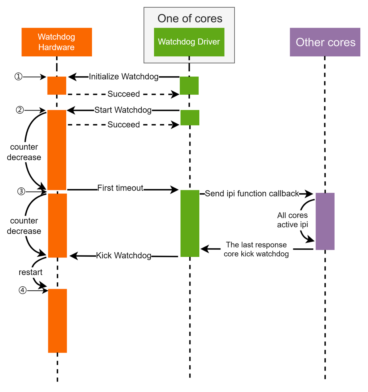
-
Initialize the Watchdog hardware.
-
Start the Watchdog timer.
-
When the first timeout occurs, an interrupt is generated. The Watchdog restarts counting. A core responds to the interrupt and sends IPIs to other cores, recording a bitmap of CPUs currently online. Whenever a core receives the IPI interrupt or goes offline, the corresponding bit in the bitmap is cleared. When the entire bitmap is empty, the monitoring task for this cycle is complete, and feeding the watchdog is allowed.
-
After feeding, the Watchdog starts the next counting cycle.

-
Initialize the Watchdog hardware.
-
Start the Watchdog timer.
-
When the first timeout occurs, an interrupt is generated. The Watchdog restarts counting. A core responds to the interrupt and sends IPIs to other cores. If the CPU bitmap is not empty, it indicates that some cores cannot respond to IRQ interrupts normally, and feeding is not allowed.
-
The Watchdog counter continues to decrement. When the second timeout occurs, two interrupts are generated: one is sent to the Acore's GIC to trigger a stack dump, and the other is a watchdog reset interrupt sent to the MCU, which then controls the reset. Upon first receiving the watchdog reset interrupt corresponding to a bark, the MCU refreshes the watchdog timeout to 2581ms to allow the Acore time to dump the stack. When the watchdog reset interrupt is triggered again, a reset is performed.
SoftLockup Monitoring
SoftLockup monitoring is implemented based on the Watchdog module, using Watchdog2 configured in window mode, with the monitoring logic implemented in the driver. The overall monitoring concept is consistent with HardLockup monitoring.
-
Initialize the Watchdog hardware.
-
Initialize the per-CPU Watchdog monitoring Kthread threads, meaning each CPU runs a Watchdog monitoring Kthread.
-
Start the Watchdog timer.
-
When the first timeout occurs, an interrupt is generated. The Watchdog restarts counting. A core responds to the interrupt and sets a flag. The Watchdog monitoring Kthread running on that core detects the flag, clears its own bit in the CPU bitmap, and sends IPIs to other cores to execute the same logic. It records a bitmap of currently online CPUs. Whenever a core receives the IPI, executes the logic, or goes offline, the corresponding bit in the bitmap is cleared. When the entire bitmap is empty, the monitoring task for this cycle is complete, and feeding the watchdog is allowed.
-
If the CPU bitmap is still not empty before the second timeout, two interrupts are generated when the second timeout occurs: one is sent to the Acore's GIC to trigger a stack dump, and the other is a watchdog reset interrupt sent to the MCU, which then controls the reset. Upon first receiving the watchdog reset interrupt corresponding to a bark, the MCU refreshes the watchdog timeout to 2581ms to allow the Acore time to dump the stack. When the watchdog reset interrupt is triggered again, a reset is performed.
HardLockup Monitoring
HardLockup monitoring is implemented based on the Watchdog module, using Watchdog0 configured in window mode, with the monitoring logic implemented in the driver. When the system is running normally, the monitoring logic is as shown below:
-
Initialize the Watchdog hardware.
-
Start the Watchdog timer.
-
When the first timeout occurs, an interrupt is generated. The Watchdog restarts counting. A core responds to the interrupt and sends IPIs to other cores, recording a bitmap of CPUs currently online. Whenever a core receives the IPI interrupt or goes offline, the corresponding bit in the bitmap is cleared. When the entire bitmap is empty, the monitoring task for this cycle is complete, and feeding the watchdog is allowed.
-
After feeding, the Watchdog starts the next counting cycle.
-
Initialize the Watchdog hardware.
-
Start the Watchdog timer.
-
When the first timeout occurs, an interrupt is generated. The Watchdog restarts counting. A core responds to the interrupt and sends IPIs to other cores. If the CPU bitmap is not empty, it indicates that some cores cannot respond to IRQ interrupts normally, and feeding is not allowed.
-
The Watchdog counter continues to decrement. When the second timeout occurs, two interrupts are generated: one is sent to the Acore's GIC to trigger a stack dump, and the other is a watchdog reset interrupt sent to the MCU, which then controls the reset. Upon first receiving the watchdog reset interrupt corresponding to a bark, the MCU refreshes the watchdog timeout to 2581ms to allow the Acore time to dump the stack. When the watchdog reset interrupt is triggered again, a reset is performed.
SoftLockup Monitoring
SoftLockup monitoring is implemented based on the Watchdog module, using Watchdog1 configured in window mode, with the monitoring logic implemented in the driver. The overall monitoring concept is consistent with HardLockup monitoring.
-
Initialize the Watchdog hardware.
-
Initialize the per-CPU Watchdog monitoring Kthread threads, meaning each CPU runs a Watchdog monitoring Kthread.
-
Start the Watchdog timer.
-
When the first timeout occurs, an interrupt is generated. The Watchdog restarts counting. A core responds to the interrupt and sets a flag. The Watchdog monitoring Kthread running on that core detects the flag, clears its own bit in the CPU bitmap, and sends IPIs to other cores to execute the same logic. It records a bitmap of currently online CPUs. Whenever a core receives the IPI, executes the logic, or goes offline, the corresponding bit in the bitmap is cleared. When the entire bitmap is empty, the monitoring task for this cycle is complete, and feeding the watchdog is allowed.
-
If the CPU bitmap is still not empty before the second timeout, two interrupts are generated when the second timeout occurs: one is sent to the Acore's GIC to trigger a stack dump, and the other is a watchdog reset interrupt sent to the MCU, which then controls the reset. Upon first receiving the watchdog reset interrupt corresponding to a bark, the MCU refreshes the watchdog timeout to 2581ms to allow the Acore time to dump the stack. When the watchdog reset interrupt is triggered again, a reset is performed.
Important Notes
- The reset method for watchdog feeding timeouts is determined by the watchdog reset register configuration. Currently, reset is handled by the watchdog reset interrupt reported to the MCU driver software.
- Feeding the watchdog outside the window period will directly trigger a bark.