Audio Debugging Guide
This chapter mainly covers the specifications and features of I2S, basic audio knowledge, and instructions for adding codecs and debugging sound cards.
Overview
CPU DAI: The digital audio interface on the CPU side, typically an I2S interface, responsible for control bus transmission.
CODEC DAI: Refers to the codec. Controls the codec workflow and provides it to the core layer.
DAI LINK: Binds the CPU DAI and CODEC DAI, referring to the hardware controller driver.
PLATFORM: Specifies the platform driver on the CPU side, usually a DMA driver used for data transmission.
DAPM: Dynamic Audio Power Management.
Audio Development Instructions
A complete sound card consists of a CPU DAI, a CODEC DAI, a platform, and a sound card.
CPU DAI driver: Typically an I2S interface driver.
CODEC DAI driver: Refers to the external codec driver.
Platform driver: Usually a DMA driver, used to manage audio data.
Sound card driver: Responsible for connecting the CPU DAI and the CODEC DAI, for example, sound/soc/hobot/hobot-snd-super-ac-fdx-host.c.
I2S Parameter Description
I2S chip capabilities:
- Channel support: Supports 1/2/4/8/16 channels.
- Sampling rate support: 8k/16k/32k/48k/44.1k/96k/192k.
- Sample precision support: 8bit/16bit/24bit/32bit.
- Transmission protocol support: I2S/DSP(TDM).
- I2S supports configuration as master or slave mode.
- The sysclk of the I2S module needs to be at least 6 times the bclk.
- Supports full-duplex mode. In full-duplex mode, sdio0 is input and sdio1 is output, which cannot be changed.
- The bclk output cannot exceed 25MHz.
Instructions for Adding a New Codec
Adding a Codec Driver
Add the codec driver file to the sound/soc/codecs/ directory.
Adding Compilation Options
- Add the compilation configuration for the codec driver by modifying sound/soc/codec/Kconfig and the Makefile.
Refer to the following for additions to Kconfig:
config SND_SOC_ES7210
        tristate "ES7210 Audio Codec"
        depends on I2C
Refer to the following for additions to the Makefile:
obj-$(CONFIG_SND_SOC_ES7210) += snd-soc-es7210.o
- Modify the config configuration via menuconfig to enable compilation.
sudo ./mk_kernel.sh menuconfig
After executing the above command, open the Kernel Configuration interface, enter CONFIG_SND_SOC_ES7210 and enable it.
Modifying the DTS
Modifying the DTS generally involves the following:
- Adding the codec driver node. The codec registers are typically controlled via I2C. Knowing which I2C bus the codec is mounted on, add the codec information to the corresponding I2C node. Refer to the following:
i2c5: i2c@39470000 {
    es7210_0: es7210_0@40 {
            compatible = "MicArray_0";
            reg = <0x40>;
            #sound-dai-cells = <1>;
            channels = <8>;
            adc_dev_num = <2>;
            status = "okay";
    };
};
- Adding the sound card node. Establish the DAI link binding relationship between the codec and I2S. Refer to the following:
snd2: snd2 {
        status = "okay";
        model = "s100snd2";
        compatible = "hobot, super-snd-ac-fdx-master";
        i2s_mode = <1>;/*1:i2s mode; 7:dsp_a mode*/
        work_mode = <1>;/*0:hal-duplex; 1:full-duplex*/
        channel_max = <2>;
        mclk_set = <24576000>;
        dai-link@0 {
                dai-format = "dsp_a"; //"i2s"/"dsp_a" //corresponds to SND_SOC_DAIFMT_DSP_A
                // bitclock-master; /configure *-master, equivalent to SND_SOC_DAIFMT_CBM_CFM in dai_fmt. Indicates that the codec is designated as the master providing the clock source.
                // frame-master;
                // frame-inversion; //corresponds to SND_SOC_DAIFMT_NB_IF, inverts the polarity of the frame synchronization signal. Normally, the left channel corresponds to low level, and the right channel to high level. Enabling frame-inversion reverses the polarity.
                link-name = "s100dailink0";
                cpu {
                        sound-dai = <&i2s0 0>; //Digital audio interface, controls bus transmission
                };
                codec {
                        sound-dai = <&es7210_0 0>; //Codec chip interface
                };
        };

        dai-link@1 {
                dai-format = "dsp_a";
                link-name = "s100dailink1";
                cpu {
                        sound-dai = <&i2s0 1>;
                };
                codec {
                        sound-dai = <&es8156>;
                };
        };
};
- Additionally, a dummy_codec node is added in the DTS. In cases where there is no external codec or the codec requires separate configuration without relying on the ALSA framework, a sound card device is registered and bound to the virtual codec to create device nodes in user space for controlling I2S/DMA.
Debugging Instructions
Sound Card Debugging
The sound card debugging in this section is based on the solution using an external Waveshare audio daughter board.
The sound card module exists as a ko file by default and is loaded dynamically. The driver loading commands are as follows:
modprobe hobot_cpudai_super
modprobe snd-soc-es8156
modprobe snd-soc-es7210
modprobe hobot_snd_super_ac_fdx_host
Methods to verify if the sound card is loaded successfully after driver loading:
- Check the /proc/asound/cards node
root@ubuntu:/# cat /proc/asound/cards
 0 [s100snd2       ]: s100snd2 - s100snd2
                      s100snd2
- Check the /dev/snd/ node
root@ubuntu:/# ls -l /dev/snd
total 0
crw-rw-r--+ 1 root misc 116,  4 Apr 29 19:09 controlC0
crw-rw-r--+ 1 root misc 116,  2 Apr 29 19:09 pcmC0D0c
crw-rw-r--+ 1 root misc 116,  3 Apr 29 19:09 pcmC0D1p
Reference commands for functional testing after the sound card is loaded successfully:
arecord -Dhw:0,0 -c 2 -r 16000 -f S16_LE -t wav -d 5 test.wav
aplay -Dhw:0,1 test.wav
The PDMA driver restricts data size to 64-byte alignment.
It is particularly emphasized here that when configuring the period-size value, the set value must meet the byte alignment requirement.
For arecord/aplay, the corresponding parameter configuration is: --period-size=X
Common Debugging Methods
Adjusting Debug Log Levels
echo "8 4 1 7" > /proc/sys/kernel/printk
echo -n "file hhobot-cpudai-super.c +p" > /sys/kernel/debug/dynamic_debug/control
echo -n "file hobot-i2s-super.c +p" > /sys/kernel/debug/dynamic_debug/control
echo -n "file hobot-platform-super.c +p" > /sys/kernel/debug/dynamic_debug/control
ALSA Procfs Node Description
Procfs is a file system in Linux that provides an interface to kernel data structures. The mount directory is /proc.
The ALSA procfs mount directory is: /proc/asound. ALSA uses files in the /proc/asound directory to save device information and for control purposes. Through proc nodes, we can quickly view certain information to locate and debug issues encountered.
/proc/asound/cards
A list of registered sound cards. By checking this node, you can review the list of sound cards currently registered on the system or check whether a sound card has been registered successfully.
/proc/asound/pcm
Information about allocated PCM stream devices. By checking this node, you can find the list of devices supported by the current sound card. This helps in selecting how to set the card/device values for the device node during testing.
/proc/asound/cardX/pcmY[c, p]/*
Each PCM stream device corresponding to a sound card in the system has a procfs directory similar to the above. Here, X represents the sound card number, which can be confirmed via /proc/asound/cards or the device node information under /dev/snd. Y represents the device number, which can be confirmed via /proc/asound/pcm or the device node information under /dev/snd. c/p represent capture/playback respectively. This directory allows viewing of PCM device information and status.
info
General information about the PCM stream, such as sound card number, device number, stream type, bound codec type, etc.
hw_params
When the PCM stream is open, you can view the basic parameter configuration of the PCM, such as sampling rate, bit width, number of channels, period_size, buffer_size, etc. The configured period_size and buffer_size may differ from the values printed here. The actual hardware parameters are those shown here.
root@ubuntu:/proc/asound/card0/pcm0c/sub0# cat hw_params
access: RW_INTERLEAVED
format: S16_LE
subformat: STD
channels: 2
rate: 48000 (48000/1)
period_size: 1024
buffer_size: 4096
sw_params
When the PCM stream is open, view start_threshold, stop_threshold, silence_threshold, etc. Pay close attention to the start_threshold and stop_threshold values.
start_threshold: If this value is set too high, the delay from the start of playback to sound output will be too long, causing very short sounds not to play.
stop_threshold: Condition for determining whether an xrun is triggered. When the available space size exceeds this value, an xrun is triggered.
root@ubuntu:/proc/asound/card0/pcm0c/sub0# cat sw_params
tstamp_mode: ENABLE
period_step: 1
avail_min: 1
start_threshold: 1
stop_threshold: 40960
silence_threshold: 0
silence_size: 0
boundary: 4611686018427387904
status
You can view the current status of the substream (running, xrun, etc.), and the values of appl_ptr/hw_ptr pointers. The hw_ptr and appl_ptr can identify situations where the underlying hardware cannot transmit or receive any data. For example, if a test is started but interrupts are not triggered normally, data transmission will stall. In this case, the hw_ptr/appl_ptr pointers will stop updating.
xrun
Intermittent or continuous periods of choppy audio, sounds resembling "hissing" or "popping" during playback, typically indicate an xrun has occurred. xrun frame drops are inevitable due to system performance limitations. A certain frame drop rate is acceptable depending on the usage scenario requirements, and can only be optimized through various methods to try and avoid it as much as possible. If xrun occurs frequently and cannot be recovered, it is necessary to investigate whether there are defects in the code implementation.
Scenarios where xrun may occur
During playback, the application continuously fills audio data into the driver buffer. The driver buffer then sends the data to the codec for playback via the I2S FIFO. If the application fills data too slowly, causing the driver buffer to become empty, an underrun is triggered, leading to frame drops and potentially abnormal sound.
During recording, the digital signal converted by the codec fills the driver buffer via the I2S FIFO. The application reads the audio data from the driver buffer. If the application reads slower than the data is being written, and the stop_threshold is exceeded, an overrun is triggered.
Locating xrun
Check if the xrun is caused by the time consumption of IO operations.
- Write audio files to a ram disk or a specific device file. Reference commands:
Write to ram disk
mkdir /data/audio_test
tinycap /data/audio_test/test.wav

Specific device file
tinycap /dev/null
Note: The above methods are only for locating whether xrun is caused by time-consuming IO operations and are not solutions to fix xrun.
- Optimize the application testing process.
Use separate threads for accessing media storage and reading/writing PCM devices. Taking recording as an example, create a separate thread for writing files and create a ring buffer (the size of the ring buffer can be freely adjusted). Write the buffer from pcm_read into the ring buffer, and fwrite reads data from the ring buffer. As long as the fwrite blocking time does not exceed the ring buffer limits, xrun data loss will not occur.
- Rely on the configuration functionality under /proc to view information.
Enable the xrun_debug configuration option in the kernel config. Compile and re-flash the image. (If xrun_debug exists, it indicates the feature is enabled; this step is not needed.)
CONFIG_SND_PCM_XRUN_DEBUG=y
CONFIG_SND_VERBOSE_PROCFS=y
CONFIG_SND_DEBUG=y
The corresponding proc node location is /proc/asound/cardX/pcmY[c,p]/xrun_debug
For example, writing 3 to xrun_debug enables basic debugging and stack dumping functionality, allowing you to see if the PCM stream has stopped for some reason.
# Enable basic debugging and dump stack
# Useful to just see if the PCM stream is stopped for a reason (usually wrong audio process timing from the scheduler)
echo 3 > /proc/asound/card0/pcm0p/xrun_debug
Fixing xrun
- Increase the thread priority (set real-time threads + priority value).
- Increase the period_size to change the DMA transfer data size.
- Implement asynchronous I/O reads/writes and ALSA device reads/writes.
Common Issues
Error opening device node
-
Unable to open PCM device (cannot open device '/dev/snd/pcmC0D3c': No such file or directory)
- Driver loading failed, resulting in no device node being created under /dev/snd.
- The set card/device value is incorrect, causing the corresponding device node not to be found.
Possible reasons for no device node being generated under /dev/snd:
- I2S/codec driver loading failed. Check dmesg for the following prints:
soc:sndcard@0: BUG: Can't get codec
soc:sndcard@0: BUG: Can't get cpu
probe of soc:sndcard@0 failed with error -22
-
The status attribute of each driver node in the DTS is not set to "okay", causing no action to be performed when the driver loads. After driver loading, check dmesg for prints similar to "success register cpu dai0 driver".
-
Unable to open PCM device (cannot set hw params: Unknown error -22)
The parameter values set for the current test exceed the intersection of the rate, format, and channel ranges defined in the snd_soc_dai_driver for the I2S and codec drivers.
- Opening the device node hangs, and the application does not print any logs.
The ALSA framework allows a single device to be opened only once at a time. Check if the application implementation starts another instance while a previous instance has not yet exited.
Recording/Playback Issues
- pcm_read/pcm_write returns an abnormal value of -5
Adjust the ALSA framework log print level to check if the issue is caused by missing interrupts due to interrupts or hardware links.
echo "8 4 1 7" > /proc/sys/kernel/printk
echo -n "file pcm_lib.c +p" > /sys/kernel/debug/dynamic_debug/control
If the print write error (DMA or IRQ trouble?) appears, it indicates no interrupt. Check the register configuration and hardware link status.
- pcm_read/pcm_write returns an abnormal value of -32
Typically indicates an xrun has occurred.
- pcm_read returns an abnormal value of -16
This exception may occur during normal recording (with S100 acting as slave) if the clock suddenly stops or the hardware connection is interrupted.
This exception may occur during normal recording (with S600 acting as slave) if the clock suddenly stops or the hardware connection is interrupted.
-
Recorded data is all zeros or no sound during playback.
- Measure the I2S clock line frequency with an oscilloscope to see if it is normal, and check if the data line has data output.
- If the clock frequency is not as expected or a clock signal is measured to be held low continuously, check if the I2S register configuration meets expectations, such as master/slave mode and clock ratio status.
- If the above are fine, check if the codec chip is working correctly. Play a sine wave and measure the analog signal output on the codec side. If there is no output here, confirm that the codec's clock ratio configuration matches the J5 end, and that the current clock ratio on the S100 end is within the codec's supported range.
- If the codec's output can also measure an accurate signal, check if the power amplifier chip is working normally. Confirm whether the voltage levels of each pin of the power amplifier chip are normal.
-
Noise during recording/playback
When some codecs are designed to operate in slave mode, the chip's driving clock must be synchronous with the bclk/lrclk clocks. Otherwise, data jumping or repetition issues may occur during recording, leading to noise.
Audio Daughter Board Usage Instructions
Audio Daughter Board Introduction
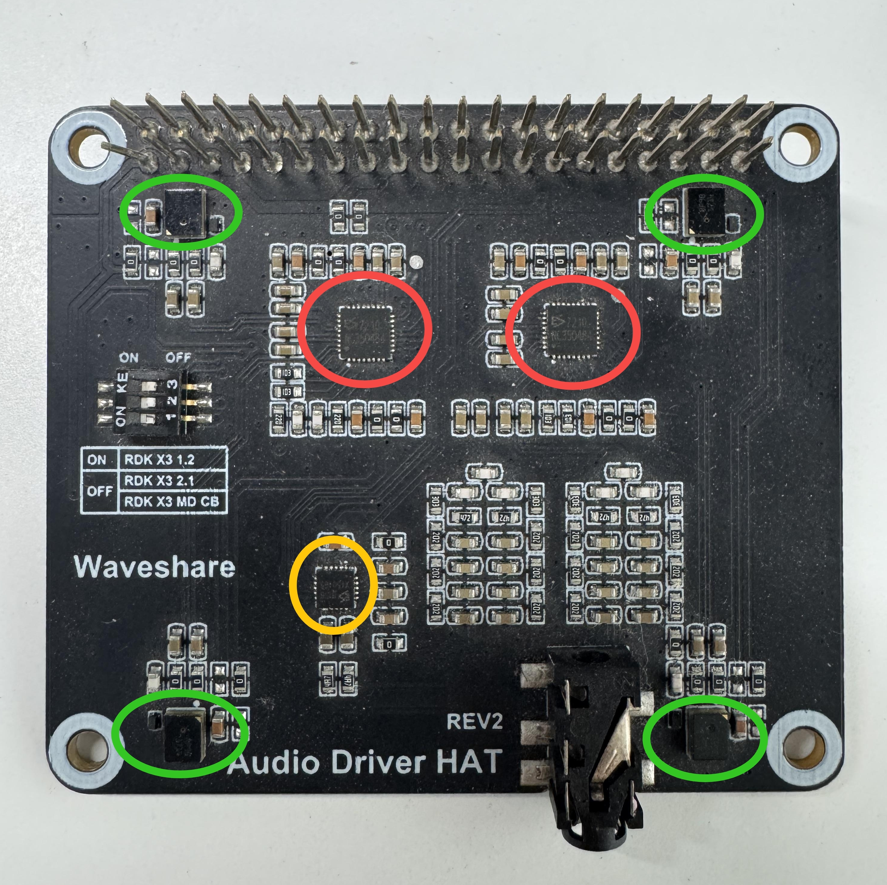
This section uses the Audio Driver HAT REV2 audio daughter board connected to the S100 development board as an example.
The audio daughter board contains two es7210 chips with I2C addresses 0x40/0x42. It can record 8-channel audio, with 4 channels receiving analog mic input and 2 channels for AEC echo cancellation of speaker data.
It contains one es8156 chip with I2C address 0x8. It can play 2-channel audio, outputting sound via headphones or speakers.
Refer to the physical diagram below: the red circles indicate the es7210, the yellow circle indicates the es8156, and the green circles indicate the 4 mics.
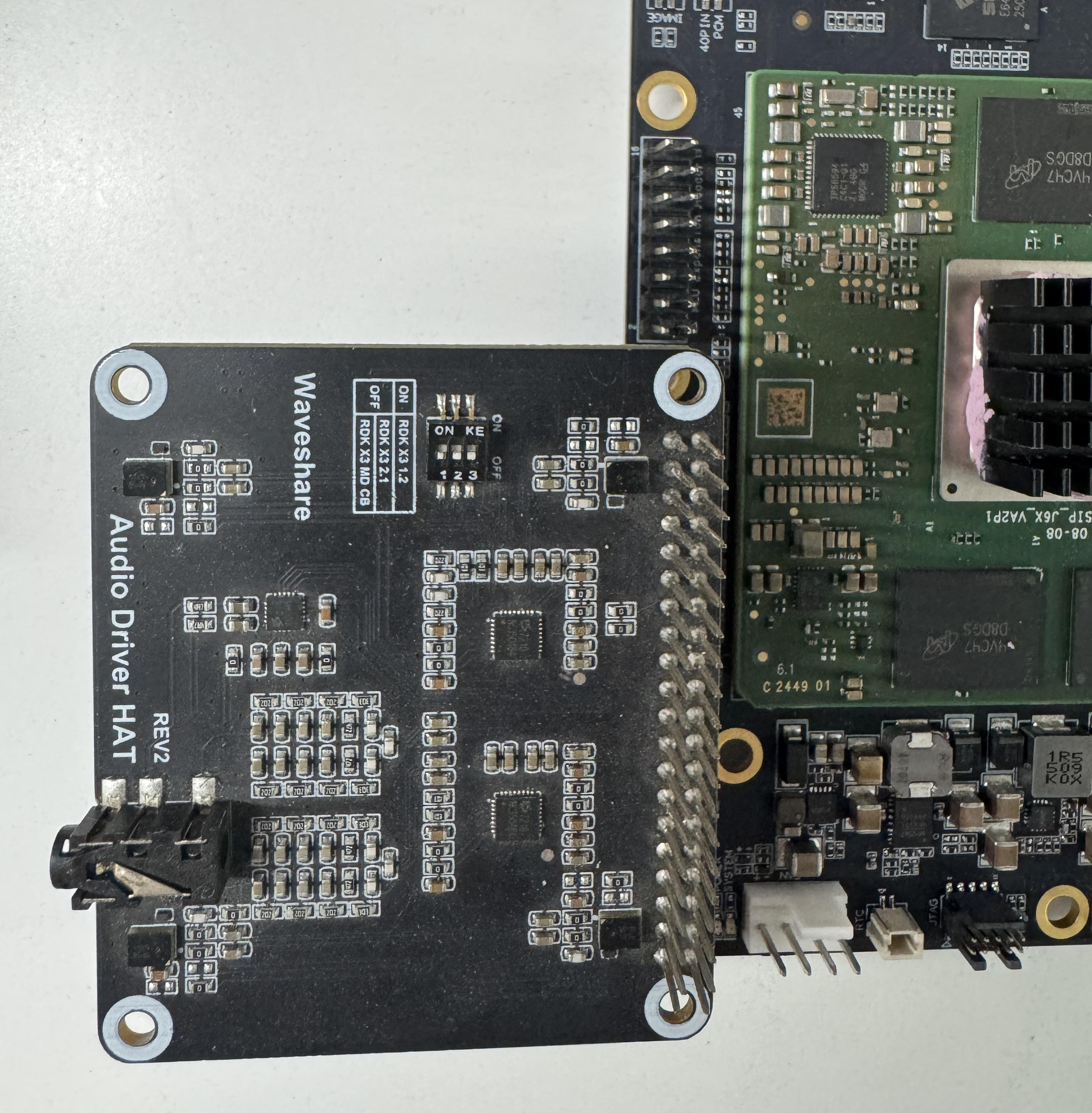
Connecting the Audio Daughter Board to the Development Board
The connection method is shown below:
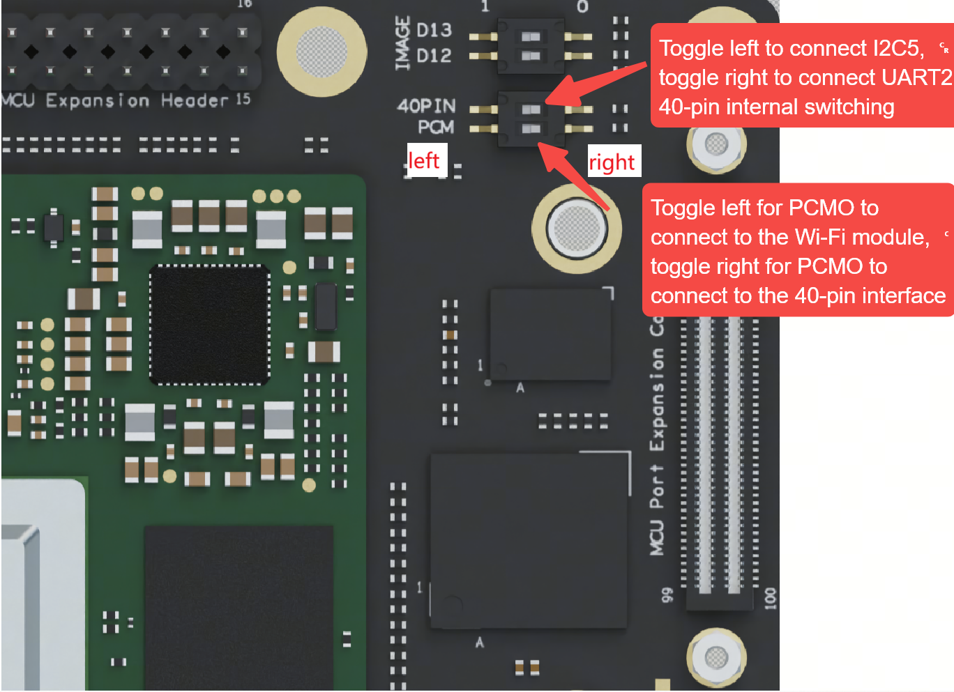
Note: The PCM pins on the 40-pin header are multiplexed with the PCIe Wi-Fi module. The hardware provides a DIP switch to switch the pin functionality.
When toggling the pin functions with the DIP switch, move the upper 40-pin DIP switch to the left, and move the lower PCM DIP switch to the right. As shown in the figure below: