3.3.2.3 Serial Port Application
The RDK S600 supports UART6 and UART7 on the self-locking 10-PIN interface, with an IO voltage of 3.3V.
Please refer to /app/40pin_samples/test_serial.py for details on how to use the serial port.
The pins mentioned below are for illustration only. Port values vary across different platforms, so the actual situation should prevail. You can also directly use the code in the /app/40pin_samples/ directory, which has been verified on the board.
Loopback Test
Connect TXD and RXD in hardware, then run the test program to perform write and read operations. The expected result is that the read data should exactly match the written data.
Hardware Connection
Before testing, short-circuit TXD and RXD:
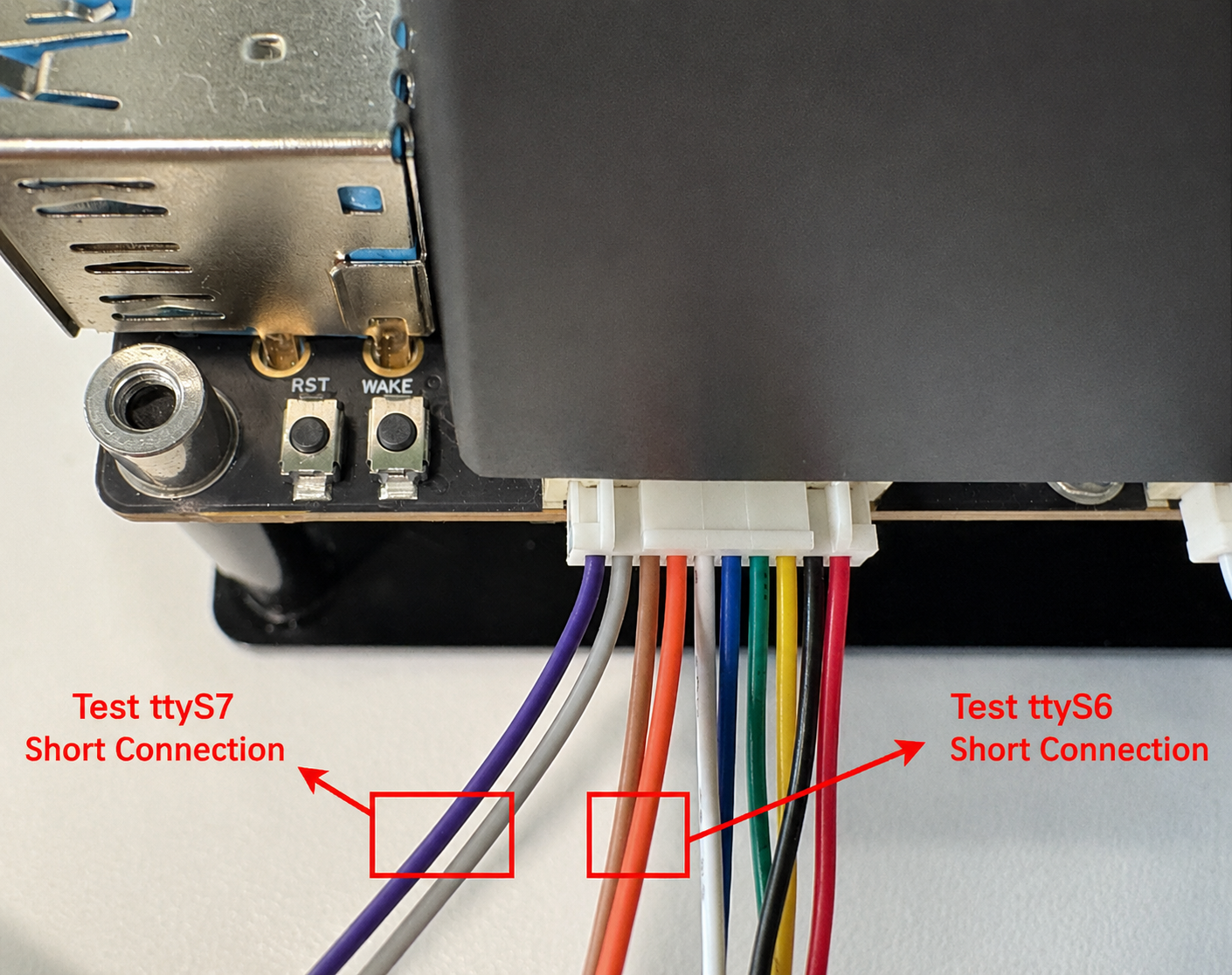
Test Process
- Run
python3 /app/40pin_samples/test_serial.py - From the printed serial devices (where /dev/ttyS0 is the system debug port, testing it is not recommended unless you fully understand its function), select the bus number and chip select number as input options. For example, RDK S600 selects
/dev/ttyS6or/dev/ttyS7.
Press Enter to confirm, and enter the baud rate parameter:
root@ubuntu:/app/40pin_samples# ./test_serial.py
List of enabled UART:
/dev/ttyS0  /dev/ttyS2  /dev/ttyS4  /dev/ttyS6
/dev/ttyS1  /dev/ttyS3  /dev/ttyS5  /dev/ttyS7

Please enter the serial device name to test:/dev/ttyS6
Please enter the baud rate (9600,19200,38400,57600,115200,921600):921600
Serial<id=0xfffe64a537f0, open=True>(port='/dev/ttyS6', baudrate=921600, bytesize=8, parity='N', stopbits=1, timeout=1, xonxoff=False, rtscts=False, dsrdtr=False)
- After the program runs correctly, it will continuously print
Send: AA55andRecv: AA55:
Starting demo now! Press CTRL+C to exit
Send:  AA55
Recv:  AA55
Test Code
The pin mapping between ttyS and uart hardware controllers in the device tree is as follows: ttyS0 uses uart2 pins, ttyS1 uses uart0 pins, ttyS2 uses uart1 pins. For example, when testing ttyS1, you should use pins 2 and 3 (uart0 TX/RX) of the J19 header. For specific pins, please refer to section Pin Definition and Application.
#!/usr/bin/env python3

import sys
import signal
import os
import time

# Import python serial library
import serial
import serial.tools.list_ports

def signal_handler(signal, frame):
    sys.exit(0)

def serialTest():
    print("List of enabled UART:")
    os.system('ls /dev/tty[a-zA-Z]*')
    uart_dev= input("Please enter the serial device name to test:")

    baudrate = input("Please enter the baud rate (9600,19200,38400,57600,115200,921600):")
    try:
        ser = serial.Serial(uart_dev, int(baudrate), timeout=1) # 1s timeout
    except Exception as e:
        print("open serial failed!\n")

    print(ser)

    print("Starting demo now! Press CTRL+C to exit")

    while True:
        test_data = "AA55"
        write_num = ser.write(test_data.encode('UTF-8'))
        print("Send: ", test_data)

        received_data = ser.read(write_num).decode('UTF-8')
        print("Recv: ", received_data)

        time.sleep(1)

    ser.close()
    return 0


if __name__ == '__main__':
    signal.signal(signal.SIGINT, signal_handler)
    if serialTest() != 0:
        print("Serial test failed!")
    else:
        print("Serial test success!")